Hitachi EX1200-7 Hydraulic Excavator Operational Technical Manual TOKAA90-EN-00 PDF
$29.95
Hitachi EX1200-7 Hydraulic Excavator Operational Technical Manual TOKAA90-EN-00 – PDF DOWNLOAD
Description
Hitachi EX1200-7 Hydraulic Excavator Operational Technical Manual TOKAA90-EN-00 – PDF DOWNLOAD
FILE DETAILS:
Hitachi EX1200-7 Hydraulic Excavator Operational Technical Manual TOKAA90-EN-00 – PDF DOWNLOAD
Language :English
Pages :413
Downloadable : Yes
File Type : PDF
IMAGES PREVIEW OF THE MANUAL:
DESCRIPRION:
Hitachi EX1200-7 Hydraulic Excavator Operational Technical Manual TOKAA90-EN-00 – PDF DOWNLOAD
INTRODUCTION
To The Reader
This manual is written for an experienced technician to provide PS information needed to maintain and repair this machine. The machine specification and description according to destination may be explained on this manual. Be sure to thoroughly read this manual for correct product information and service procedures.
Be sure to thoroughly read this manual for correct product information and service procedures.
If you have any questions or comments, at if you found any errors regarding the contents of this manual, please contact using “Service Manual Revision Request Form” at the end of this manual.
Manual Composition
- This manual consists the Technical Manual and the Workshop Manual.
- Information included in the Technical Manual: Technical information needed for redelivery and delivery, operation and activation of all devices and systems, operational performance tests, and troubleshooting procedures.
- Information included in the Workshop Manual: Technical information needed for maintenance and repair of the machine, tools and devices needed for maintenance and repair, maintenance standards, and removal / installation and assemble / disassemble procedures.
TABLE OF CONTENTS:
Hitachi EX1200-7 Hydraulic Excavator Operational Technical Manual TOKAA90-EN-00 – PDF DOWNLOAD
TOKAA90-EN-00 1
INTRODUCTION 3
SYMBOL AND ABBREVIATION 5
SECTION AND GROUP CONTENTS 7
SECTION 1 GENERAL 9
Group 1 Specifications 11
Specifications 11
Working Range (Backhoe) 12
Working Range (Be Backhoe) 13
Group 2 Component Layout 15
Main Component 15
Front Attachment 16
Electrical System (Overview) 17
Electrical System (In Cab) 18
Electrical System (Switch Panel) 19
Electrical System (Electrical Equipment Box) 20
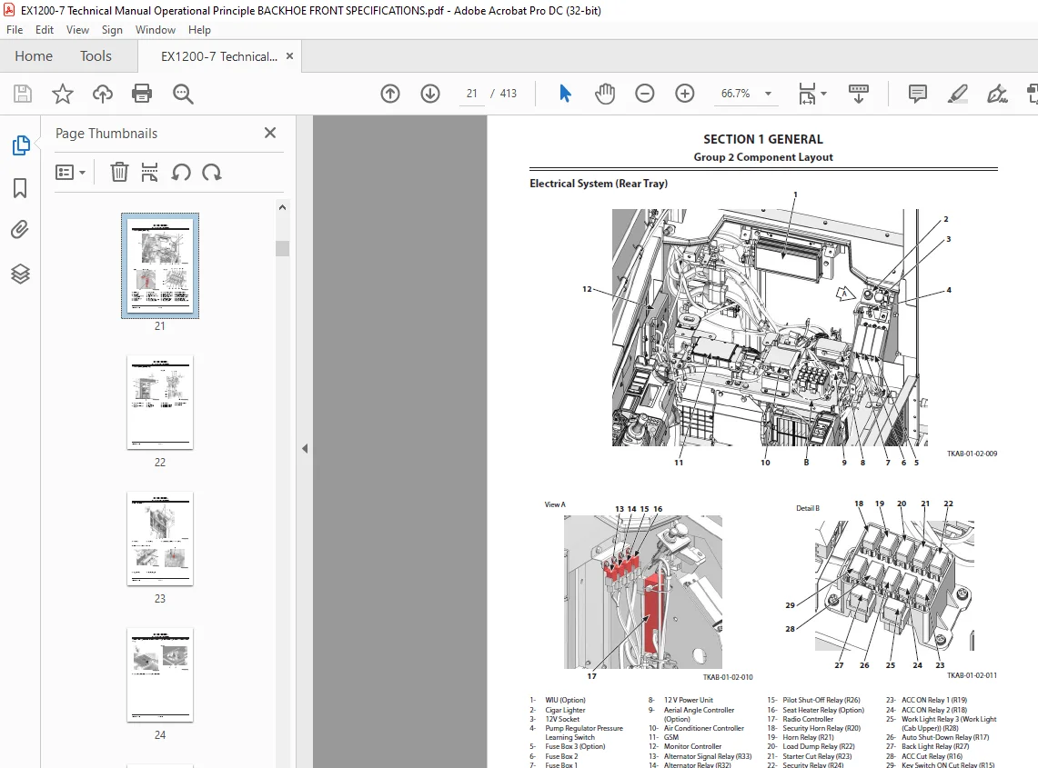
Electrical System (Rear Tray) 21
Electrical System (Battery Box) 22
Around Air Cleaner 23
Around Engine Compartment 23
Pressure Sensor (Main Control Valve 4-Spool Side)/Pressure Sensor (Main Control Valve 5-Spool Side) 24
Around Pump Device 25
Pump Device 26
Control Valve 27
Signal Control Valve 28
Solenoid Valve 29
Fan Valve (Oil Cooler, Radiator) 29
Engine 30
Around Oil Cooler 31
Around Radiator 31
Auto-Lubrication Device 32
Swing Device and Pressure Sensors for Front Attachment 33
Hydraulic Oil Tank 34
Fuel Tank 34
Sliding Fold-In Ladder 35
Group 3 Component Specifications 37
Engine 37
Engine Accessories 41
Hydraulic Component 42
Electrical Component 46
SECTION 2 SYSTEM 49
Group 1 Controller 51
Outline 51
DLU: Data Logging Unit 53
Group 2 Control System 55
Outline 55
Engine Control 60
Pump Control 80
Valve Control (Standard)106
Other Control124
Group 3 Engine System137
ECM System137
Group 4 Hydraulic System141
Outline141
Pilot Circuit142
Main Circuit152
Transmission Oil Cooling Circuit172
Fan Motor Circuit173
Group 5 Electrical System177
Outline177
Main Circuit178
Electric Power Circuit (Key Switch: OFF)180
Electric Power Circuit (Key Switch: ACC)182
Electric Power Circuit (Key Switch: ON)184
Starting Circuit (Key Switch: START)192
Charging Circuit (Key Switch: ON)194
Pilot Shut-Off Circuit (Key Switch: ON)196
Auto Shut-Down Circuit198
Engine Stop Circuit200
Surge Voltage Prevention Circuit202
Monitor Circuit205
Security Circuit206
Radio Circuit208
Air Conditioner Circuit208
Accessory Circuit211
Work Light Circuit212
Step Light Circuit214
Wiper/Washer Circuit216
Cab Light Circuit220
Sliding Fold-In Ladder Alarm Circuit222
Group 6 Air Conditioning System225
Outline225
Electrical Circuit Diagram228
Functions of Main Parts229
SECTION 3 COMPONENT OPERATION237
Group 1 Pump Device239
Outline239
Main Pump, Fan Pump240
Regulator for Main Pump242
Fan Pump Regulator250
Main Pump Control Solenoid Valve, Fan Pump Control Solenoid Valve266
Pilot Pump, Transmission Lubrication Pump268
Pump Delivery Pressure Sensor268
Regulator Pressure (Flow Rate Control Pressure) Sensor268
Group 2 Swing Device269
Outline269
Swing Reduction Gear270
Swing Motor271
Swing Parking Brake272
Valve Unit275
Group 3 Control Valve279
Outline279
Main Control Valve280
Swing Control Valve290
Hydraulic Circuit294
Flow Combiner Valve300
Main Relief Valve302
Overload Relief Valve (with Make-Up Function)306
Overload Relief Valve (Low Pressure)310
Regenerative Valve312
Flow Rate Control Valve318
Boom Lower Meter-In Cut Valve322
Anti-Drift Valve326
Bypass Shut-Out Valve330
Group 4 Pilot Valve333
Outline333
Operation (Front Attachment/Swing and Travel Pilot Valves)335
Operation (Bucket Open/Close Pilot Valve: only Loading Shovel)343
Shockless Function (Only for Travel Pilot Valve)350
Group 5 Travel Device351
Outline351
Travel Reduction Gear352
Travel Motor354
Parking Brake356
Travel Brake Valve358
Counterbalance Valve, Check Valve360
Overload Relief Valve364
Travel Motor Displacement Angle Control Valve368
Group 6 Signal Control Valve373
Outline373
Pilot Port374
Shuttle Valve379
Shockless Valve382
Flow Combiner Valve Control Spool, Swing Parking Brake Release Spool386
Group 7 Others (Upperstructure)387
Pilot Shut-Off Solenoid Valve387
Solenoid Valve389
Fan Motor391
Fan Valve392
Pilot Relief Valve396
Shockless Valve397
Accumulator399
Auto-Lubrication System400
Distribution Valve (Quicklub Lubrication System) (Standard)402
Distribution Valve (Centro Matic Lubrication System) (Option)405
Group 8 Others (Undercarriage)407
Swing Bearing407
Center Joint408
Track Adjuster409
SERVICE MANUAL REVISION REQUEST FORM413
S.M 30/1/25