Hitachi Ex150LC-5 160LC-5 Operational Principle+Troubleshooting+Workshop Manual – PDF DOWNLOAD
Original price was: $54.95.$25.95Current price is: $25.95.
Hitachi Ex150LC-5 160LC-5 Operational Principle+Troubleshooting+Workshop Manual
This Listing includes all of the manuals mentioned below:
- Hitachi Ex150LC-5 160LC-5 Excavator (Operational Principle,Troubleshooting)Technical Manual
- Hitachi Ex150LC-5 160LC-5 Excavator Workshop Manual
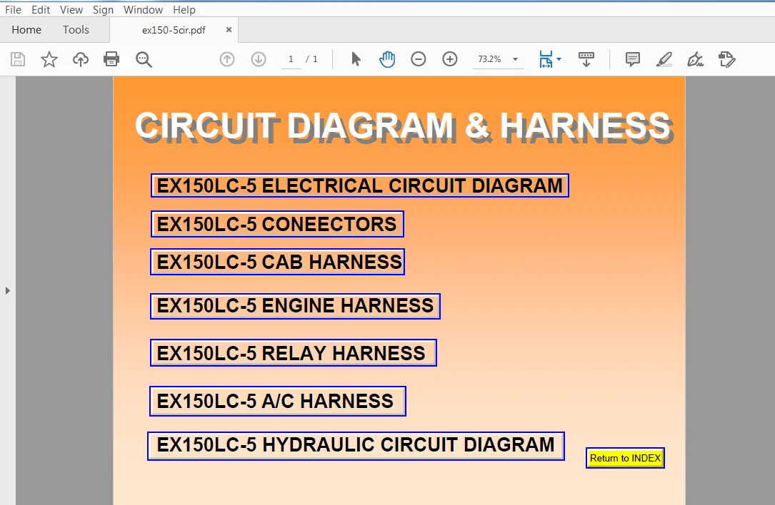
- Hitachi Ex150LC-5 160LC-5 Excavator Circuit Diagram & Harness
Description
Hitachi Ex150LC-5 160LC-5 Operational Principle+Troubleshooting+Workshop Manual
FILE DETAILS:
Hitachi Ex150LC-5 160LC-5 Operational Principle+Troubleshooting+Workshop Manual
This Listing includes all of the manuals mentioned below:
- Hitachi Ex150LC-5 160LC-5 Excavator (Operational Principle,Troubleshooting)Technical Manual
- Hitachi Ex150LC-5 160LC-5 Excavator Workshop Manual
- Hitachi Ex150LC-5 160LC-5 Excavator Circuit Diagram & Harness
DESCRIPTION:
Hitachi Ex150LC-5 160LC-5 Operational Principle+Troubleshooting+Workshop Manual
INTRODUCTION:
TO THE READER:
• This manual is written for an experienced technician to provide technical information needed to maintain and repair this machine.
• Be sure to thoroughly read this manual for correct product information and service procedures.
• If you have any questions or comments, at if you found any errors regarding the contents of this manual, please contact using “Service Manual Revision Request Form” at the end of this manual.
ADDITIONAL REFERENCES:
• Please refer to the materials listed below in addition to this manual.
• The Operator’s Manual
• The Parts Catalog
• The Engine Manual
• Parts Catalog of the Engine
• Hitachi Training Material
MANUAL COMPOSITION:
• This manual consists of three portions: the Technical Manual (Operational Principle), the Technical Manual (Troubleshooting) and the Workshop Manual.
• Information included in the Technical Manual (Operational Principle): technical information needed for redelivery and delivery, operation and activation of all devices and systems.
• Information included in the Technical Manual (Troubleshooting): technical information needed for operational performance tests, and troubleshooting procedures.
• Information included in the Workshop Manual: technical information needed for maintenance and repair of the machine, tools and devices needed for maintenance and repair, maintenance standards, and removal/installation and assemble/ disassemble procedures.
TABLE OF CONTENTS:
Hitachi Ex150LC-5 160LC-5 Operational Principle+Troubleshooting+Workshop Manual
SECTION 1
GENERAL
Group 1 Specification
Specifications T1-1-1
Working Ranges and Machine
Dimensions for Transportation T1-1-2
Component Specification T1-1-3
Group 2 Component Layout
Main Components T1-2-1
Electrical System (Overall System) T1-2-2
Electrical System (Relays) T1-2-3
Electrical System
(Monitor and Switch Panels) T1-2-4
Pump and Related Parts T1-2-5
Other Components T1-2-6
SECTION 1 Control System
Outline T2-1-1
Engine Control T2-1-2
Pump Control T2-18
Valve Control T2-1-1D
Other Control Function T2-1-13
SECTION 2 Hydraulic System
Main Circuit T2-2-1
Pflot Circwt T2-2-2
Neutral Circu1t T2-2-3
Single Actuator Operation– T2-2-3
Combined Operation T2-2—4
SECTION 3 Electrical System
Outline T2-31
Electric Power Circuit T2-3—2
Bulb Check Circu1t T2—3—3
Preheat Circh T2434
Starting Circmt T2-3—6
Charging Circurt T2-3-8
Surge Voltage Prevention Circuit T2-3-11
Accessory Circu1t T2-3-12
Engine Stop CichIt T2-3-13
SECTION 3
COMPONENT OPERATION
Group 1 Pump Device
Outline T3-1-1
Main Pump T3-1-2
Regulator T3-1-5
Pilot Pump T3-1-13
N Sensor (Engine Speed Sensor) T3-1-13
Pump Delivery Pressure Sensor T3-1-13
Group 2 Swing Device
Outline T3-2-1
Swing Motor T3-2-2
Valve Unit T3-2-4
Swing Parking Brake T3-2-6
Swing Reduction Gear T3-2-7
Group 3 Control Valve
Outline T3-3-1
Hydraulic Circuit T3-3-6
Flow Combiner Valve T3-3-8
Pump Control Valve T3-3-9
Main Relief ValveT3-3-11
Overload Relief Valve
(With Make-Up Function)T3-3-11
Arm Regenerative Valve T3-3-12
Boom Anti-Drift Valve,
Arm Anti-Drift Valve T3-3-14
Bucket Flow Control Valve T3-3-14
Travel Flow Control Valve T3-3-16
Travel / Boom Lower
Selector Valve T3-3-16
Boom Regenerative Valve T3-3-18
Group 4 Pilot Valve
Outline T3-4-1
Operation T3-4-2
Group 5 Travel Device
Outline T3-5-1
Travel Reduction Gear T3-5-2
Travel Motor T3-5-3
Travel Brake Valve T3-5-8
Parking Brake T3-5-10
Group 6 Others (Upperstructure)
Pilot Shut-Off Valve T3-6-1
Shockless Valve T3-6-2
Solenoid Valve Unit T3-6-4
Pilot Relief Valve T3-6-6
EC Motor T3-6-6
Group 7 Others (Undercarriage)
Swing Bearing T3-7-1
Center Joint T3-7-2
Track Adjuster T3-7-3
SECTION 4
OPERATIONAL
PERFORMANCE TEST
Group 1 Introduction
Operational Performance Tests T4-1-1
Preparation for Performance Tests T4-1-2
Group 2 Engine Test
Engine Speed T4-2-1
Engine Compression Pressure T4-2-3
Valve Clearance Adjustment T4-2-4
Nozzle Check T4-2-6
Injection Timing T4-2-8
Group 3 Excavator Test
Travel Speed T4-3-1
Track Revolution Speed T4-3-2
Mistrack Check T4-3-3
Travel Parking Function Check T4-3-4
Swing Speed T4-3-5
Swing Function Drift Check T4-3-6
Swing Motor Leakage T4-3-7
Swing Bearing Play T4-3-8
Maximum Swingable Slant Angle T4-3-9
Hydraulic Cylinder Cycle Time T4-3-10
Dig Function Drift CheckT4-3-11
Control Lever Operating Force T4-3-12
Control Lever Stroke T4-3-13
Combined Boom Raise/Swing
Function Check T4-3-14
Group 4 Component Test
Primary Pilot Pressure T4-4-1
Secondary Pilot Pressure T4-4-3
Solenoid Valve Set Pressure T4-4-4
Main Pump Delivery Pressure T4-4-6
Main Relief Valve Set Pressure T4-4-7
Overload Relief Valve Set Pressure T4-4-11
Main Pump Flow Test T4-4-14
Swing Motor Drainage T4-4-18
Travel Motor Drainage T4-4-20
Group 5 Standard
Operational Performance Standard
Table T4-5-1
Main Pump P-Q Diagram T4-5-4
Injection Pump T4-5-5
Group 1 Diagnosing Procedure
Introduction T51-1
Diagnosing Procedure T5-1-2
DrEX Start-Up Procedure T5-1-4
DrEX Fault Code T5-1-5
DrEX Monitoring Function T5-1-6
DrEX Special Function (Service Mode) T5-1-7
Adjustable Data List T5—1-14
Group 2 Component Layout
Main Components- T52-1
Electrical System (Overall System) TS-2-2
Electrical System (Relays) T5—2-3
Electrical System
(Monitor and Switch Panels) T5-2-4
Pump and Related Parts T5—2-5
Control Valve T52-6
Others Components TS-2-1O
Group 3 Troubleshooting A
Troubleshooting A Procedure- T5-31
Fault Code T532
Fault Code 01 T5-3-4
Fault Code 02, 03 T5-3-5
Fault Code 04, 05 T5345
Fault Code 06 T5-3-7
Fault Code 07 T53-8
Sensor Operating Range List T5-3-9
Group 4 Troubleshooting B
Troubleshooting 8 ProcedureT541
Relationship Mtween Machine Trouble
Symptoms and Parts in TroubleT542
Correlation between Trouble
Symptoms and Part FailuresT5-4-12
Engine Troubleshooting T5418
Actuator Control System
Troubleshooting T5432
Front Attachment Control System
Troubleshooting T5438
Swing System Troubleshooting T5-4-50
‘lTavel System Troubleshooting T5~4-53
Troubleshooting for Other Functions T5-4-58
Engine Speed Adjustment and
Engine Leamlng T5460
Exchange Inspection Method T5461
Group 5 Troubleshooting C
Troubleshooting C Procedure T5-51
Malfunction of Coolant
Temperature Gauge T5-5-2
Malfunction of Fuel Gauge T5-5c4
Malfunction of Indicator Light
Check System T55-6
Malfunction of Level Check Switch T55-6
Malfunction of Engine Oil Level
Indicator T558
Malfunction of Coolant Level
Indicator T5-5—1D
Malfunction of Hydraulic Oil Level
Indicator T5-5-12
Malfunction of Alternator Indicator T5-514
Malfunction of Engine Oil Pressure
Indicator T5-5-16
Malfunction of Overheat Indicator T5-518
Malfunction of Fuel Level Indicator T5-5-20
Malfunction of Air Filter Restriction
Indicator T5-5-22
Malfunction of Buzzer T5524
Malfunction of Hour Meter T5-5-26
Group 6 Electrical System Inspection
Precautions for Inspection and
Maintenance— T5-6—1
Instructions for Disconnecting
Connectors T5-6-3
Fuse Continuity Test T5-6-4
Inspection and Replacement of
Fusible Links T5-6-5
Battery Voltage Check T5-6—6
How to Troubleshoot Alternator
Malfunctions T5-6-7
Continuity Check T5-6—8
Voltage and Current Check T5—6-10
Replacement of Relay T5-6-14
Group 7 Harness Check
Circuit Check T57-1
HITACHI EX150LC-5 160LC-5 OPERATIONAL PRINCIPLE+TROUBLESHOOTING+WORKSHOP MANUAL – PDF DOWNLOAD:
IMAGES PREVIEW OF THE MANUAL:
PLEASE NOTE:
- This is the SAME exact manual used by your dealers to fix your vehicle.
- The same can be yours in the next 2-3 mins as you will be directed to the download page immediately after paying for the manual.
- Any queries / doubts regarding your purchase, please feel free to contact [email protected]