Hitachi EX200-5 200LC-5 220-5 220LC-5 230LC-5 270-5 270LC-5 Excavator Operational Principle+Troubleshooting+Workshop Manual – PDF DOWNLOAD
Original price was: $54.95.$24.95Current price is: $24.95.
Hitachi EX200-5 200LC-5 220-5 220LC-5 230LC-5 270-5 270LC-5 Excavator Operational Principle+Troubleshooting+Workshop Manual
This Listing includes all of the manuals mentioned below:
- Hitachi EX200-5 200LC-5 220-5 220LC-5 230LC-5 270-5 270LC-5 Excavator (Operational Principle,Troubleshooting) Manual
- Hitachi EX200-5 200LC-5 220-5 220LC-5 230LC-5 270-5 270LC-5 Excavator Workshop Manual
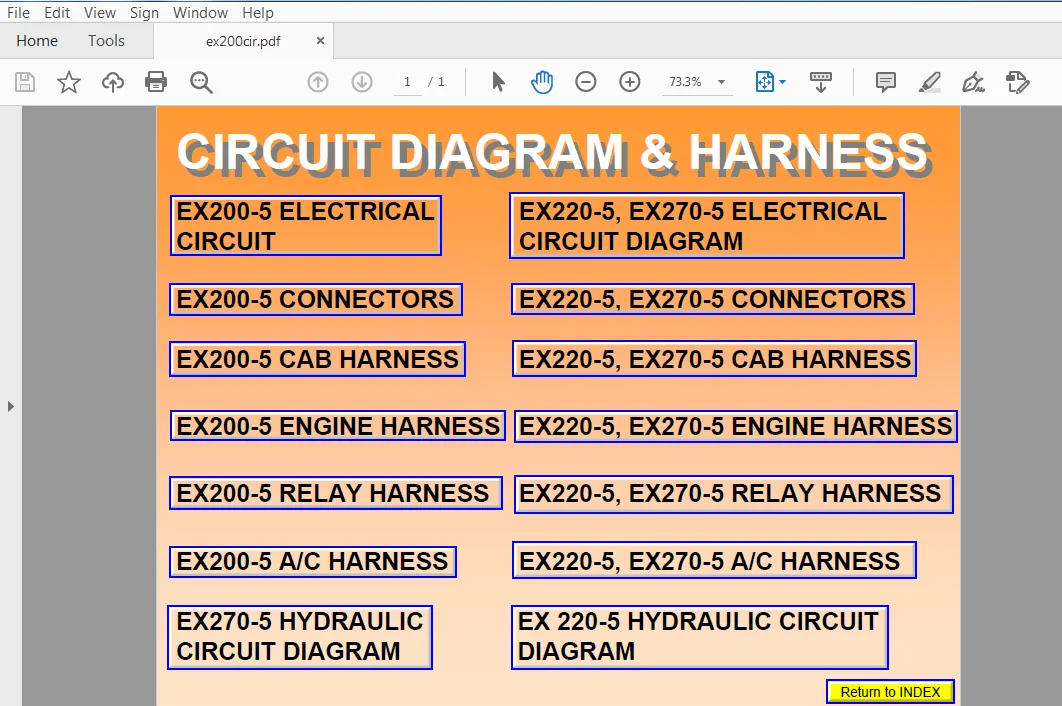
- Hitachi EX200-5 200LC-5 220-5 220LC-5 230LC-5 270-5 270LC-5 Excavator Circuit Diagram & Harness
Description
Hitachi EX200-5 200LC-5 220-5 220LC-5 230LC-5 270-5 270LC-5 Excavator Operational Principle+Troubleshooting+Workshop Manual
FILE DETAILS:
Hitachi EX200-5 200LC-5 220-5 220LC-5 230LC-5 270-5 270LC-5 Excavator Operational Principle+Troubleshooting+Workshop Manual
This Listing includes all of the manuals mentioned below:
- Hitachi EX200-5 200LC-5 220-5 220LC-5 230LC-5 270-5 270LC-5 Excavator (Operational Principle,Troubleshooting) Manual
- Hitachi EX200-5 200LC-5 220-5 220LC-5 230LC-5 270-5 270LC-5 Excavator Workshop Manual
- Hitachi EX200-5 200LC-5 220-5 220LC-5 230LC-5 270-5 270LC-5 Excavator Circuit Diagram & Harness
DESCRIPTION:
Hitachi EX200-5 200LC-5 220-5 220LC-5 230LC-5 270-5 270LC-5 Excavator Operational Principle+Troubleshooting+Workshop Manual
INTRODUCTION:
TO THE READER:
• This manual is written for an experienced technician to provide technical information needed to maintain and repair this machine.
• Be sure to thoroughly read this manual for correct product information and service procedures.
• If you have any questions or comments, at if you found any errors regarding the contents of this manual, please contact using “Service Manual Revision Request Form” at the end of this manual.
ADDITIONAL REFERENCES:
• Please refer to the materials listed below in addition to this manual.
• The Operator’s Manual
• The Parts Catalog
• The Engine Manual
• Parts Catalog of the Engine
• Hitachi Training Material
MANUAL COMPOSITION:
• This manual consists of three portions: the Technical Manual (Operational Principle), the Technical Manual (Troubleshooting) and the Workshop Manual.
• Information included in the Technical Manual (Operational Principle): technical information needed for redelivery and delivery, operation and activation of all devices and systems.
• Information included in the Technical Manual (Troubleshooting): technical information needed for operational performance tests, and troubleshooting procedures.
• Information included in the Workshop Manual: technical information needed for maintenance and repair of the machine, tools and devices needed for maintenance and repair, maintenance standards, and removal/installation and assemble/ disassemble procedures.
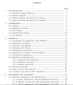
TABLE OF CONTENTS:
Hitachi EX200-5 200LC-5 220-5 220LC-5 230LC-5 270-5 270LC-5 Excavator Operational Principle+Troubleshooting+Workshop Manual
- Hitachi EX200-5 200LC-5 220-5 220LC-5 230LC-5 270-5 270LC-5 Excavator Workshop Manual
SECTION 1
GENERAL INFORMATION
Group 1 Precautions for Disassembling
and Assembling
Precautions for Disassembling and
AssemblingW1-1-1
Group 2 Tightening Torque
Tightening Torque Specification W1-2-1
Torque ChartW1-2-2
Piping JointW1-2-5
SECTION 2
UPPERSTRUCTURE
—CONTENTS—
Group 1 Cab
Remove and Install CabW2-1-1
Dimensions of the Cab Glass W2-1-7
Group 2 Counterweight
Remove and Install
Counterweight W2-2-1
Group 3 Main Frame
Remove and Install
Main Frame W2-3-1
Group 4 Pump Device
Remove and Install
Pump Device W2-4-1
Disassemble Pump Device W2-4-4
Assemble Pump DeviceW2-4-12
Disassemble RegulatorW2-4-26
Assemble Regulator W2-4-28
Disassemble and Assemble
Pilot PumpW2-4-30
Maintenance StandardW2-4-32
Group 5 Control Valve
Remove and Install
Control Valve W2-5-1
Disassemble
Control Valve 1 W2-5-4
Assemble
Control Valve 1 W2-5-6
Disassemble
Control Valve 2 W2-5-10
Assemble
Control Valve 2-1 W2-5-14
Assemble
Control Valve 2-2 W2-5-16
Disassemble
Control Valve 3 W2-5-20
Assemble
Control Valve 3 W2-5-22
Disassemble Control Valve 4 W2-5-26
Assemble Control Valve 4-1 W2-5-30
Assemble Control Valve 4-2 W2-5-34
Group 6 Swing Device
Remove and Install
Swing DeviceW2-6-1
Disassemble Swing DeviceW2-6-4
Assemble Swing DeviceW2-6-10
Disassemble Swing MotorW2-6-14
Assemble Swing Motor W2-6-18
Maintenance StandardW2-6-22
Disassemble Valve Unit W2-6-24
Assemble Valve Unit W2-6-2
SECTION 3
UNDERCARRIAGE
—CONTENTS—
Group 1 Swing Bearing
Remove and Install
Swing Bearing W3-1-1
Disassemble Swing Bearing W3-1-3
Assemble Swing Bearing W3-1-5
Group 2 Travel Device
Remove and Install
Travel Device W3-2-1
Disassemble Travel Device W3-2-4
Assemble Travel Device W3-2-8
Disassemble Travel Motor W3-2-14
Assemble Travel Motor W3-2-18
Disassemble and Assemble
Brake Valve W3-2-24
Maintenance Standard W3-2-30
Group 3 Center Joint
Remove and Install Center Joint W3-3-1
Disassemble Center Joint W3-3-4
Assemble Center JointW3-3-6
Maintenance StandardW3-3-9
Group 4 Track Adjuster
Remove and Install
Track Adjuster W3-4-1
Disassemble Track Adjuster W3-4-2
Assemble Track AdjusterW3-4-10
Group 5 Front Idler
Remove and Install Front Idler W3-5-1
Disassemble Front Idler W3-5-2
Assemble Front IdlerW3-5-6
Maintenance StandardW3-5-8
Group 6 Upper and Lower Roller
Remove and Install
Upper Roller W3-6-1
Remove and Install
Lower Roller W3-6-4
Disassemble Lower Roller W3-6-8
Assemble Lower Roller W3-6-10
Maintenance StandardW3-6-12
Group 7- Track
Remove and Install Track W3-7-1
Maintenance StandardW3-7-7
SECTION 4
FRONT ATTACHMENT
—CONTENTS—
Group 1 Front Attachment
Remove and Install
Front Attachment W4-1-1
Maintenance StandardW4-1-8
Standard Dimensions for Arm and Bucket
Connection W4-1-11
Group 2 Cylinder
Removeand Install Cylinder W4-2-1
Hydraulic Circuit Pressure Release
ProcedureW4-2-11
Disassemble Cylinder W4-2-12
Assemble CylinderW4-2-16
Maintenance StandardW4-2-20
SECTION 5
ENGINE AND ACCESSORY
CONTENTS
General Introduction
General Repair Instructions 1-2
Notes on the Format of
This Manual1-2
Main Data and Specifications1-6
Performance Curve 1-9
External View1-15
Tightening Torque Specifications 1-21
Angular Nut and Bolt Tightening
Method 1-23
Major Parts Fixing Nuts and Bolts 1-25
Identifications 1-36
Maintenance
Lubricating System 2-2
Fuel System 2-2
Cooling System 2-6
Valve Clearance Adjustment 2-6
Injection Timing 2-8
Compression Pressure
Measurement 2-12
Turbocharger Inspection 2-13
Engine Repair Kit2-14
Recommended Lubricants 2-16
Engine Oil Viscosity Chart 2-16
Engine Assembly 1 (Disassembly)
External Parts Disassembly Steps 3-2
Major Components 3-8
Rocker Arm and Rocker Arm Shaft
Disassembly Steps 3-13
Cylinder Head Disassembly Steps 3-14
Piston and Connecting Rod
Disassembly Steps 3-15
Engine Assembly 2
(inspection and Repair)
Cylinder Head 4-2
Valve Guide 4-3
Valve Spring 4-6
Tappet 4-7
Push Rod 4-8
Rocker Arm Shaft and Rocker Arm 4-8
Idler Gear and Idler Gear Shaft 4-9
Camshaft 4-10
Cylinder Body and Liner 4-11
Piston and Piston Ring4-16
Piston Pin 4-18
Connecting Rod 4-19
Crankshaft 4-21
Flywheel and Flywheel Housing 4-28
Timing Gear Case Cover 4-29
Engine Assembly 3 (Reassembly)
Piston and Connecting Rod
Reassembly Steps 5-2
Cylinder Head Reassembly Steps 5-4
Rocker Arm and Rocker Shaft
Reassembly Steps 5-8
Major Component Reassembly Steps 1 5-9
Major Component Reassembly Steps 2 5-14
External Parts Reassembly Steps
(Left-Hand Side) 5-18
External Parts Reassembly Steps
(Right-Hand Side) 5-22
Engine Tuning Operation 5-25
Engine Sectional View 5-27
155W-5-2
Lubricating System
General Description 6-2
Oil Pump 6-3
Oil Cooler 6-5
Cooling System
General Description 7-2
Water Pump 7-3
Thermostat 7-8
Fuel System
General Description 8-2
Injection Nozzle 8-3
Injection Pump Calibration Data8-8
Turbocharger
General Description 9-2
Turbocharger Identification 9-3
Inspection and Repair9-4
Air Compressor
General Description 10-2
Disassembly Steps 10-3
Inspection and Repairs 10-4
Reassembly Steps10-6
Engine Electricals
Starter Motor Identification11-2
Starter Main Data and Specifications 11-3
Starter Motor Sectional View11-4
Starter Motor Exploded View 11-5
Alternator Identification 11-6
Main Data and Specifications11-7
Alternator Sectional View11-8
Alternator Exploded View11-9
Troubleshooting
Hard Starting 12-2
1) Starter Inoperative 12-2
2) Starter Operates but
Engine Does not Turn Over 12-3
3) Engine Turns Over but Does not Starts
Though Fuel is Bearing Delivered to the
Injection Pump12-4
4) Engine Turns Over but Does not Start 12-5
Unstable Low Idling 12-6
Insufficient Power 12-9
Excessive Fuel Consumption 12-12
Excessive Oil Consumption 12-14
Overheating 12-15
Whity Exhaust Smoke12-17
Darkish Exhaust Smoke12-18
Oil Pressure does not Rise 12-19
Abnormal Engine Noise 12-21
Special Tool List
Special Tool List13-2
Conversion Table
Length 14-1
Area14-3
Volume 14-3
Mass14-5
Pressure 14-6
Torque 14-7
Temperature 14-8
- Hitachi EX200-5 200LC-5 220-5 220LC-5 230LC-5 270-5 270LC-5 Excavator (Operational Principle,Troubleshooting) Manual
SECTION 1
GENERAL
Group 1 Specification
Specifications T1-1-1
Working Ranges and Machine Dimensions for
Transportation T1-1-2
Component Specification T1-1-3
Group 2 Component Layout
Main Components T1-2-1
Electrical System (Overall System) T1-2-2
Electrical System (Relays) T1-2-3
Electrical System
(Monitor and Switch Panels) T1-2-4
Pump and Related Parts T1-2-5
Other Components T1-2-6
SECTION 2
SYSTEM
Group 1 Control System
Outline T2-1-1
Engine Control T2-1-2
Valve Control T2-1-8
Other Control Function T2-1-11
Group 2 Hydraulic System
Main Circuit T2-2-1
Pilot Circuit T2-2-2
Neutral Circuit T2-2-3
Single Actuator Operation T2-2-3
Combined Operation T2-2-4
Group 3 Electrical System
Outline T2-3-1
Electric Power Circuit T2-3-2
Bulb Check Circuit T2-3-3
Preheat Circuit T2-3-4
Starting Circuit T2-3-6
Charging Circuit T2-3-8
Surge Voltage Prevention Circuit T2-3-11
Accessory Circuit T2-3-12
Engine Stop Circuit T2-3-13
SECTION 3
COMPONENT OPERATION
Group 1 Pump Device
Outline T3-1-1
Main Pump T3-1-2
Regulator T3-1-5
Pilot Pump T3-1-12
Pump Delivery Pressure Sensor T3-1-12
Group 2 Swing Device
Outline T3-2-1
Swing Motor T3-2-2
Brake Valve T3-2-4
Swing Parking Brake T3-2-6
Swing Reduction Gear T3-2-7
Group 3 Control Valve
Outline T3-3-1
Hydraulic Circuit T3-3-6
Flow Combiner Valve T3-3-8
Pump Control Valve T3-3-9
Main Relief ValveT3-3-11
Overload Relief Valve
(With Make-Up Function)T3-3-11
Arm Regenerative Valve T3-3-12
Boom Anti-Drift Valve,
Arm Anti-Drift Valve T3-3-14
Bucket Flow Control Valve T3-3-14
Travel Flow Control Valve T3-3-16
Travel / Boom Lower
Selector Valve T3-3-16
Boom Regenerative Valve T3-3-18
Group 4 Pilot Valve
Outline T3-4-1
Operation T3-4-2
Group 5 Travel Device
Outline T3-5-1
Travel Reduction Gear T3-5-2
Travel Motor T3-5-3
Travel Brake Valve T3-5-10
Parking Brake T3-5-14
Group 6 Others (Upperstructure)
Pilot Shut-Off Valve T3-6-1
Shockless Valve T3-6-2
Solenoid Valve Unit T3-6-4
Pilot Relief Valve T3-6-6
EC Motor T3-6-6
Group 7 Others (Undercarriage)
Swing Bearing T3-7-1
Center Joint T3-7-2
Track Adjuster T3-7-3
SECTION 4
OPERATIONAL
PERFORMANCE TEST
Group 1 Introduction
Operational Performance Tests T4-1-1
Preparation for Performance Tests T4-1-2
Group 2 Engine Test
Engine Speed T4-2-1
Engine Compression Pressure T4-2-3
Valve Clearance Adjustment T4-2-4
Injection Timing T4-2-8
Group 3 Excavator Test
Nozzle Check T4-2-6
Travel Speed T4-3-1
Track Revolution Speed T4-3-2
Mistrack Check T4-3-3
Travel Parking Function Check T4-3-4
Swing Speed T4-3-5
Swing Function Drift Check T4-3-6
Swing Motor Leakage T4-3-7
Swing Bearing Play T4-3-8
Maximum Swingable Slant Angle T4-3-9
Hydraulic Cylinder Cycle Time T4-3-10
Dig Function Drift CheckT4-3-11
Control Lever Operating Force T4-3-12
Control Lever Stroke T4-3-13
Combined Boom Raise/Swing
Function Check T4-3-14
Group 4 Component Test
Primary Pilot Pressure T4-4-1
Secondary Pilot Pressure T4-4-3
Solenoid Valve Set Pressure T4-4-4
Main Pump Delivery Pressure T4-4-6
Main Relief Valve Set Pressure T4-4-7
Overload Relief Valve Set Pressure T4-4-11
Main Pump Flow Test T4-4-14
Swing Motor Drainage T4-4-20
Travel Motor Drainage T4-4-22
Group 5 Standard
Operational Performance Standard
Table T4-5-1
Main Pump P-Q Diagram T4-5-4
Injection Pump T4-5-6
SECTION 5
TROUBLESHOOTING
Group 1 Diagnosing Procedure
Introduction T5-1-1
Diagnosing Procedure T5-1-2
DrEX T5-1-4
DrEX Start-Up Procedure T5-1-4
DrEX Fault Code T5-1-5
DrEX Monitoring Function T5-1-6
DrEX Special Function (Service Mode) T5-1-7
Adjustable Data List T5-1-14
Group 2 Component Layout
Main Components T5-2-1
Electrical System (Overall System) T5-2-2
Electrical System (Relays) T5-2-3
Electrical System
(Monitor and Switch Panels) T5-2-4
Pump and Related Parts T5-2-5
Control Valve T5-2-6
Others Components T5-2-10
Group 3 Troubleshooting A
Troubleshooting A Procedure T5-3-1
List of Fault Code T5-3-2
Fault Code 01 T5-3-4
Fault Code 02, 03 T5-3-5
Fault Code 04, 05 T5-3-6
Fault Code 06 T5-3-7
Fault Code 07 T5-3-8
Sensor Operating Range List T5-3-9
Group 4 Troubleshooting B
Troubleshooting B Procedure T5-4-1
Relationship between Machine Trouble
Symptoms and Parts in Trouble T5-4-2
Correlation between Trouble
Symptoms and Part Failures T5-4-10
Engine Troubleshooting T5-4-16
Actuator Control System
Troubleshooting T5-4-28
Front Attachment Control System
Troubleshooting T5-4-34
Swing System Troubleshooting T5-4-46
Travel System Troubleshooting T5-4-49
Troubleshooting for Other Functions T5-4-54
Engine Speed Adjustment and
Engine Learning T5-4-56
Exchange Inspection Method T5-4-57
Emergency Boom Lowering Procedure T5-4-58
HITACHI EX200-5 200LC-5 220-5 220LC-5 230LC-5 270-5 270LC-5 EXCAVATOR OPERATIONAL PRINCIPLE+TROUBLESHOOTING+WORKSHOP MANUAL – PDF DOWNLOAD:
IMAGES PREVIEW OF THE MANUAL:
PLEASE NOTE:
- This is the SAME MANUAL used by the dealerships to diagnose your vehicle
- No waiting for couriers / posts as this is a PDF manual and you can download it within 2 minutes time once you make the payment.
- Your payment is all safe and the delivery of the manual is INSTANT – You will be taken to the DOWNLOAD PAGE.
- So have no hesitations whatsoever and write to us about any queries you may have : heydownloadss @gmail.com