Hitachi EX215 Excavator Operational Principle+Troubleshooting+Workshop Manual – Hitachi EX215 – PDF Download
Original price was: $84.95.$25.95Current price is: $25.95.
Hitachi EX215 Excavator Operational Principle+Troubleshooting+Workshop Manual – Hitachi EX215
This Listing includes all of the manuals mentioned below:
- Hitachi Ex135-EX215 Excavator Engine Technical Workshop Manual
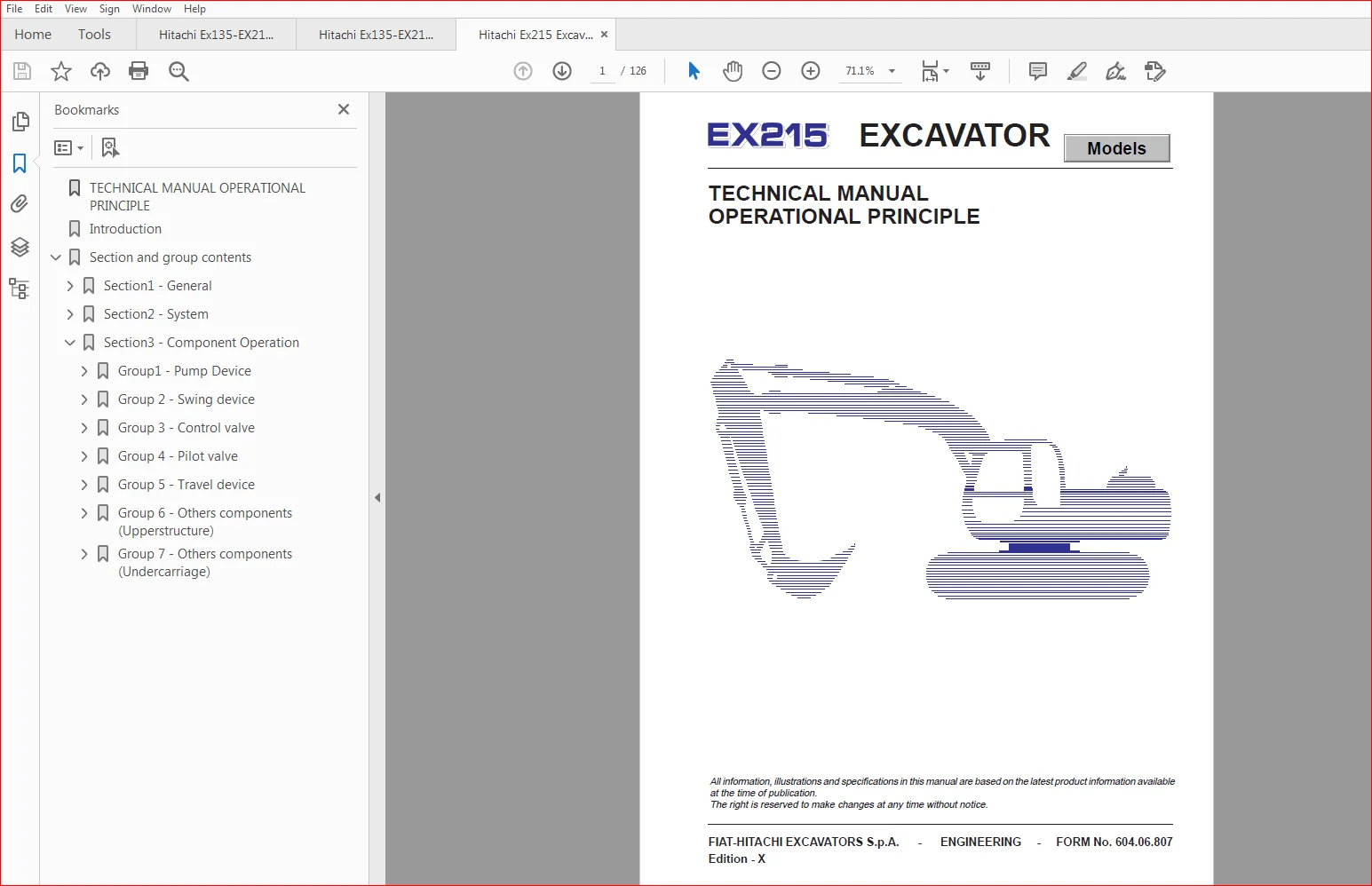
- Hitachi Ex215 Excavator Technical Operational Principle Manual
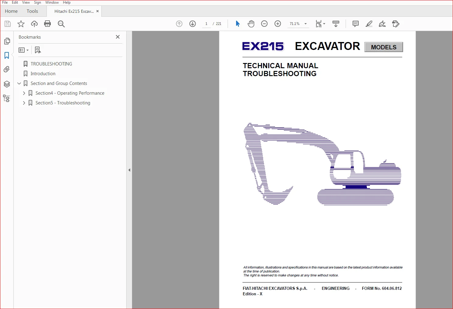
- Hitachi Ex215 Excavator Technical Troubleshooting Manual
- Hitachi Ex215 Excavator Technical Workshop Manual
Description
Hitachi EX215 Excavator Operational Principle+Troubleshooting+Workshop Manual – Hitachi EX215
File Details:
Hitachi EX215 Excavator Operational Principle+Troubleshooting+Workshop Manual – Hitachi EX215
This Listing includes all of the manuals mentioned below:
Hitachi Ex135-EX215 Excavator Engine Technical Workshop Manual
Hitachi Ex215 Excavator Technical Operational Principle Manual
Hitachi Ex215 Excavator Technical Troubleshooting Manual
Hitachi Ex215 Excavator Technical Workshop Manual
HITACHI EX215 EXCAVATOR OPERATIONAL PRINCIPLE+TROUBLESHOOTING+WORKSHOP MANUAL – HITACHI EX215 – PDF DOWNLOAD:
Image Preview:
Description:
Hitachi EX215 Excavator Operational Principle+Troubleshooting+Workshop Manual – Hitachi EX215
TO THE READER
• This manual is written for an experienced technician to provide technical information needed to maintain and repair this machine.
– Be sure to thoroughly read this manual for correct information concerning the service procedures.
– If you have any questions or comments, or if you found any errors regarding the contents of this manual,
ADDITIONAL REFERENCES
• Please refer to the materials listed below in addition to this service manual:
– Operator’s Manual
– Spare Parts Catalog
SERVICE MANUAL COMPOSITION
• The complete service manual consists of four books:
– Technical Manual – Operational Principle
– Technical Manual – Troubleshooting
– Excavator Workshop Manual
– Engine Workshop Manual
– The Technical Manual-Operational Principle includes the technical information concerning the operation of main devices and systems.
– The Technical Manual -Troubleshooting includes the technical information needed for operational performance tests, and troubleshootingprocedures.
– The Excavator and the Engine Workshop Manuals include information needed for maintenance and repair of the machine, tools and devices needed for maintenance and repair, maintenance standards, removal/installation and assembly/disassembly procedures.
Table Of Contents:
Hitachi EX215 Excavator Operational Principle+Troubleshooting+Workshop Manual – Hitachi EX215
Hitachi Ex135-EX215 Excavator Engine Technical Workshop Manual
ENGINE..............................................................................................................  1
Introduction........................................................................................................  2
List of Sections....................................................................................................  4
	Section1 - Diagnostics..........................................................................................  5
		Diagnostics ................................................................................................  6
	Section2 - Removal & Installation Ex 135 Engine................................................................. 17
		Engine/Pumps Assembly Removal............................................................................... 18
			Air Conditioner......................................................................................... 21
			Electrical Connections.................................................................................. 21
			Hydraulic Pumps......................................................................................... 22
			Engine/Pumps Assembly Lifting........................................................................... 22
		Engine/Pumps Assembly Installation.......................................................................... 23
			Tightening Torques...................................................................................... 23
		Filling..................................................................................................... 24
			Fuel System Air Bleeding................................................................................ 25
			Filling The Cooling Sistem.............................................................................. 26
			Hydraulic System Oil Refilling.......................................................................... 27
	Section3 - Engine Ex 135 Overhaul............................................................................... 28
		Specifications and data..................................................................................... 30
		Mounting clearances - Data.................................................................................. 33
		Graphic Representation and Symbols.......................................................................... 40
		Tightening torques.......................................................................................... 41
		Special tools............................................................................................... 42
		Stripping down the engine in the Workshop................................................................... 44
		Repairs - Cylinder block - Checks and measurements.......................................................... 50
			Replacement of cylinder liners.......................................................................... 51
		Camshaft - Bushes - Valve Lifters........................................................................... 52
		Cam pitch and bearing journal alignment check............................................................... 53
		Driven toothed wheel replacement............................................................................ 53
		Bush replacement............................................................................................ 53
		Valve lifters............................................................................................... 54
			Replacement of valve lifters............................................................................ 54
			Mounting of valve lifters - camshaft.................................................................... 55
		Crankshaft.................................................................................................. 56
		Main and connecting rod bearing journals.................................................................... 56
		Check of main bearing journal alignment..................................................................... 57
		Replacement of driving toothed wheel steering and oil pump.................................................. 58
		Mounting of main bearings................................................................................... 58
		Checking of main bearing journal mounting clearance......................................................... 58
			Crankshaft end play check............................................................................... 59
		Rear flywheel cover......................................................................................... 60
		Engine flywhee.............................................................................................. 60
		Replacement of engine flywheel toothed wheel................................................................ 60
		Connecting rod ± piston assembly............................................................................ 61
		Piston...................................................................................................... 61
			Piston diameter measurement............................................................................. 61
		Piston pins................................................................................................. 62
		Piston rings................................................................................................ 63
		Connecting rods............................................................................................. 63
			Check of rectangularity of connecting rod............................................................... 64
		Bushes...................................................................................................... 64
		Mounting of connecting rod - piston assembly................................................................ 65
			Connecting rod - piston mating.......................................................................... 65
			Connecting rod - piston rectangularity check............................................................ 65
			Mounting of piston rings................................................................................ 65
		Adjustment of the mounting clearance of the connecting rod journals......................................... 66
			Mounting of connecting rod covers....................................................................... 67
		Steering.................................................................................................... 67
		Check and replacement of the transmission gear wheel........................................................ 67
		Replacement of bush for transmission gear wheel............................................................. 67
			Mounting of the transmission gear wheel and adjustment of the steering.................................. 68
		Cylinder head............................................................................................... 68
			Tightness check......................................................................................... 68
		Dismounting of valves....................................................................................... 69
			Check of cylinder head bearing surface on cylinder block................................................ 69
		Valves...................................................................................................... 69
		Removal of incrustration and valve check.................................................................... 69
			Valve grinding.......................................................................................... 70
			Boring of inner surfaces of valve stem guides........................................................... 70
			Check of clearance between valve spindle and valve stem guide........................................... 70
		Refinishing of valve seats.................................................................................. 71
			Valve sealing test...................................................................................... 71
			Remounting of valves.................................................................................... 71
			Mounting of cylinder head............................................................................... 72
		Rods........................................................................................................ 73
			Mounting of valve lifter shaft and adjustment of working clearance between valves and valve liftersi.... 74
		Lubrication................................................................................................. 74
		Oil pump.................................................................................................... 74
		Oil filter.................................................................................................. 76
			Oil pump assembly....................................................................................... 76
		Cooling system.............................................................................................. 76
		Water pump.................................................................................................. 76
		Thermostat.................................................................................................. 76
			Carrying out engine assembly at work bench.............................................................. 77
		Injection pump installation and timing...................................................................... 77
		Adjustment of the driving belt tension: water pump ± generator and fan...................................... 79
		Turbocharger................................................................................................ 82
			Description............................................................................................. 82
			Necessary checks before dismounting the turbocharger from the engine.................................... 83
		Dismounting................................................................................................. 83
			Checks.................................................................................................. 85
			Mounting................................................................................................ 86
		Fuel feed................................................................................................... 88
			Dismounting............................................................................................. 88
		Calibration................................................................................................. 88
		Injection pump.............................................................................................. 89
		Marking..................................................................................................... 89
		BOSCH stock number.......................................................................................... 89
		Mode of operation........................................................................................... 90
			Feed step............................................................................................... 90
			Delivery................................................................................................ 90
			Automatic injection adjustment.......................................................................... 91
			Starting device disconnected............................................................................ 92
			Load±dependent feed start (L.F.B.)...................................................................... 93
			Description............................................................................................. 93
			Position of the governor collar in the LFB.............................................................. 94
			L.D.A. device (load±dependent feed adjustment).......................................................... 95
			Mode of operation....................................................................................... 94
			Dismounting of the injection pump....................................................................... 95
		Checks .....................................................................................................101
			Check of pressure increasing control valve..............................................................108
			Pre±adjustment of the adjustment screw for the L.D.A. device............................................109
			Lift adjustment of the L.D.A. device....................................................................110
			Adjustment of the starting dimension "MS" (only engine 8040.45).........................................112
			Calibration tables......................................................................................114
	Section4 - Removal & Installation Ex215 Engine..................................................................118
		Engine/Pumps Assembly Removal...............................................................................119
			Air Conditioner.........................................................................................122
			Electrical Connections..................................................................................122
			Hydraulic Pumps.........................................................................................123
			Engine/Pumps Assembly Lifting...........................................................................123
		Engine/Pumps Assembly Installation..........................................................................124
			Tightening Torques......................................................................................124
		Filling.....................................................................................................125
			Fuel System Air Bleeding................................................................................126
			Filling The Cooling Sistem..............................................................................127
			Hydraulic System Oil Refilling..........................................................................128
	Section5 - Engine Ex215 Overhaul................................................................................129
		Specifications and data.....................................................................................131
		Fitting data................................................................................................134
		Graphic Representations and Symbols.........................................................................141
		Tightening torques..........................................................................................142
		Tools.......................................................................................................143
		Stripping down the engine in the workshop...................................................................145
		Repeirs Cylinder block Checks and measurements..............................................................150
		Replacement of cylinder liners..............................................................................151
		Camshaft....................................................................................................152
		Bushes - valve lifters......................................................................................152
		Cam pitch and bearing journal alignment check...............................................................152
		Driven toothed wheel replacement............................................................................152
		Bushes......................................................................................................153
		Bush replacement............................................................................................153
		Valve lifters...............................................................................................154
		Replacement of valve lifters................................................................................154
			Mounting of valve lifters - Camshaft....................................................................154
		Crankshaft..................................................................................................155
		Main and connecting rod bearing journals....................................................................156
		Check of main bearing journal alignment.....................................................................157
		Replacement of driving toothed wheel steering and oil pump..................................................157
		Mounting of main bearings...................................................................................158
			Crankshaft end play check...............................................................................158
		Rear flywheel cover.........................................................................................160
		Engine flywheel.............................................................................................160
		Replacement of engine flywheel toothed wheel................................................................160
			Mounting of engine flywheel.............................................................................160
		Connecting rod -piston assembly.............................................................................160
		Piston......................................................................................................161
			Piston diameter measurement.............................................................................161
		Piston pin..................................................................................................161
			Check of correct fit between piston pin and piston......................................................161
		Piston rings................................................................................................162
		Connecting rods.............................................................................................163
			Check of rectangularity of connecting rod...............................................................164
		Bushes......................................................................................................164
		Mounting of connecting rod - piston assembly................................................................164
			Connecting rod -piston mating...........................................................................164
			Mounting of piston rings................................................................................165
		Adjustment of the mounting clearance of the connecting rod journals.........................................166
			Mounting of connecting rod covers.......................................................................166
		Steering....................................................................................................166
		Check and replacement of the transmission gear wheel........................................................166
		Replacement of bush for transmission gear wheel.............................................................167
			Mounting of the transmission gear wheel and adjustment of the steering..................................167
		Cylinder head...............................................................................................168
			Tightness check.........................................................................................168
		Dismounting of valves.......................................................................................168
			Check of cylinder head bearing surface on cylinder block................................................168
		Valves......................................................................................................169
		Removal of incrustration and valve check....................................................................169
			Valve grinding..........................................................................................169
			Check of clearance between valve spindle and valve stem guide...........................................169
		Valve stem guide............................................................................................169
			Boring of inner surfaces of valve stem guides...........................................................170
			Remounting of valves....................................................................................171
			Mounting of cylinder head...............................................................................171
			Mounting of valve lifter shaft and adjustment of working clearance between valves and valve lifters.....173
		Lubrification...............................................................................................174
		Oil pump....................................................................................................174
		Oil filter..................................................................................................176
			Oil pump assembly.......................................................................................176
		Cooling system..............................................................................................176
		Water pump..................................................................................................176
		Thermostat..................................................................................................177
			Carrying out engine assembly at work bench..............................................................177
		Injection pump installation and timing......................................................................177
		Adjustment of the tension of control belts: water pump - generator and fan..................................178
		Turbocharger................................................................................................181
			Description.............................................................................................181
			Necessary checks before dismounting the turbocharger from the engine....................................181
		Dismounting.................................................................................................182
			Checks..................................................................................................183
			Mounting................................................................................................185
		Fuel system.................................................................................................187
		Injectors...................................................................................................187
			Calibration.............................................................................................187
			Dismantling.............................................................................................187
		Injection pump with RSV speed governor......................................................................188
			L.D.A. device (delivery adjustment as a function of load)...............................................188
			Pump marking............................................................................................188
			Speed governor marking..................................................................................188
			Speed governor..........................................................................................188
			High -pressure pumping elements.........................................................................188
			Delivery valves.........................................................................................189
			Pressure control valve assembly.........................................................................189
			Fuel injector units.....................................................................................189
			Calibration tables......................................................................................191
	Section6 - Recharge and Start - Up .............................................................................194
		Starter Motor...............................................................................................195
			Quick diagnosis.........................................................................................195
			Magneti Marelli MT 67CB - 4kW...........................................................................196
			Test and checks on the vehicle Current absorption test..................................................197
			Voltage drop test on the circuit........................................................................197
			Excessive voltage drop test on the circuit..............................................................197
			Starter motor earth test................................................................................198
			Voltage drop test on the solenoid contacts..............................................................198
			Disassembly.............................................................................................199
			Assembly................................................................................................199
			Bench test..............................................................................................200
		Alternator..................................................................................................201
			Quick diagnosis.........................................................................................201
			Bosch   NL1  28V  10/55A................................................................................202
		Test and Checks the Vehicle.................................................................................203
			Maximum output test.....................................................................................203
			Pressure drop test on the circuit.......................................................................203
			Voltage drop test on the earth circuit..................................................................204
			Voltage regulator calibration test......................................................................204
			Alternator belt tensioning..............................................................................204
			Disassembly and bench test..............................................................................205
			Assembly................................................................................................205

Hitachi Ex215 Excavator Technical Operational Principle Manual
TECHNICAL MANUAL OPERATIONAL PRINCIPLE............................  1
Introduction......................................................  2
Section and group contents .......................................  4
	Section1 - General............................................  5
		Group1 - Specification....................................  6
			Excavator Dimensions (Monoblock version)..............  6
			Excavator Dimensions (Triple articulation version)....  7
			Excavator performance.................................  8
			Engine................................................  8
			Engine accessory......................................  8
			Hydraulic Device......................................  9
			Electrical Equipment.................................. 10
		Group2 - Component Layout................................. 12
			Main components....................................... 12
			Electrical system (Overall system).................... 13
			Electrical system (Relays)............................ 14
			Electrical system (Monitor and Switch panels)......... 15
			Electrical system (Fuses)............................. 16
			Pump and related parts................................ 17
			Other components...................................... 18
	Section2 - System............................................. 20
		Group1 - Control System................................... 21
			Outline............................................... 21
			Engine control........................................ 22
			Pump control.......................................... 28
			Valve control......................................... 30
			Other control function................................ 34
		Group2 - Hydraulic System................................. 35
			Main circuit.......................................... 35
			Pilot circuit......................................... 36
			Neutral circuit....................................... 37
			Single actuator operation............................. 37
			Combined operation.................................... 38
		Group3 - Electrical System................................ 41
			Outline............................................... 41
			Electric power circuit................................ 42
			Bulb check circuit.................................... 43
			Intake air heater circuit............................. 44
			Starting circuit...................................... 46
			Charging circuit...................................... 48
			Surge voltage prevention circuit...................... 49
			Accessory circuit..................................... 50
			Engine stop circuit................................... 51
			Engine emergency stop................................. 52
	Section3 - Component Operation................................ 54
		Group1 - Pump Device...................................... 55
			Outline............................................... 55
			Main pump............................................. 56
			Regulator............................................. 59
			Pilot pump............................................ 67
			N sensor (Engine speed sensor)........................ 67
			Pump pressure sensor.................................. 67
		Group 2 - Swing device.................................... 69
			Outline............................................... 69
			Swing motor........................................... 70
			Brake valve........................................... 72
			Swing parking brake................................... 74
			Swing reduction gear.................................. 75
		Group 3 - Control valve................................... 77
			Outline............................................... 77
			Hydraulic circuit..................................... 82
			Flow combiner valve................................... 84
			Pump control valve.................................... 86
			Main relief valve..................................... 88
			Overload relief valve................................. 89
			Arm regenerative valve................................ 90
			Boom anti-drift valve, arm anti-drift valve........... 92
			Bucket flow control valve............................. 92
			Travel flow control valve............................. 94
			Travel/boom lower selector valve...................... 94
			Boom regenerative valve............................... 96
		Group 4 - Pilot valve..................................... 97
			Outline............................................... 97
			Operation............................................. 99
		Group 5 - Travel device...................................107
			Outline...............................................107
			Travel reduction gear.................................108
			Travel motor..........................................109
			Travel brake valve....................................113
			Parking brake.........................................115
		Group 6 - Others components (Upperstructure)..............117
			Pilot shut-off valve..................................117
			Shockless valve.......................................118
			Solenoid valve unit...................................120
			Pilot relief valve....................................122
			EC motor..............................................122
		Group 7 - Others components (Undercarriage)...............123
			Swing bearing.........................................123
			Center joint..........................................124
			Track adjuster........................................125
Hitachi Ex215 Excavator Technical Troubleshooting Manual
TROUBLESHOOTING..................................................................... 1
Introduction........................................................................ 2
Section and Group Contents.......................................................... 28
Section4 - Operating Performance................................................ 29
Group 1 - Introduction...................................................... 30
Operational performance test............................................ 30
Preparation for performance tests....................................... 31
Group 2 - Standard.......................................................... 32
Operational Performance standard tables................................. 32
Main pump P-Q diagram................................................... 36
Group 3 - Engine test....................................................... 38
Engine speed............................................................ 38
Group 4 - Excavator test.................................................... 40
Travel speed............................................................ 40
Track revolution speed.................................................. 41
Mistrack check.......................................................... 42
Travel parking function check........................................... 43
Swing speed............................................................. 44
Swing function drift check.............................................. 45
Swing motor leakage..................................................... 46
Swing bearing play...................................................... 47
Maximum swingable slant angle........................................... 48
Hydraulic cylinder cycle time........................................... 49
Dig function drift check................................................ 51
Control lever operating force........................................... 52
Control lever stroke.................................................... 53
Combined boom raise/swing function check................................ 54
Group 5 - Component test.................................................... 56
Primary pilot pressure.................................................. 56
Secondary pilot pressure................................................ 58
Solenoid valve set pressure............................................. 59
Main pump delivery pressure............................................. 61
Main relief valve set pressure.......................................... 62
Overload relief valve set pressure...................................... 66
Main pump flow test..................................................... 69
Swing motor drainage.................................................... 73
Travel motor drainage................................................... 75
Section5 - Troubleshooting...................................................... 78
Group 1 - Diagnosing Procedure.............................................. 80
Introduction............................................................ 80
Diagnosing Procedure.................................................... 81
Dr.EX................................................................... 83
Dr.EX Start-Up Procedure................................................ 83
Dr.EX Fault Code........................................................ 84
Dr.EX Monitoring Function............................................... 85
Dr.EX Special Function (Service Mode)................................... 86
Adjustable Data List.................................................... 93
Group 2 - Component Layout.................................................. 94
Main Components......................................................... 94
Electrical System (Overall System)...................................... 95
Electrical System (Relays).............................................. 96
Electrical System (Monitor and Switch Panels).......................... 97
Pump and Related Parts.................................................. 98
Control Valve........................................................... 99
Others Components.......................................................103
Group 3 - Troubleshooting A.................................................104
Troubleshooting A Procedure ............................................104
Fault Codes.............................................................105
Fault Code 01...........................................................107
Fault Code 02, 03.......................................................108
Fault Code 04, 05.......................................................109
Fault Code 06...........................................................110
Fault Code 07...........................................................111
Sensor Operating Range List.............................................112
Group 4 - Troubleshooting B.................................................114
Troubleshooting B Procedure.............................................114
Relationship between Machine Trouble Symptoms and Parts in Trouble.....115
Correlation between Trouble Symptoms and Part Failures.................125
Engine Troubleshooting..................................................131
Actuator Control System Troubleshooting................................145
Front Attachment Control System Troubleshooting........................151
Swing System Troubleshooting............................................163
Travel System Troubleshooting...........................................166
Troubleshooting for Other Functions.....................................171
Engine Speed Adjustment and Engine Learning............................173
Exchange Inspection Method..............................................174
Group 5 - Troubleshooting C.................................................176
Troubleshooting C Procedure.............................................176
Malfunction of Coolant Temperature Gauge................................177
Malfunction of Fuel Gauge...............................................179
Malfunction of Fuel Level Indicator.....................................181
Malfunction of Indicator Light Check System.............................183
Malfunction of Level Check Switch.......................................183
Malfunction of Engine Oil Level Indicator...............................185
Malfunction of Coolant Level Indicator..................................187
Malfunction of Hydraulic Oil Level Indicator............................189
Malfunction of Alternator Indicator.....................................191
Malfunction of Engine Oil Pressure Indicator............................193
Malfunction of Overheat Indicator.......................................195
Malfunction of Air Filter Restriction Indicator.........................197
Malfunction of Buzzer...................................................199
Malfunction of Hour Meter...............................................201
Group 6 - Electrical System Inspection......................................202
Precautions for Inspection and Maintenance.............................202
Instructions for Disconnecting Connectors...............................204
Fuse Continuity Test....................................................205
Inspection and Replacement of Fusible Links.............................206
Battery Voltage Check...................................................207
How to Troubleshoot Alternator Malfunctions.............................208
Continuity Check........................................................209
Voltage and Current Check...............................................211
Replacement of Relay....................................................215
Group 7 - Harness Check.....................................................216
Circuit Check...........................................................216
Hitachi Ex215 Excavator Technical Workshop ManualEXCAVATORS........................................................................... 1 Introduction......................................................................... 2 Section and Group Contents........................................................... 28 Section1 - General Information................................................... 29 Group 1 -Precautions for Disassembling and Assembling........................ 30 Precautions for Disassembling and Assembling............................. 30 Group 2 -Tightening Torque................................................... 34 Tightening Torque Specification.......................................... 34 Torque Chart............................................................. 35 Pipe Thread Connection / Union joint Tightening Torque Specifications.... 38 Section2 - Upperstructure........................................................ 42 Group 1 - Cab................................................................ 43 Remove and Install Cab................................................... 43 Group 2 - Counterweight...................................................... 49 Remove and Install Counterweight......................................... 49 Group 3 - Main Frame......................................................... 51 Remove and Install Main Frame............................................ 51 Group 4 - Pump Device........................................................ 59 Remove and Instal Pump Device............................................ 59 Disassemble Pump Device.................................................. 60 Assemble Pump Device..................................................... 68 Disassemble Regulator.................................................... 80 Assemble Regulator....................................................... 82 Disassemble and Assemble Pilot Pump...................................... 84 Maintenance Standard..................................................... 86 Group 5 - Control Valve...................................................... 89 Remove and Instal Control Valve.......................................... 89 Disassemble Control Valve 1............................................. 90 Assemble Control Valve 1-1............................................... 94 Assemble Control Valve 1-2............................................... 96 Disassemble Control Valve 2.............................................. 98 Assemble Control Valve 2-1...............................................102 Assemble Control Valve 2-2...............................................104 Disassemble Control Valve 3..............................................106 Assemble Control Valve 3-1...............................................110 Assemble Control Valve 3-2...............................................114 Disassemble Control Valve 4..............................................116 Assemble Control Valve 4-1...............................................120 Assemble Control Valve 4-2...............................................122 DisassembleControl Valve 5...............................................126 Assemble Control Valve 5.................................................128 Group 6 - Swing Device.......................................................131 Remove and Install Swing Device..........................................131 Disassemble Swing Device.................................................132 Assemble Swing Device....................................................136 Disassemble Swing Motor..................................................142 Assemble Swing Motor.....................................................146 Maintenance Standard.....................................................150 Group 7 - Pilot Valve........................................................153 Remove and Install Right Pilot Valve.....................................153 Remove and Install Left Pilot Valve......................................156 Remove and Install Travel Pilot Valve....................................159 Disassemble Right and Left Pilot Valve...................................160 Assemble Right and Left Pilot Valve......................................162 Disassemble Travel Pilot Valve...........................................166 Assemble Travel Pilot Valve..............................................168 Group 8 - Pilot Shut-Off Valve...............................................185 Remove and Install Pilot Shut-off Valve..................................185 Disassemble Pilot Shut-off Valve.........................................186 Assemble Pilot Shut-off Valve............................................188 Group 9 - Shockless Valve....................................................191 Remove and Install Shockless Valve.......................................191 Disassemble and Assemble Shockless Valve.................................192 Group 10 - Solenoid Valve....................................................195 Remove and Install Solenoid Valve Unit...................................195 Disassemble Propotional Solenoid Valve...................................196 Assemble Propotional Solenoid Valve......................................198 Group 11- Pilot Relief Valve Unit............................................201 Remove and Install Pilot Relief Valve Unit...............................201 Disassemble Pilot Relief Valve...........................................202 Assemble Pilot Relief Valve..............................................204 Section3 - Undercarriage.........................................................207 Group 1 - Swing Bearing......................................................208 Remove and Install Swing Bearing.........................................208 Group 2 - Travel Device......................................................210 Remove and Install Travel Device.........................................210 Disassemble Travel Device................................................211 Assemble Travel Device...................................................217 Disassemble Travel Motor.................................................223 Assemble Travel Motor....................................................227 Disassemble Brake Valve..................................................235 Assemble Brake Valve.....................................................237 Maintenance Standard.....................................................239 Remove and Install Travel Device (EX215 - EX215 E).......................242 Travel Motor Removal.....................................................243 Travel Reduction Gear Disassembly........................................244 Reassembly...............................................................249 Travel Motor Reassembing.................................................255 Group 3 - Center Joint.......................................................258 Remove and Install Center Joint..........................................258 Disassemble Center Joint.................................................259 Assemble Center Joint....................................................261 Maintenance Standard.....................................................264 Group 4 - Track Adjuster.....................................................266 Remove and Install Track Adjuster........................................266 Disassemble Track Adjuster...............................................267 Assemble Track Adjuster..................................................275 Group 5 - Front Idler........................................................282 Remove and Install Front Idler...........................................282 Disassemble Front Idler..................................................283 Assemble Front Idler.....................................................287 Maintenance Standard.....................................................289 Group 6 - Upper and Lower Roller.............................................290 Remove and Install Upper Roller..........................................290 Remove and Install Lower Roller..........................................293 Disassemble Upper Roller.................................................296 Disassemble Lower Roller.................................................297 Assemble Lower Roller....................................................299 Maintenance Standard.....................................................301 Group 7 - Track..............................................................304 Remove and Install Track.................................................304 Maintenance Standard.....................................................308 Section4 - Front Attachment......................................................310 Group 1 - Front attachment...................................................311 Remove and install front attachment......................................311 Maintenance Standard (monobloc version)..................................316 Bucket teeth.............................................................318 Standard dimensions for arm and bucket connection........................319 Remove and install front attachment (triple articulation version)........321 Maintenance Standard (triple articulation version).......................326 Group 2 - Cylinders..........................................................329 Remove and install cylinders.............................................329 Hydraulic circuit pressure release procedure.............................340 Disassemble cylinders....................................................342 Assemble cylinders.......................................................348 Maintenance Standard.....................................................354 Special Tools............................................................355
Please Note:
- This is the SAME exact manual used by your dealers to fix your vehicle.
- The same can be yours in the next 2-3 mins as you will be directed to the download page immediately after paying for the manual.
- Any queries / doubts regarding your purchase, please feel free to contact [email protected]