Hitachi EX2600-7B Hydraulic Excavator Tier 4 Final Cummins Engine Workshop Manual PDF
$34.95
Hitachi EX2600-7B Hydraulic Excavator Tier 4 Final Cummins Engine Workshop Manual – PDF DOWNLOAD
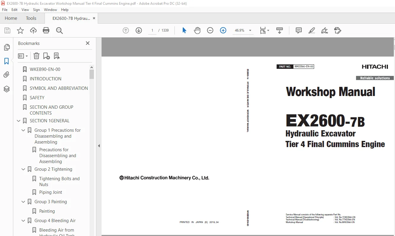
Service Manual consists of the following separate Part No.
Technical Manual (Operational Principle) : Vol. No.TOKEB90-EN
Technical Manual (Troubleshooting) : Vol. No.TTKEB90-EN
Workshop Manual : Vol. No.WKEB90-EN
Description
Hitachi EX2600-7B Hydraulic Excavator Tier 4 Final Cummins Engine Workshop Manual – PDF DOWNLOAD
FILE DETAILS:
Hitachi EX2600-7B Hydraulic Excavator Tier 4 Final Cummins Engine Workshop Manual – PDF DOWNLOAD
Language :English
Pages :1339
Downloadable : Yes
File Type : PDF
IMAGES PREVIEW OF THE MANUAL:
DESCRIPRION:
Hitachi EX2600-7B Hydraulic Excavator Tier 4 Final Cummins Engine Workshop Manual – PDF DOWNLOAD
Service Manual consists of the following separate Part No.
Technical Manual (Operational Principle) : Vol. No.TOKEB90-EN
Technical Manual (Troubleshooting) : Vol. No.TTKEB90-EN
Workshop Manual : Vol. No.WKEB90-EN
- This manual is written for an experienced technician to provide technical information needed to maintain and repair this machine. The machine specification and description according to destination may be explained on this manual.
- Be sure to thoroughly read this manual for correct product information and service procedures
- If you have any questions or comments, at if you found any errors regarding the contents of this manual, please contact using “Service Manual Revision Request Form” at the end of this manual. (Note: Do not tear off the form. Copy it for usage.):
Manual Composition
- This manual consists the Technical Manual and the Workshop Manual
- Information included in the Technical Manual: Technical information needed for redelivery and delivery, operation and activation of all devices and systems, operational performance tests, and troubleshooting procedures.
- Information included in the Workshop Manual: Technical information needed for maintenance and repair of the machine, tools and devices needed for maintenance and repair, maintenance standards, and removal / installation and assemble / disassemble procedures.
TABLE OF CONTENTS:
Hitachi EX2600-7B Hydraulic Excavator Tier 4 Final Cummins Engine Workshop Manual – PDF DOWNLOAD
Service Manual consists of the following separate Part No.
Technical Manual (Operational Principle) : Vol. No.TOKEB90-EN
Technical Manual (Troubleshooting) : Vol. No.TTKEB90-EN
Workshop Manual : Vol. No.WKEB90-EN
WKEB90-EN-00 1
INTRODUCTION 3
SYMBOL AND ABBREVIATION 5
SAFETY 7
SECTION AND GROUP CONTENTS 51
SECTION 1GENERAL 55
Group 1 Precautions for Disassembling and Assembling 57
Precautions for Disassembling and Assembling 57
Group 2 Tightening 63
Tightening Bolts and Nuts 63
Piping Joint 66
Group 3 Painting 73
Painting 73
Group 4 Bleeding Air 75
Bleeding Air from Hydraulic Oil Tank 75
Bleeding Air from Hydraulic System 77
Bleeding Air from Fuel System 83
Bleeding Air from Water Tank 85
Group 5 Releasing Pressure 87
Releasing Pressure in Hydraulic Circuit 87
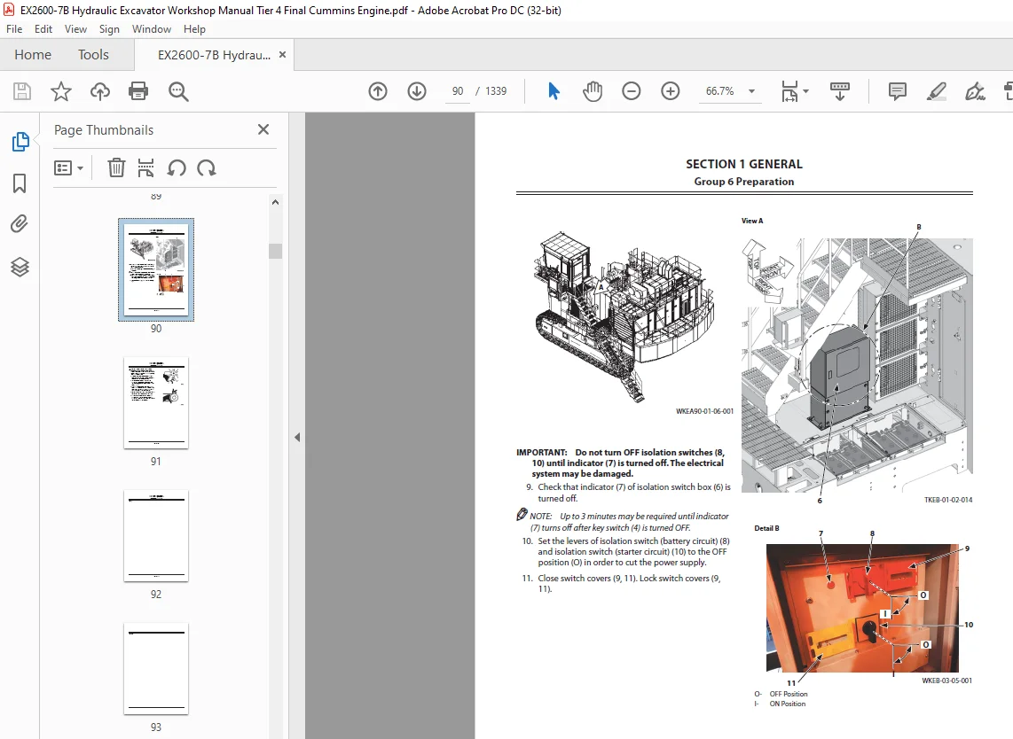
Group 6 Preparation 89
Preparation before Inspection and Maintenance 89
SECTION 2MAINTENANCE STANDARD 95
Group 1 Upperstructure 97
Pump Device 97
Swing Motor 101
Group 2 Undercarriage 105
Travel Motor 105
Drive Tumbler 109
Front Idler 111
Upper Roller 113
Lower Roller 115
Track 117
Group 3 Loader Front Attachment 119
Pin and Bushing 119
Point (4699753) 121
Point (YA00033975) 122
Shroud 123
Cylinder 125
Group 4 Backhoe Front Attachment 127
Pin and Bushing 127
Point, Shroud 129
Cylinder 131
SECTION 3UPPERSTRUCTURE 135
Group 1 Cab 137
Removal and Installation of Cab 137
Dimensions of Cab Glass 165
Removal and Installation of Escape Device 171
Group 2 Cab Bed 173
Removal and Installation of Cab Bed 173
Removal and Installation of Cab Bed Blower Motor 197
Removal and Installation of Air Conditioner Unit 199
Removal and Installation of Air Conditioner Compressor Motor 207
Disassembly of Air Conditioner Compressor Motor 213
Removal and Installation of Air Conditioner Compressor 221
Removal and Installation of Air Conditioner Condenser 225
Work When Replacing Components of Air Conditioner 229
Recover Refrigerant 230
Refill Compressor Oil 231
Charge Air Conditioner with Refrigerant 232
Group 3 Counterweight 241
Removal and Installation of Counterweight 241
Group 4 Upperstructure 251
Removal and Installation of Upperstructure 251
Removal and Installation of Folding Stairway 271
Removal and Installation of Left Fender 281
Removal and Installation of Right Fender 307
Group 5 Engine Unit 317
Removal and Installation of Engine Unit Module 317
Preparation 318
Disconnection of Wire Harness (Control Box) in Pump Compartment (Rear Side) 319
Disconnection of Wire Harness (Starter Motor, Prelube Motor, ECM, etc) in Engine Compartment (Right Rear Side) 320
Disconnection of Wire Harness (Radiator, Fuel Filter) in Engine Compartment (Left Rear Side) 322
Disconnection of Wire Harness (Alternator, ECM) in Engine Compartment (Front Side) 324
Disconnection of Hydraulic Piping (Delivery, Return) 325
Disconnection of Hydraulic Piping (Suction, Pilot) and Fuel Piping 327
Disconnection of Fast-Filling Piping and DEF Piping 329
Removal of Handrail, Step, Door 333
Removal of Fender 335
Removal of Engine Unit Module 337
Installation of Engine Unit Module 339
Installation of Fender 342
Installation of Handrail, Step, Door 344
Connection of Fast-Filling Piping and DEF Piping 346
Connection of Hydraulic Piping (Suction, Pilot) and Fuel Piping 350
Connection of Hydraulic Piping (Delivery, Return) 352
Connection of Wire Harness (Alternator, ECM) in Engine Compartment (Front Side) 354
Connection of Wire Harness (Radiator, Fuel Filter) in Engine Compartment (Left Rear Side) 355
Connection of Wire Harness (Starter Motor, Prelube Motor, ECM, etc) in Engine Compartment (Right Rear Side) 357
Connection of Wire Harness (Control Box) in Pump Compartment (Rear Side) 360
Work after Installation 361
Removal and Installation of Engine 363
Preparation 364
Removale of Related Parts 366
Removale of Upper Covers 368
Disconnection of Hoses and wire Harnesses 372
Removale of Covers, Beams and Stays 379
Removale of Engine 384
Installation of Engine 387
Installation of Covers, Beams and Stays 390
Connection of Hoses and Harnesses 395
Installation of Upper Covers 402
Installation of Related Parts 406
Work after Installation 408
Removal and Installation of Radiator 409
Preparation 410
Removale of Related Parts 411
Disconnection of Hoses and Wire Harness 417
Removale of Radiator 419
Installation of Radiator 421
Connection of Hoses and Wire Harness 423
Installation of Related Parts 425
Work after Installation 432
Removal and Installation of Oil Cooler Core 433
Removal and Installation of Oil Cooler Fan Motor 451
Structure of Oil Cooler Fan Motor 479
Group 6 Pump Device 481
Removal and Installation of Pump Device 481
Preparation 482
Removal of Related Parts 484
Removal of Hoses 488
Removal of Electrical Parts 492
Removal of Pump Device 498
Installation of Pump Device 503
Installation of Electrical Parts 509
Installation of Hoses 516
Installation of Related Parts 521
Work after Installation 525
Disassembly and Assembly of Pump Transmission 527
Disassembly and Assembly of Main Pump 539
Disassembly and Assembly of Regulator for Main Pump 555
Structure of 4-Unit Pump 561
Disassembly and Assembly of Oil Cooler Fan Motor Pump 563
Disassembly and Assembly of Regulator for Oil Cooler Fan Motor Pump 577
Structure of Air Conditioner Compressor Motor Pump, Pilot Pump 589
Structure of Pump Transmission Oil Pump 593
Group 7 Control Valve 595
Removal and Installation of Control Valve (Loading Shovel) 595
Removal and Installation of Control Valve (Backhoe) 632
Disassembly and Assembly of Control Valve 669
Group 8 Other Valves 690
Removal and Installation of EDQR Valve 690
Structure of EDQR Valve 696
Structure of Proportional Solenoid Valve 700
Group 9 Swing Device 702
Removal and Installation of Swing Device 702
Disassembly and Assembly of Swing Reduction Gear 718
Disassembly and Assembly of Swing Motor 746
Disassembly and Assembly of Valve Unit 770
Group 10 Aftertreatment Device 776
Removal and Installation of Urea SCR Muffler Unit 776
Removal and Installation of DEF Tank 788
Removal and Installation of DEF Hose 804
Layout of Cover 805
Layout of DEF Hose 806
Group 11 Hydraulic Oil Tank 808
Removal and Installation of Hydraulic Oil Tank 808
Group 12 Fuel Tank 832
Removal and Installation of Fuel Tank 832
Group 13 Lift Cylinder (Fast-Filling System) 848
Removal and Installation of Lift Cylinder (Fast-Filling System) 848
Disassembly of Lift Cylinder (Fast-Filling System) 854
Assembly of Lift Cylinder (Fast-Filling System) 856
Group 14 Lift Cylinder (Folding Stairway) 858
Removal and Installation of Lift Cylinder (Folding Stairway) 858
Disassembly of Lift Cylinder (Folding Stairway) 866
Assembly of Lift Cylinder (Folding Stairway) 868
SECTION 4UNDERCARRIAGE 872
Group 1 Swing Bearing 874
Removal and Installation of Swing Bearing 874
Group 2 Travel Device 882
Removal and Installation of Travel Device 882
Disassembly and Assembly of Travel Reduction Gear 894
Disassembly and Assembly of Travel Motor 914
Disassembly and Assembly of Travel Mode Selector Valve 932
Group 3 Travel Brake Valve 940
Removal and Installation of Travel Brake Valve 940
Disassembly and Assembly of Travel Brake Valve 946
Group 4 Drive Tumbler 950
Removal and Installation of Drive Tumbler 950
Group 5 Center Joint 962
Removal and Installation of Center Joint 962
Disassembly of Center Joint 982
Assembly of Center Joint 986
Group 6 Adjuster Cylinder 992
Removal and Installation of Adjuster Cylinder 992
Disassembly of Adjuster Cylinder1000
Disassembly of Adjuster Cylinder1003
Group 7 Front Idler1008
Removal and Installation of Front Idler1008
Disassembly of Front Idler1010
Assembly of Front Idler1013
Group 8 Upper and Lower Roller1018
Removal and Installation of Upper Roller1018
Removal and Installation of Lower Roller1026
Disassembly of Upper Roller1034
Assembly of Upper Roller1037
Disassembly of Lower Roller1042
Assembly of Lower Roller1045
Group 9 Track1050
Removal and Installation of Track1050
Structure of Track1060
Group 10 Accumulator1062
Removal and Installation of Accumulator1062
Disassembly of Accumulator1072
Assembly of Accumulator1075
Charging Nitrogen Gas and Check1078
Group 11 Welding Repair Procedure1086
Welding Repair Procedure1086
Repair Track Shoes (Shoe Lugs)1088
Repair Rollers1092
Repair Drive Tumbler1096
SECTION 5LOADER FRONT ATTACHMENT1102
Group 1 Front Attachment1104
Removal and Installation of Bucket1104
Removal and Installation of Arm1114
Removal and Installation of Boom1130
Group 2 Cylinder1144
Removal and Installation of Boom Cylinders1144
Removal and Installation of Arm Cylinder1152
Removal and Installation of Bucket Cylinders1160
Removal and Installation of Level Cylinder1168
Removal and Installation of Dump Cylinders1176
Disassembly of Boom Cylinder1184
Assembly of Boom Cylinder1188
Disassembly of Arm Cylinder1194
Assembly of Arm Cylinder1198
Disassembly of Bucket Cylinder1204
Assembly of Bucket Cylinder1208
Disassembly of Level Cylinder1214
Assembly of Level Cylinder1218
Disassembly of Dump Cylinder1222
Assembly of Dump Cylinder1226
Bleeding Air Procedure1232
Group 3 Bushing1234
Removal and Installation of Bushing1234
Group 4 Angle Sensor1242
Removal and Installation of Angle Sensors1242
Group 5 Other Valves1252
Removal and Installation of 3-Spool Solenoid Valve Unit1252
Structure of 3-Spool Solenoid Valve Unit1256
Removal and Installation of Make-Up Valve1258
Disassembly of Make-Up Valve1260
Assembly of Make-Up Valve1262
SECTION 6BACKHOE FRONT ATTACHMENT1266
Group 1 Front Attachment1268
Removal and Installation of Bucket1268
Removal and Installation of Arm1274
Removal and Installation of Boom1282
Group 2 Cylinder1292
Removal and Installation of Boom Cylinders1292
Removal and Installation of Arm Cylinder1298
Removal and Installation of Bucket Cylinder1304
Disassembly and Assembly of Cylinder1310
Bleeding Air Procedures1312
Group 3 Bushing1314
Removal and Installation of Bushing1314
Group 4 Angle Sensor1322
Removal and Installation of Angle Sensors1322
Group 5 Other Valves1330
Removal and Installation of 3-Spool Solenoid Valve Unit1330
Removal and Installation of Make-Up Valve1334
THE ATTACHED PATTERN LIST1338
SERVICE MANUAL REVISION REQUEST FORM1339
S.M 1/2/25