Hitachi EX60-5 75UR-3 75URLC-3 Excavator Operational Principle+Troubleshooting+Workshop Manual – PDF DOWNLOAD
Original price was: $54.95.$24.95Current price is: $24.95.
Hitachi EX60-5 75UR-3 75URLC-3 Excavator Operational Principle+Troubleshooting+Workshop Manual
This Listing includes all of the manuals mentioned below:
- Hitachi EX60-5 75UR-3 75URLC-3 Excavator Operational Principle Technical Manual
- Hitachi EX60-5 75UR-3 75URLC-3 Excavator Troubleshooting Technical Manual
- Hitachi EX60-5 75UR-3 75URLC-3 Excavator Workshop Manual
- Hitachi EX60-5 75UR-3 75URLC-3 Excavator Circuit Diagram & Harness
Description
Hitachi EX60-5 75UR-3 75URLC-3 Excavator Operational Principle+Troubleshooting+Workshop Manual
FILE DETAILS:
Hitachi EX60-5 75UR-3 75URLC-3 Excavator Operational Principle+Troubleshooting+Workshop Manual
This Listing includes all of the manuals mentioned below:
- Hitachi EX60-5 75UR-3 75URLC-3 Excavator Operational Principle Technical Manual
- Hitachi EX60-5 75UR-3 75URLC-3 Excavator Troubleshooting Technical Manual
- Hitachi EX60-5 75UR-3 75URLC-3 Excavator Workshop Manual
- Hitachi EX60-5 75UR-3 75URLC-3 Excavator Circuit Diagram & Harness
DESCRIPTION:
Hitachi EX60-5 75UR-3 75URLC-3 Excavator Operational Principle+Troubleshooting+Workshop Manual
INTRODUCTION:
TO THE READER:
• This manual is written for an experienced technician to provide technical information needed to maintain and repair this machine.
• Be sure to thoroughly read this manual for correct product information and service procedures.
• If you have any questions or comments, at if you found any errors regarding the contents of this manual, please contact using “Service Manual Revision Request Form” at the end of this manual.
ADDITIONAL REFERENCES:
• Please refer to the materials listed below in addition to this manual.
• The Operator’s Manual
• The Parts Catalog
• The Engine Manual
• Parts Catalog of the Engine
• Hitachi Training Material
MANUAL COMPOSITION:
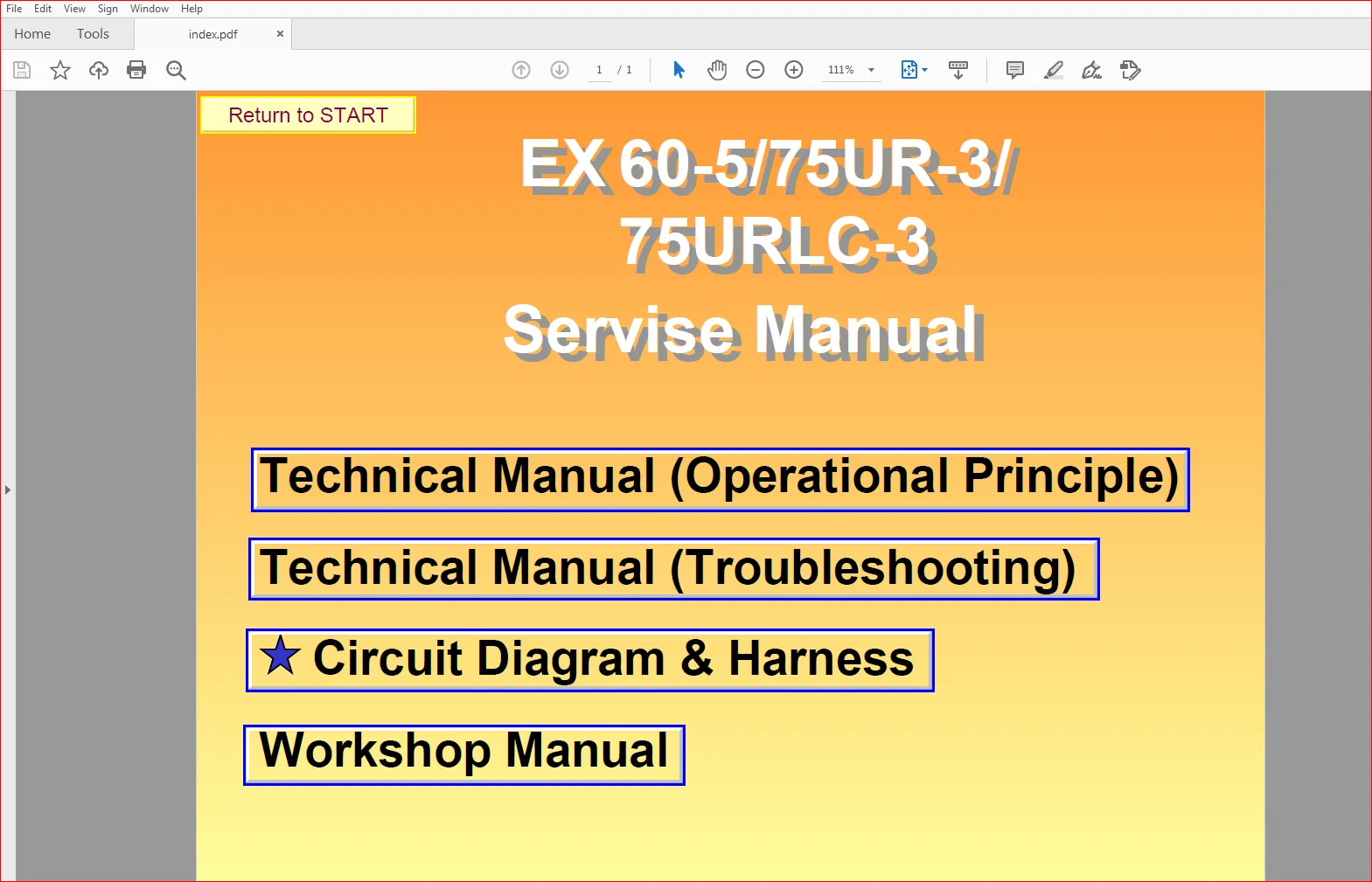
• This manual consists of three portions: the Technical Manual (Operational Principle), the Technical Manual (Troubleshooting) and the Workshop Manual.
• Information included in the Technical Manual (Operational Principle): technical information needed for redelivery and delivery, operation and activation of all devices and systems.
• Information included in the Technical Manual (Troubleshooting): technical information needed for operational performance tests, and troubleshooting procedures.
• Information included in the Workshop Manual: technical information needed for maintenance and repair of the machine, tools and devices needed for maintenance and repair, maintenance standards, and removal/installation and assemble/ disassemble procedures.
TABLE OF CONTENTS:
Hitachi EX60-5 75UR-3 75URLC-3 Excavator Operational Principle+Troubleshooting+Workshop Manual
- Hitachi EX60-5 75UR-3 75URLC-3 Excavator Troubleshooting Technical Manual
SECTION 4
OPERATIONAL
PERFORMANCE TEST
Group 1 Introduction
Operational Performance Tests T4-1-1
Preparation for Performance
Test T4-1-2
Group 2 Standard
Operational Performance
Standard Table T4-2-1
Main Pump P-Q Diagram T4-2-10
Sensor Activating Range T4-2-12
Group 3 Engine Test
Engine Speed T4-3-1
Engine Compression Pressure T4-3-2
Valve Clearance T4-3-4
Nozzle Check T4-3-6
Injection Timing T4-3-8
Group 4 Excavator Test
Travel Speed T4-4-1
Track Revolution Speed T4-4-2
Mistrack Check T4-4-3
Travel Motor Leakage T4-4-4
Swing Speed T4-4-5
Swing Function Drift Check T4-4-6
Swing Motor Leakage T4-4-7
Maximum Swingable
Slant Angle T4-4-8
Swing Bearing Play T4-4-9
Hydraulic Cylinder Cycle Time T4-4-10
Dig Function Drift Check T4-4-12
Control Lever Operating Force T4-4-13
Control Lever Stroke T4-4-14
Boom Raise/Swing Combined
Operation Check T4-4-15
Bucket /Cab Collision Prevention
System Check (EX75UR-3) T4-4-16
Group 5 Component Test
Primary Pilot Pressure T4-5-1
Secondary Pilot Pressure T4-5-3
Main Relief Valve Set Pressure T4-5-4
Overload Relief Valve Set Pressure T4-5-10
Main Pump Flow Rate Measurement T4-5-12
Swing Motor Drainage T4-5-16
Travel Motor Drainage T4-5-18
Group 6 Adjustment
Engine Speed Adjustment and
Engine Learning T4-6-1
Boom Lowering Method
when Engine Stalling T4-6-2
Check of Governor Lever and
Fuel Cut Lever Position T4-6-4
SECTION 5
TROUBLESHOOTING
Group 1 General
Introduction T5-1-1
Diagnostic Procedures T5-1-2
DrEX Operation T5-1-4
Main Controller Fault Code List T5-1-5
Auto-MARCCINO Control Unit
Fault Code List (EX75UR-3) T5-1-6
Main Controller Monitoring Function T5-1-8
Auto-MARCCINO Control Unit
Monitoring Function (EX75UR-3) T5-1-9
DrEX Special Function
(Service Mode) (EX75UR-3)T5-1-10
Group 2 Component Layout
Main Components T5-2-1
Electrical System
(Overview)T5-2-4
Electrical System
(Monitor and Switches) T5-2-11
Pump DeviceT5-2-15
Swing Device T5-2-15
Travel Device T5-2-16
Component in Control ValveT5-2-18
Group 3 Troubleshooting A
Troubleshooting A Procedure T5-3-1
Fault Code 01 (Abnormal EC Sensor)T5-3-2
Fault Code 07
(Abnormal Engine Control Dial Angle)T5-3-4
Group 4 Troubleshooting B
Troubleshooting B Procedure T5-4-1
Relationship between Machine Trouble
Symptoms and Suspected Parts T5-4-2
Correlation between Trouble
Symptoms and Part FailuresT5-4-6
Engine System Troubleshooting T5-4-12
All Actuator Control System
TroubleshootingT5-4-24
Front Attachment Control System
TroubleshootingT5-4-26
Swing System TroubleshootingT5-4-32
Travel System Troubleshooting T5-4-36
Blade System Troubleshooting T5-4-39
192T-5-2
Group 5 Troubleshooting C
Troubleshooting C Procedure
(Troubleshooting for Monitor)T5-5-1
Malfunction of Coolant Temperature
Gauge T5-5-2
Malfunction of Fuel GaugeT5-5-4
Malfunction of Indicator Light
Check System T5-5-6
Malfunction of Alternator Indicator T5-5-8
Malfunction of Engine Oil
Pressure Indicator T5-5-12
Malfunction of Overheat Indicator T5-5-16
Malfunction of Fuel Level Indicator
(EX75UR-3, EX75URLC-3) T5-5-20
Malfunction of Air Filter Restriction
Indicator T5-5-22
Malfunction of Electrolyte Level
Indicator(EX75UR-3, EX75URLC-3)T5-5-26
Malfunction of Buzzer T5-5-28
Malfunction of Hour Meter T5-5-32
Group 6 Troubleshooting D
Troubleshooting D Procedure
(EX75UR-3) T5-6-1
Auto-Marccino Control Unit
System Fault Code ListT5-6-2
Fault Code 03T5-6-4
Fault Code 07T5-6-5
Fault Code 08T5-6-5
Fault Code 11, 12, 13 T5-6-6
Fault Code 14, 15, 16, 20 T5-6-8
Fault Code 40, 41, 42, 44 T5-6-10
Fault Code 43, 45, 47 T5-6-11
Fault Code 50, 51, 52 T5-6-12
Fault Code 60, 61, 62 T5-6-14
Fault Code 80, 81, 82 T5-6-15
Fault Code 90T5-6-16
Group 7 Electrical System Inspection
Precautions for Inspection and
MaintenanceT5-7-1
Instructions for Disconnecting
Connectors T5-7-3
Fuse Continuity Test T5-7-4
Fusible Link Inspection T5-7-6
Battery Voltage CheckT5-7-7
How to Troubleshoot Alternator
Malfunctions T5-7-8
Continuity Check T5-7-9
Voltage and Current CheckT5-7-10
Check by False SignalT5-7-15
Test HarnessT5-7-16
- Hitachi EX60-5 75UR-3 75URLC-3 Excavator Workshop Manual
SECTION 1
GENERAL INFORMATION
Group 1 Precautions for Disassembling
and Assembling
Precautions for Disassembling and
Assembling W1-1-1
Maintenance Standard Terminology W1-1-7
Group 2 Tightening Torque
Tightening Torque Specification W1-2-1
Torque Chart W1-2-2
Piping Joint W1-2-5
SECTION 2
UPPERSTRUCTURE
Group 1 Cab
Remove and Install Cab W2-1-1
Dimensions of the Cab Glass W2-1-7
Group 2 Counterweight
Remove and Install
Counterweight W2-2-1
Group 3 Main Frame
Remove and Install
Main Frame W2-3-1
Group 4 Pump Device
Remove and Install
Pump Device W2-4-1
Disassemble Main Pump W2-4-6
Assemble Main Pump W2-4-12
Disassemble and Assemble
Pilot Pump W2-4-20
Disassemble and Assemble
Gear Pump W2-4-22
Maintenance Standard W2-4-24
Group 5 Control Valve
Remove and Install
Control Valve W2-5-1
Disassemble Control Valve W2-5-9
Assemble Control Valve W2-5-19
Disassemble Blade
Control Valve W2-5-50
Assemble Blade
Control Valve W2-5-52
Group 6 Swing Device
Remove and Install
Swing Device W2-6-1
Disassemble Swing Reduction Gear W2-6-6
Assemble Swing Reduction Gear W2-6-12
Disassemble Swing Motor W2-6-24
Assemble Swing Motor W2-6-34
Maintenance Standard W2-6-50
Group 7 Pilot Valve
Remove and Install Pilot Valve W2-7-1
Disassemble Pilot Valve
for Front Attachment W2-7-18
Assemble Pilot Valve
for Front Attachment W2-7-22
Disassemble Offset Pilot Valve W2-7-24
Assemble Offset Pilot Valve W2-7-28
Group 8 Pilot Shut-Off Valve
Remove and Install
Pilot Shut-off Valve W2-8-1
Disassemble Pilot
Shut-off Valve W2-8-5
Assemble Pilot
Shut-off Valve W2-8-8
Group 9 Shockless Valve
Remove and Install
Shockless Valve W2-9-1
Disassemble and Assemble Swing
Shockless Valve W2-9-4
Disassemble and Assemble Front
Attachment Shockless Valve W2-9-7
152W-2-2
Group 10 Solenoid Valve
Remove and Install
Solenoid Valve Unit W2-10-1
Disassemble and Assemble
7-Spool Solenoid Valve Unit W2-10-4
Disassemble Proportional
Solenoid Valve W2-10-6
Assemble Proportional
Solenoid Valve W2-10-8
Group 11 Pilot Relief Valve Unit
Remove and Install Pilot
Relief Valve Unit W2-11-1
Disassemble Pilot
Relief Valve Unit W2-11-6
Assemble Pilot
Relief Valve Unit W2-11-8
Group 12 Swing Mode Control Valve
Remove and Install Swing Mode
Control Valve W2-12-1
Disassemble and Assemble Swing
Mode Control Valve W2-12-4
SECTION 3
UNDERCARRIAGE
Group 1 Swing Bearing
Remove and Install Swing Bearing W3-1-1
Disassemble Swing Bearing W3-1-4
Assemble Swing Bearing W3-1-6
Group 2 Travel Device
Remove and Install Travel Device W3-2-1
Disassemble Travel Device W3-2-4
Assemble Travel DeviceW3-2-12
Disassemble Travel Motor W3-2-24
Assemble Travel MotorW3-2-28
Disassemble and Assemble
Brake ValveW3-2-34
Maintenance Standard W3-2-36
Group 3 Center Joint
Remove and Install Center JointW3-3-1
Disassemble Center JointW3-3-5
Assemble Center Joint W3-3-8
Group 4 Track Adjuster
Remove and Install Track Adjuster W3-4-1
Disassemble Track Adjuster W3-4-2
Assemble Track AdjusterW3-4-8
Group 5 Front Idler
Remove and Install Front IdlerW3-5-1
Disassemble Front IdlerW3-5-2
Assemble Front Idler W3-5-4
Maintenance Standard W3-5-6
Group 6 Upper Roller and Lower Roller
Remove and Install Upper Roller W3-6-1
Remove and Install Lower Roller W3-6-4
Disassemble and Assemble
Lower Roller W3-6-8
Maintenance StandardW3-6-10
Group 7 Track Link
Remove and Install Track W3-7-1
Maintenance Standard W3-7-7
Remove and Install
Rubber Track W3-7-9
Maintenance StandardW3-7-12
SECTION 4
FRONT ATTACHMENT
Group 1 Front Attachment
Remove and Install
Front Attachment W4-1-1
Maintenance Standard W4-1-10
Standard Dimensions for Arm and Bucket
Connection W4-1-15
Group 2 Cylinder
Remove and Install Cylinder W4-2-1
Disassemble Cylinder W4-2-20
Assemble Cylinder W4-2-38
Maintenance Standard W4-2-52
SECTION 5
ENGINE AND ACCESSORY
CONTENTS
General
Engine Specification I-2
Identification I-4
Lubrication 1-5
Inspection and Maintenance
Engine Main Body 2-2
Lubricating System 2-4
Cooling System 2-5
Fuel System 2-5
Intake and Exaust System 2-13
Electrical System 2-14
Engine Servicing
Manihold 3-2
Rocker Cover 3-5
Rocker Shaft 3-6
Cylinder Head 3-9
Gear Train 3-21
Injection Pump 3-28
Oil Pan 3-36
Oil Cooler 3-38
Oil Pump 3-38
Water Pump 3-40
Thermostat 3-40
Engine Main Body Overhauling
Precaution for Overhauling 4-2
Engine Main Body Overhauling4-4
Service Data
Engine Major Component
Tightening Torque5-2
Engine Main Body Specifications 5-4
Standard Tightening Torque 5-7
Trouble Shooting
Trouble Shooting Chart6-2
Hou to Use the Chart6-4
- Hitachi EX60-5 75UR-3 75URLC-3 Excavator Operational Principle Technical Manual
SECTION 1
GENERAL
Group 1 Specification
Specifications T1-1-1
Working Ranges and
Machine Transportation Dimensions T1-1-4
Group 2 Component Layout
Main Components T1-2-1
Electrical System (Overall System)T1-2-4
Electrical System
(Monitor and Switches) T1-2-9
Pump DeviceT1-2-13
Swing Device T1-2-13
Travel Device T1-2-14
Group 3 Component Specification
EngineT1-3-1
Engine AccessoriesT1-3-4
Hydraulic Component T1-3-4
Electrical EquipmentT1-3-7
SECTION 2
SYSTEM
Group 1 Control System
Outline T2-1-1
Engine Control T2-1-2
Pump Control T2-1-12
Precise Swing Mode Control
(EX75UR-3 and EX75URLC-3) T2-1-16
Group 2 Front Control System
Outline T2-2-1
Front Function ControlT2-2-2
Front Function Limit Control T2-2-12
Group 3 Hydraulic System
Outline T2-3-1
Pilot CircuitT2-3-2
Main Circuit T2-3-4
Group 4 Electrical System
Outline T2-4-1
Power Circuit
(Key Switch:OFF) T2-4-2
Bulb Check CircuitT2-4-4
Preheat Circuit T2-4-6
Starting Circuit
(Key Switch:Start)T2-4-8
Charging Circuit
(Key Switch:ON)T2-4-12
Surge Voltage
Prevention Circuit T2-4-16
Accessory Circuit T2-4-18
Engine Stop CircuitT2-4-20
SECTION 3
COMPONENT OPERATION
Group 1 Pump Device
Outline T3-1-1
Main Pump1 T3-1-2
Main Pump 2 and Pilot PumpT3-1-4
Group 2 Swing Device
Outline T3-2-1
Swing Motor T3-2-2
Parking Brake Switch ValveT3-2-4
Valve UnitT3-2-6
Swing Reduction GearT3-2-10
Group 3 Control Valve
Outline T3-3-1
Control Valve Layout T3-3-2
Hydraulic Circuit T3-3-12
Flow Combiner Valve T3-3-20
Main Relief Set Pressure ChangeT3-3-22
Boom Anti-Drift Valve (EX60-5) T3-3-24
Main Relief Valve T3-3-26
Overload Relief ValveT3-3-28
Group 4 Pilot Valve
Outline T3-4-1
Operation T3-4-2
Group 5 Travel Device
Outline T3-5-1
Travel Motor T3-5-2
Parking BrakeT3-5-4
Travel Brake Valve T3-5-6
Travel Reduction Gear T3-5-10
Group 6 Others (Upperstructure)
Pilot Shut-Off Valve T3-6-1
Swing Mode Control ValveT3-6-2
Shockless Valve T3-6-4
7-Spool Solenoid Valve Unit (EX75US-3) T3-6-8
Pilot Relief Valve T3-6-10
EC MotorT3-6-11
Group 7 Others (Undercarriage)
Swing Bearing T3-7-1
Center JointT3-7-2
Track Adjuster T3-7-3
HITACHI EX60-5 75UR-3 75URLC-3 EXCAVATOR OPERATIONAL PRINCIPLE+TROUBLESHOOTING+WORKSHOP MANUAL – PDF DOWNLOAD:
IMAGES PREVIEW OF THE MANUAL:
PLEASE NOTE:
- This is the same manual used by the dealers to diagnose and troubleshoot your vehicle
- You will be directed to the download page as soon as the purchase is completed. The whole payment and downloading process will take anywhere between 2-5 minutes
- Need any other service / repair / parts manual, please feel free to contact [email protected] . We still have 50,000 manuals unlisted