Hitachi Ex750-5 Ex800H-5 Excavator Operational Principle+Troubleshooting+Parts+Workshop Manual – PDF DOWNLOAD
Original price was: $65.95.$27.95Current price is: $27.95.
Hitachi Ex750-5 Ex800H-5 Excavator Operational Principle+Troubleshooting+Parts+Workshop Manual
This Listing includes all of the manuals mentioned below:
- Hitachi Ex750-5 Ex800H-5 Equipment Components Parts Catalog
- Hitachi Ex750-5 Ex800H-5 Hydraulic Excavator Electrical Circuit Diagram
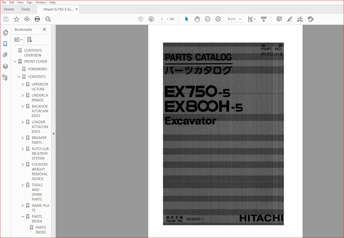
- Hitachi Ex750-5 Ex800H-5 Hydraulic Excavator Parts Catalog
- Hitachi Ex750-5 Ex800H-5 Hydraulic Excavator Technical Operational Principle Manual
- Hitachi Ex750-5 Ex800H-5 Hydraulic Excavator Technical Troubleshooting Manual
- Hitachi Ex750-5 Ex800H-5 Hydraulic Excavator Workshop Manual
Description
Hitachi Ex750-5 Ex800H-5 Excavator Operational Principle+Troubleshooting+Parts+Workshop Manual
FILE DETAILS:
Hitachi Ex750-5 Ex800H-5 Excavator Operational Principle+Troubleshooting+Parts+Workshop Manual
This Listing includes all of the manuals mentioned below:
- Hitachi Ex750-5 Ex800H-5 Equipment Components Parts Catalog
- Hitachi Ex750-5 Ex800H-5 Hydraulic Excavator Electrical Circuit Diagram
- Hitachi Ex750-5 Ex800H-5 Hydraulic Excavator Parts Catalog
- Hitachi Ex750-5 Ex800H-5 Hydraulic Excavator Technical Operational Principle Manual
- Hitachi Ex750-5 Ex800H-5 Hydraulic Excavator Technical Troubleshooting Manual
- Hitachi Ex750-5 Ex800H-5 Hydraulic Excavator Workshop Manual
DESCRIPTION:
Hitachi Ex750-5 Ex800H-5 Excavator Operational Principle+Troubleshooting+Parts+Workshop Manual
INTRODUCTION:
TO THE READER:
• This manual is written for an experienced technician to provide technical information needed to maintain and repair this machine.
• Be sure to thoroughly read this manual for correct product information and service procedures.
• If you have any questions or comments, at if you found any errors regarding the contents of this manual, please contact using “Service Manual Revision Request Form” at the end of this manual.
ADDITIONAL REFERENCES:
• Please refer to the materials listed below in addition to this manual.
• The Operator’s Manual
• The Parts Catalog
• The Engine Manual
• Parts Catalog of the Engine
• Hitachi Training Material
MANUAL COMPOSITION:
• This manual consists of three portions: the Technical Manual (Operational Principle), the Technical Manual (Troubleshooting) and the Workshop Manual.
• Information included in the Technical Manual (Operational Principle): technical information needed for redelivery and delivery, operation and activation of all devices and systems.
• Information included in the Technical Manual (Troubleshooting): technical information needed for operational performance tests, and troubleshooting procedures.
• Information included in the Workshop Manual: technical information needed for maintenance and repair of the machine, tools and devices needed for maintenance and repair, maintenance standards, and removal/installation and assemble/ disassemble procedures.
TABLE OF CONTENTS:
Hitachi Ex750-5 Ex800H-5 Excavator Operational Principle+Troubleshooting+Parts+Workshop Manual
- Hitachi Ex750-5 Ex800H-5 Equipment Components Parts Catalog
PUMP
MOTOR;OIL
VALVE
CYLINDER
PARTS INDEX
- Hitachi Ex750-5 Ex800H-5 Hydraulic Excavator Parts Catalog
UPPERSTRUCTURE
UNDERCARRIAGE
BACKHOE ATTACHMENTS
LOADER ATTACHMENTS
BREAKER PARTS
AUTO-LUBRICATION SYSTEM
COUNTERWEIGHT REMOVAL DEVICE
TOOLS AND SPARE PARTS
NAME-PLATE
PARTS INDEX
- Hitachi Ex750-5 Ex800H-5 Hydraulic Excavator Technical Operational Principle Manual
SECTION 1
GENERAL
Group 1 Specification
SpecificationsT1-1-1
Working Ranges/Transporting
Dimensions T1-1-5
Group 2 Component Specifications
EngineT1-2-1
Engine Accessories T1-2-4
Hydraulic Components T1-2-5
Filters T1-2-7
Electrical Components T1-2-8
Group 3 Component Layout
Main Components T1-3-1
Electrical System (1) T1-3-2
Electrical System (2) T1-3-3
Electrical System (3) T1-3-4
Control ValveT1-3-6
Other Components T1-3-10
SECTION 2
SYSTEM
Group 1 Control System
Outline T2-1-1
Engine Control T2-1-2
Pump Control T2-1-6
Valve ControlT2-1-14
Other Control T2-1-18
Group 2 Hydraulic System
Outline T2-2-1
Main Circuit T2-2-2
Pilot CircuitT2-2-7
Group 3 Electrical System
Outline T2-3-1
Power CircuitT2-3-2
Bulb Check CircuitT2-3-3
Engine Start Circuit T2-3-4
Charging Circuit T2-3-6
Accessory Circuit T2-3-7
Surge Voltage Prevention Circuit T2-3-8
Engine Stop CircuitT2-3-9
SECTION 3
COMPONENT OPERATION
Group 1 Pump Device
Outline T3-1-1
Main PumpT3-1-2
Regulator T3-1-4
Pilot PumpT3-1-12
N Sensor (Engine Speed Sensor) T3-1-12
P Sensor
(Pump Delivery Pressure Sensor)T3-1-12
A Sensor
(Pump Displacement Angle Sensor) T3-1-12
Group 2 Swing Device
Outline T3-2-1
Swing Motor T3-2-2
Valve UnitT3-2-4
Swing Parking Brake T3-2-6
Swing Reduction GearT3-2-7
Group 3 Control Valve
Outline T3-3-1
Hydraulic Circuit T3-3-6
Flow Combiner ValveT3-3-8
Center Bypass Valve T3-3-9
Pump Control ValveT3-3-10
Main Relief ValveT3-3-12
Overload Relief Valve T3-3-13
Make-Up ValveT3-3-13
Holding Valve T3-3-14
Arm Regenerative Valve T3-3-15
Group 4 Pilot Valve
Outline T3-4-1
Operation T3-4-2
Group 5 Travel Device
Outline T3-5-1
Travel Reduction GearT3-5-2
Travel Motor T3-5-3
Travel Brake Valve T3-5-5
Travel Motor Displacement
Angle Shift T3-5-7
Parking BrakeT3-5-9
Group 6 Others (Upperstructure)
Pilot Shut-Off Valve T3-6-1
Shockless Valve T3-6-2
Solenoid ValveT3-6-3
Accumulator T3-6-4
Group 7 Others (Undercarriage)
Swing Bearing T3-7-1
Center JointT3-7-2
Track Adjuster T3-7-3
- Hitachi Ex750-5 Ex800H-5 Hydraulic Excavator Technical Troubleshooting Manual
SECTION 4
OPERATIONAL
PERFORMANCE TEST
Group 1 Introduction
Operational Performance Tests T4-1-1
Preparation for Performance Test T4-1-2
Group 2 Engine Test
Engine SpeedT4-2-1
Injector and Valve Clearance
Adjustment T4-2-3
Group 3 Excavator Test
Travel SpeedT4-3-1
Track Revolution Speed T4-3-2
Mistrack Check T4-3-3
Travel Parking Function CheckT4-3-4
Swing Speed T4-3-6
Swing Function Drift Check T4-3-7
Swing Motor LeakageT4-3-8
Maximum Swingable Slant AngleT4-3-9
Swing Bearing Play T4-3-10
Hydraulic Cylinder Cycle Time T4-3-12
Dig Function Drift Check T4-3-14
Control Lever Operating Force T4-3-15
Control Lever Stroke T4-3-16
Boom Raise / Swing Combined
Operation Check T4-3-17
Group 4 Component Test
Primary Pilot PressureT4-4-1
Secondary Pilot pressureT4-4-3
Swing Preference Circuit Shift Control
Pressure (MA Pressure) T4-4-4
Main Relief Pressure Shift Control
Pressure (SA Pressure) T4-4-5
Travel Mode Shift Control
Pressure (SB Pressure) T4-4-6
Main Relief Pressure T4-4-8
Overload Relief Valve Set PressureT4-4-12
Main Pump Flow Test T4-4-15
Swing Motor Drainage T4-4-20
Travel Motor Drainage T4-4-22
Group 5 Standard
Operational Performance
Standard Table T4-5-1
SECTION 5
TROUBLESHOOTING
Group 1 Diagnosing Procedure
Introduction T5-1-1
Diagnosing Procedure T5-1-2
Dr EX T5-1-4
Dr EX Start Up Procedure T5-1-4
Clearing the Self-Diagnosing
Function T5-1-5
Retrial “A” T5-1-5
Retrial “B” T5-1-6
Fault code ListT5-1-7
Monitoring FunctionT5-1-9
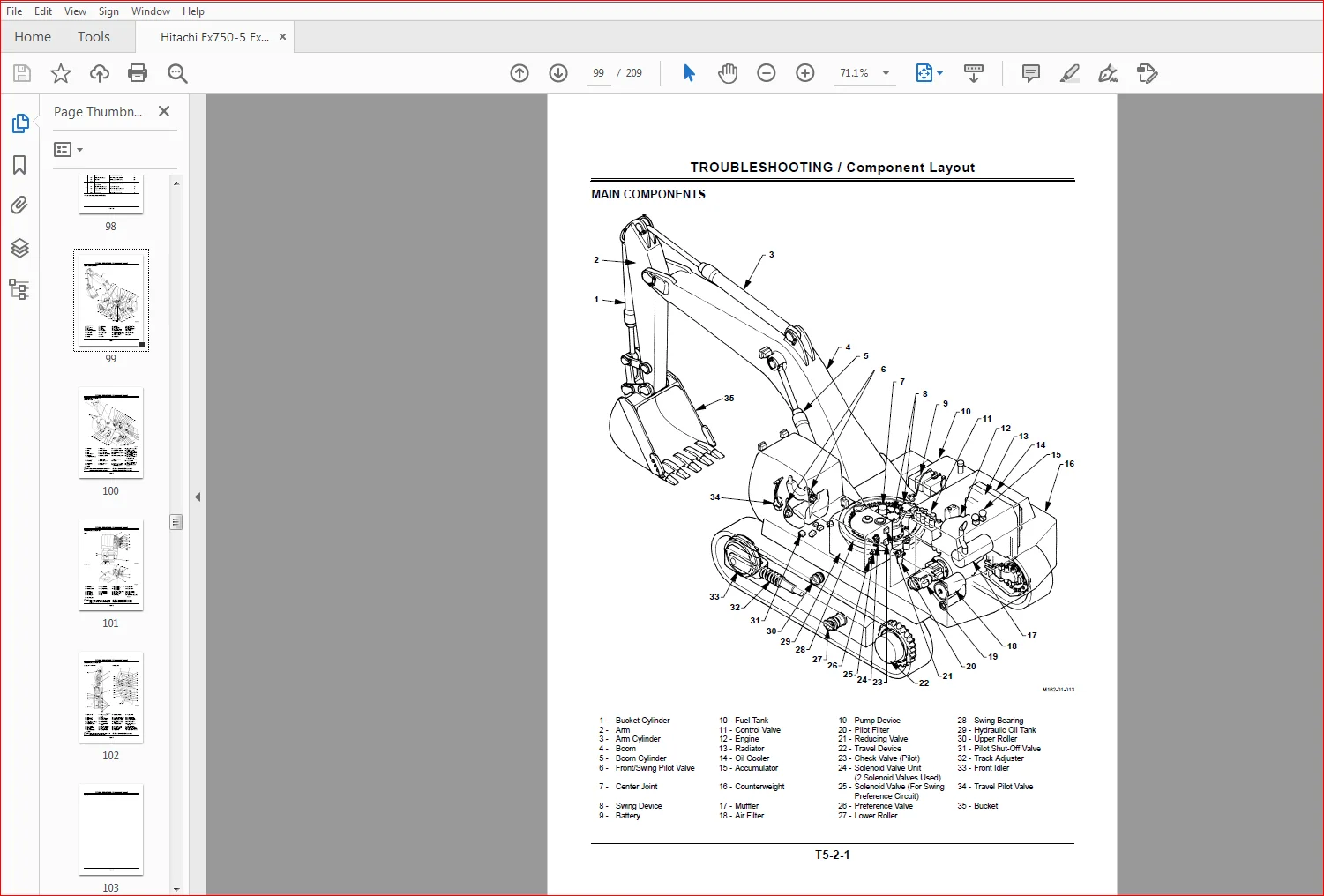
Group 2 Component Layout
Main Components T5-2-1
Electrical System Component (1) T5-2-2
Electrical System Component (2) T5-2-3
Electrical System Component (3) T5-2-4
Control ValveT5-2-6
Others T5-2-10
Group 3 Troubleshooting A
Troubleshooting A Procedure T5-3-1
Fault Code List T5-3-2
Fault Codes 01, 02, 03, 04, 06
(EC Failure) T5-3-4
Fault Code 05 (Communication
Failure between PVC and EC) T5-3-5
Fault Code 09, 10
(EC Sensor Failure) T5-3-6
Fault Code 11, 12 (Engine Control
Dial Failure)T5-3-7
Fault Code 13 (N Sensor Failure) T5-3-8
Fault Code 14, 15 (Overheat Switch L
Failure, Hydraulic Oil Temperature
Sensor Failure) T5-3-9
Fault Codes 17, 18, 19, 21, 22
(PVC Failure)T5-3-10
Fault Code 20 (Communication Failure
between EC and PVC) T5-3-11
Fault Code 23, 24 (Pump Control
Failure) T5-3-12
Fault Code 25, 26, 33, 34
(DP Sensor Failure) T5-3-14
Fault Code 27, 28, 35, 36
(P Sensor Failure) T5-3-15
Fault Code 29, 30, 37, 38
(A Sensor Failure) T5-3-16
Sensor Operating Range ListT5-3-17
Group 4 Troubleshooting B
Troubleshooting B Procedure T5-4-1
Correlation between Part Failure and
Abnormalities that Machine may
Show T5-4-2
Correlation between Troubles and
Part Failures T5-4-6
Engine System Troubleshooting T5-4-10
Total Actuator System
Troubleshooting T5-4-19
Front Attachment System
Troubleshooting T5-4-25
Swing System TroubleshootingT5-4-28
Travel System TroubleshootingT5-4-31
162T-5-2
Troubleshooting for Other
FunctionsT5-4-34
Engine Speed Adjustment T5-4-38
EC Sensor Installation and Voltage
Adjustment T5-4-39
Group 5 Troubleshooting C
Troubleshooting C Procedure T5-5-1
Malfunction of Coolant
Temperature GaugeT5-5-2
Malfunction of Fuel Gauge T5-5-4
Malfunction of Indicator Bulb
Check System T5-5-6
Malfunction of Level
Check SwitchT5-5-6
Malfunction of Engine Oil
Level Indicator T5-5-8
Malfunction of Coolant
Level Indicator T5-5-10
Malfunction of Hydraulic Oil
Level Indicator T5-5-12
Malfunction of Alternator
Indicator T5-5-14
Malfunction of Engine Oil Pressure
Indicator T5-5-15
Malfunction of Overheat Indicator T5-5-16
Malfunction of Fuel Level
Indicator T5-5-17
Malfunction of Air Filter Restriction
Indicator T5-5-18
Malfunction of Hour Meter T5-5-19
Malfunction of Buzzer T5-5-20
Malfunction of Work Light
Indicator T5-5-22
Malfunction of Quick Idle IndicatorT5-5-22
Group 6 Electrical System Inspection
Precautions for Inspection and
MaintenanceT5-6-1
Instructions for Disconnecting
Connectors T5-6-3
Fuse Continuity Test T5-6-4
Fusible Link Inspection and
Replacement T5-6-5
Battery Voltage Check T5-6-5
How to Troubleshoot Alternator
Malfunctions T5-6-6
Continuity Check T5-6-7
Voltage and Current CheckT5-6-8
Relay Replacing Procedure T5-6-12
Group 7 Harness Check
Circuit CheckT5-7-1
- Hitachi Ex750-5 Ex800H-5 Hydraulic Excavator Workshop Manual
SECTION 1
GENERAL IMFORMATION
Group 1 Precautions for Disassembling
and Assembling
Precautions for Disassembling and
Assembling W1-1-1
Maintenance Standard
Terminology W1-1-4
Group 2 Tightening
Tightening Torque Specification W1-2-1
Torque Chart W1-2-2
Piping Joint W1-2-5
SECTION 2
UPPERSTRUCTURE
Group 1 Cab
Remove and Install Cab W2-1-1
Dimensions of the Cab Glass W2-1-7
Group 2 Counterweight
Remove and Install
Counterweight W2-2-1
Group 3 Pump Device
Remove and Install
Pump Device W2-3-1
Disassemble Pump TransmissionW2-3-2
Assemble Pump Transmission W2-3-6
Remove and Install
Main Pump W2-3-9
Disassemble Main PumpW2-3-10
Assemble Main PumpW2-3-16
Maintenance Standard W2-3-20
Disassemble Regulator W2-3-22
Assemble Regulator W2-3-24
Disassemble and Assemble
Pilot PumpW2-3-26
Group 4 Control Valve
Remove and Install
Control Valve W2-4-1
Disassemble
Control Valve 1 W2-4-4
Assemble
Control Valve 1 W2-4-8
Disassemble
Control Valve 2 W2-4-14
Assemble
Control Valve 2 W2-4-16
Disassemble
Control Valve 3 W2-4-18
Assemble
Control Valve 3 W2-4-24
Disassemble
Control Valve 4 W2-4-30
Assemble
Control Valve 4 W2-4-32
Disassemble
Control Valve 5 W2-4-34
Assemble
Control Valve 5 W2-4-36
Group 5 Swing Device
Remove and Install
Swing DeviceW2-5-1
Disassemble Swing Reduction
Gears W2-5-4
Assemble Swing Reduction
Gears W2-5-8
Disassemble Swing Motor W2-5-12
Assemble Swing Motor W2-5-16
Disassemble and Assemble
Swing Parking Brake
Release ValveW2-5-20
Maintenance StandardW2-5-22
SECTION 3
UNDERCARRIAGE
Group 1 Swing Bearing
Remove and Install
Swing Bearing W3-1-1
Disassemble Swing Bearing W3-1-3
Assemble Swing BearingW3-1-5
Group 2 Travel Device
Remove and Install
Travel Device W3-2-1
Disassemble Travel Device W3-2-4
Assemble Travel DeviceW3-2-8
Disassemble Travel Motor W3-2-14
Assemble Travel MotorW3-2-18
Disassemble Brake ValveW3-2-22
Assemble Brake ValveW3-2-24
Maintenance Standard W3-2-26
Group 3 Center Joint
Remove and Install Center JointW3-3-1
Disassemble Center JointW3-3-4
Assemble Center Joint W3-3-6
Maintenance Standard W3-3-8
Group 4 Track Adjuster
Remove and Install
Track Adjuster W3-4-1
Disassemble Track Adjuster W3-4-2
Assemble Track AdjusterW3-4-8
Group 5 Front Idler
Remove and Install Front IdlerW3-5-1
Disassemble Front IdlerW3-5-2
Assemble Front Idler W3-5-6
Maintenance StandardW3-5-8
Group 6 Upper and Lower Roller
Remove and Install
Upper Roller W3-6-1
Remove and Install
Lower Roller W3-6-4
Disassemble Lower Roller W3-6-8
Assemble Lower RollerW3-6-10
Disassemble Lower Roller W3-6-12
Assemble Lower RollerW3-6-14
Maintenance StandardW3-6-12
SECTION 4
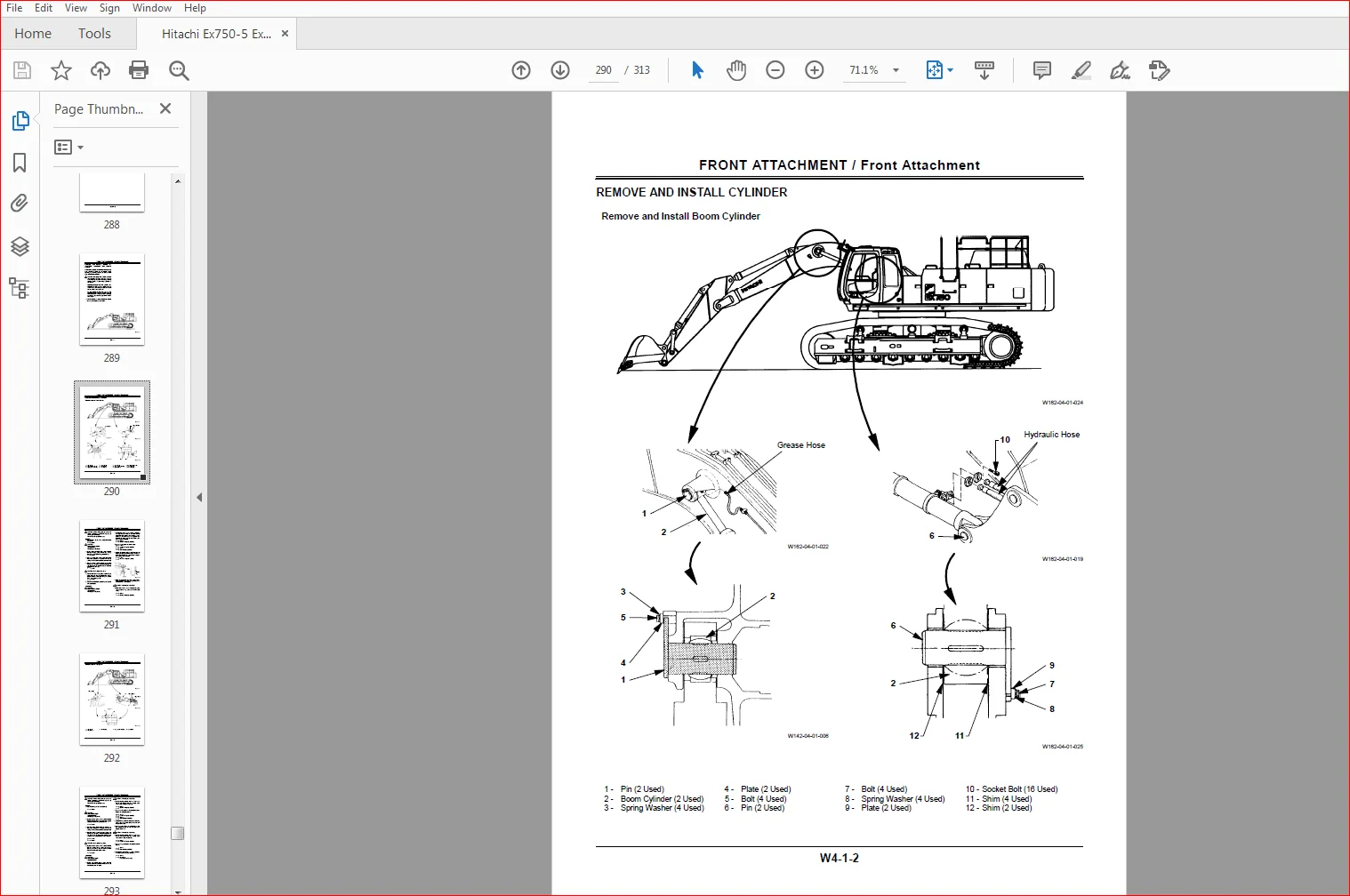
FRONT ATTACHMENT
Group 1 Front????Attachment
Remove and Install Front Attachment
Cylinder and Preparation W4-1-1
Maintenance StandardsW4-1-8
Air Bleeding Procedure W4-1-11
Group 2 Cylinder
Disassemble CylinderW4-2-1
Assemble Cylinder W4-2-6
Maintenance Standard W4-2-10
Group 7 Track
Remove and Install Track W3-7-1
Maintenance StandardW3-7-7
HITACHI EX750-5 EX800H-5 EXCAVATOR OPERATIONAL PRINCIPLE+TROUBLESHOOTING+PARTS+WORKSHOP MANUAL – PDF DOWNLOAD:
IMAGES PREVIEW OF THE MANUAL:
PLEASE NOTE:
- This is the SAME manual used by the dealers to troubleshoot any faults in your vehicle. This can be yours in 2 minutes after the payment is made.
- Contact us at [email protected] should you have any queries before your purchase or that you need any other service / repair / parts operators manual.