Hitachi Hydraulic Excavator UH033 Service Manual – PDF DOWNLOAD
Original price was: $87.00.$31.95Current price is: $31.95.
Hitachi Hydraulic Excavator UH033 Service Manual – PDF DOWNLOAD
Description
Hitachi Hydraulic Excavator UH033 Service Manual – PDF DOWNLOAD
FILE DETAILS:
Hitachi Hydraulic Excavator UH033 Service Manual – PDF DOWNLOAD
Language : English
Pages :603
Downloadable : Yes
File Type : PDF
Size:30.9 MB
IMAGES PREVIEW OF THE MANUAL:
DESCRIPTION
Hitachi Hydraulic Excavator UH033 Service Manual – PDF DOWNLOAD
FOREWORD
- This service manual explains the correct maintenance and repair procedures to ensure optimal performance and maximum service life for Hitachi construction machinery.
- Tne serviceman is requested to read the manual thoroughly and consult it whenever he is not sure of correct servicing. Use the manual not only as a reference guide to maintenance but also a textbook to train new serviceiren who are lillfamiliar with Hitachi construction machinery.
- The manual is divided into four sections such as SPECIFICATIONS, OPERATIONAL PRINCIPLE, DISASSEMBLY and ASSEMBLY and MAINTENANCE STANDARD. A thorough knowledge of the these will help to:
- Diagnose the cause of the failure.
- Determine reuse or replacement of parts.
- 3. Install the units and assemble the parts correctly. We hope that this manual will aid in quick, easy and lower cost servicing of the machines.
TABLE OF CONTENTS:
Hitachi Hydraulic Excavator UH033 Service Manual – PDF DOWNLOAD
UH033 SERVICE MANUAL………………………………………………… 1
CARE OF THE HANDLING…………………………………………….. 1
FOWORD…………………………………………………………. 2
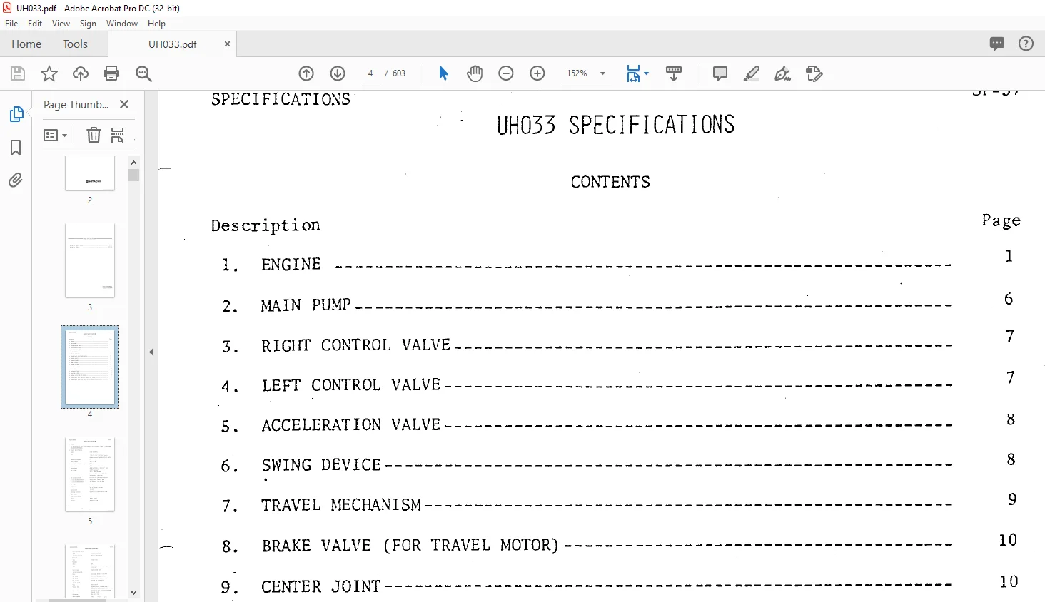
SECTION 01 SPECIFICATIONS………………………………………… 3
Group 01 Specifications (S/N 03001-0550)……………………….. 4
Engine …………………………………………………. 5
Main Pump ………………………………………………. 10
Right Cntrol Valve ………………………………………. 11
Left Cntrol Valve ……………………………………….. 11
Acceleration Valve……………………………………….. 12
Swing Device…………………………………………….. 12
Travel Machanism…………………………………………. 13
Brake Valve……………………………………………… 14
Center Joint…………………………………………….. 14
Boom Cylinder……………………………………………. 14
Arm Cylinder…………………………………………….. 15
Bucket Cylinder………………………………………….. 15
Full-Flow Filter…………………………………………. 16
Oil Cooler………………………………………………. 16
Hydraulic Tank…………………………………………… 16
Suction Filter…………………………………………… 16
Bypass Valve(For Oil Cooler)………………………………. 17
Check Valve(ACC.Valve LOC/VIL)…………………………….. 17
Check valve(Flow Into)……………………………………. 17
Group 02 Specifications (S/N 0551-)……………………………. 18
Engine …………………………………………………. 19
Main Pump……………………………………………….. 24
Pilot Pump………………………………………………. 25
Left Control Valve……………………………………….. 25
Right Control Valve………………………………………. 26
Pilot Valve……………………………………………… 26
Swing Device…………………………………………….. 27
Travel Device……………………………………………. 28
Brake Valve……………………………………………… 28
Center Joint…………………………………………….. 28
Boom Cylinder……………………………………………. 29
Arm Cylinder…………………………………………….. 29
Bucket Cylinder………………………………………….. 29
Oil Cooler………………………………………………. 29
Relief Valve (Bypass Valve)……………………………….. 30
Hydraulic Oil Tank……………………………………….. 30
Foll-Flow Filter…………………………………………. 30
Suction Filter…………………………………………… 30
Offset Boom Front………………………………………… 31
Short Reach Front………………………………………… 32
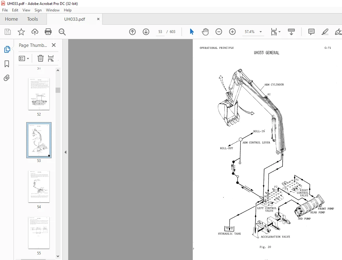
SECTION 02 OPERATIONAL PRINCIPLE………………………………….. 35
Group 01 General(S/N 03001-0550)………………………………. 36
Hydraulic System…………………………………………. 0
Superstructure…………………………………………… 0
Undercarriage……………………………………………. 0
Electric System………………………………………….. 0
Group 02 General(S/N 05001-…………………………………… 83
Hydraulic System…………………………………………. 84
Construction…………………………………………. 84
Hydraulic Circuit…………………………………….. 85
Main Haydraulic Circuit……………………………. 89
Pilot Circuit…………………………………….. 91
Signal Operation……………………………………… 93
Boom Operation……………………………………. 93
Arm Operation…………………………………….. 97
Bucket Operaton……………………………………101
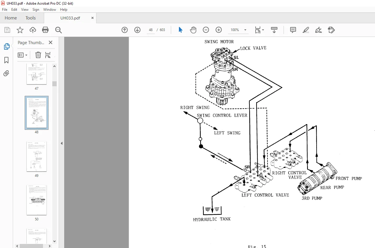
Swing Operation……………………………………103
Travel Operation…………………………………..107
Overload Relief Valve Function………………………113
Combined Operation…………………………………….114
Swing And Travel Operation………………………….115
Arm And Travel Operation……………………………116
Boom And Travel Operation…………………………..117
Swing And Arm Operation…………………………….118
Superstructure……………………………………………119
Outline………………………………………………119
Control Levers………………………………………..120
Undercarriage…………………………………………….125
Outline………………………………………………125
Track Spring And Adjuster………………………………126
Swing Bearing…………………………………………128
Group 03 HVBC 04 Brake Valve…………………………………..130
Group 04 KVM-70 Control Valve………………………………….138
Group 05 MH-04U Control Valve………………………………….151
Group 06 KVM-80 Control Valve………………………………….158
Group 07 Cylinder…………………………………………….171
Group 08 Full-Flow Filter……………………………………..174
Group 09 HNFC Motor…………………………………………..177
Group 10 MSF-140 Swing Motor…………………………………..181
Group 11 PHS 3029-3024 Jagr Pump……………………………….189
Group 12 A10V Axial Pump………………………………………192
Group 13 Monitor Troubleshooting ………………………………211
Introduction……………………………………………..212
Meter(s) Does Not Work…………………………………….214
Maloperation Of Hourneter………………………………….214
Maloperation Of Water Temperature Gauge……………………..215
Accuracy Check Of Water Temperature Gauge……………………216
Maloperation Of Fuel Gauge…………………………………217
Accuracy Check Of Fuel Gate………………………………..218
Monitor Lamp……………………………………………..219
Maloperation Of Battery Charge Warning Lamp………………….220
Maloperation Of Engine Oil Pressure Warning Lamp……………..221
Maloperation Of Engine Overheat Warning Lamp…………………222
Maloperation Of Air Cleaner Clog Warning Lamp……………….223
Maloperation Of Headlight Pilot Lamp………………………..224
Buzzer 1…………………………………………………225
Buzzer 2…………………………………………………226
UHO Circuit Diagram……………………………………….227
SECTION 03 DISASSEMBLY AND ASSEMBLY………………………………..229
Group 01 Air Conditioner………………………………………230
Group 02 HVBC 04 Brake Valve…………………………………..262
Group 03 VLCR-06SG-S Valve Unit………………………………..274
Necessary Tools…………………………………………..275
Disassembling Instructions…………………………………276
Maintenance Standard………………………………………279
Assembling Instruction…………………………………….281
Valve Performance…………………………………………284
Trouble Shooting………………………………………….285
Group 04 KVM-70 Control Valve………………………………….292
Disassembly………………………………………………293
Inspection……………………………………………….296
Assembly…………………………………………………297
Handing Procedures Of Relief Valve………………………….301
Trouble Shooting………………………………………….304
Group 05 MH-04U Control Valve………………………………….308
General Notice On Disassembly And Assembly…………………..309
Necessary Tools…………………………………………..309
Disassembling Instruction………………………………….310
Assembling Instruction…………………………………….314
Adjustment Of Pressure…………………………………….317
Trouble Shooting………………………………………….318
Group 06 KVM-80 ControlValve…………………………………..322
Disassembly………………………………………………323
Inspection……………………………………………….328
Assembly…………………………………………………329
Relief Valve……………………………………………..332
Trouble Shooting………………………………………….334
Group 07 Cylinder…………………………………………….338
Group 08 Front Idler………………………………………….346
Group 09 HMFC Motor…………………………………………..352
Group 10 MSF-140 Swing Motor…………………………………..369
Disassembly………………………………………………371
Maintenance Standerd………………………………………374
Assembly…………………………………………………375
Trouble Shooting………………………………………….379
Group 11 PH-Type Gear Pump…………………………………….384
Group 12 A10V Axial Pump………………………………………392
Group 13 Lower Roller…………………………………………414
Group 14 RGS-140-6 Reduction Device…………………………….419
Group 15 140-G-V Swing Device………………………………….428
Group 16 Traction Device………………………………………433
Group 17 Upper Roller…………………………………………452
SECTION 04 MAINTENANCE STANDERD……………………………………458
Selia1 NO.03001~ 05500………………………………………..459
Genelal………………………………………………….461
1.BASIC MACHINE…………………………………………..463
1.Check of Amount of Oil……………………………….463
1-1 Engine oil…………………………………….463
1-2 Hydraulic oil………………………………….463
1-3 Lube oil………………………………………464
2. Travel Performance Standard………………………….465
2-1 Travel speed ………………………………….465
2-2 Rotating speed of track links……………………466
2-3 Straight running ability in traveling…………….467
2-4 Slippage ,of travel motor in traveling on slope……468
3. Swing Performance Standard…………………………..470
3-1 Swing speed……………………………………470
3-2 Coasting at a time of swing stop…………………471
3-3 Leakage in swing motor on slope………………….472
4. Performance Standard of Front-end Attachments………….473
4-1 Operating time of hydraulic cylinders…………….473
4-2 Gravity retraction of hydraulic cylinders…………475
5. Performance Standard of Control Levers………………..476
5-1 Control lever operating forces…………………..476
5-2 Control lever strokes…………………………..478
2 , HYDRAULIC COMPONENTS…………………………………..481
1. Press’ure Measurements………………………………481
1-1 Main relief valve set pressure…………………..481
1-2 Overload relief valve set pressure……………….481
1-3 Acceleration valve relief valve set pressure………485
1-4 Swing relief valve set pressure………………….486
1-5 Travel brake valve relief set pressure……………487
2. Performance Standard of Pumps………………………..489
2-1 1st & 2nd gear pumps……………………………489
2-2 3rd gear pump………………………………….492
3. Performance Standard of Motors……………………….495
3-1 Quantity of drain of travel motor………………..495
3-2 Quantity of drain of swing motor…………………497
3, MEASURING INSTRUMENTS…………………………………..499
1. List of Measuring Instruments………………………..499
2. External Views of Measuring Instruments……………….500
4, MAINTENANCE STANDARD……………………………………502
1. Swing Bearing………………………………………502
2. Sprocket…………………………………………..503
3. Front Idler………………………………………..504
3-1 Idler…………………………………………504
3- 2 Axle and bushing………………………………504
4. Track Link Tension Adjustment……………………………505
5. Lower Roller & Upper Roller……………………………..507
5-1 Lo Ter roller……………………………………..507
5-1-1 Roller………………………………………507
5-1-2 Axle and bushing……………………………..507
5-2 Upper roller………………………………………508
5-2-1 Roller………………………………………508
5-2-2 Axle and bushing……………………………..508
6. Track Link…………………………………………….509
6-1 Link……………………………………………..509
6-2 Track pin…………………………………………509
6-3 Track pin…………………………………………509
6-4 Master pin………………………………………..510
6-5 Track bushing……………………………………..510
6-6 Master bushing…………………………………….510
6-7 Grouser shoe………………………………………511
6-8 Flat shoe…………………………………………512
6- 9 Triangular shoe…………………………………..512
SeliaI No.05501~……………………………………………..513
BASIC MACHINE PERFORMANCE………………………………….514
1. CHECK OF AMOUNT OF OIL………………………………514
1-1. Engine oil……………………………………514
1-2. Hydraulic oil…………………………………514
1-3. Lube oil……………………………………..515
2. TRAVEL PERFORMANCE STANDARD………………………….516
2-1. Travel speed………………………………….516
2-2. Rotating speed of track links…………………..517
2-3. Straight running ability in traveling……………518
2-4. Slippage of travel motor in traveling on slope……519
3. SWING PERFORMANCE STANDARD…………………………..521
1. Swing speed…………………………………….521
2. Coasting at a time of swing stop………………….522
3. teakage in swing motor on slope…………………..523
4. PERFORMANCE STANDARD OF FRONT-END ATTACHMENTS………….524
1. Operating time of hydraulic cylinder ……………..524
2, Gravity retraction of hydraulic cylinder…………..526
5. PERFORMANCE STANDARD OF CONTROL LEVERS………………..527
1. Control lever operating forces……………………527
2. Control lever strokes……………………………529
HYDRAULIC UNIT PERFORMANCE…………………………………531
PRESSURE MEASUREMENT…………………………………..531
1. Main relief valve……………………………….531
2. Overload relief valve……………………………534
3. Travel motor brake valve…………………………535
4. Swing motor relief valve…………………………536
FD3304 ENGINE……………………………………………………….542
Forword…………………………………………………………543
Tabel Contents…………………………………………………..543
Specification……………………………………………………548
Introduction…………………………………………………544
Engine Specification………………………………………548
Service Procedures……………………………………………550
Engine Adjustment…………………………………………550
Injection timing inspection and adjustment………………550
Compression pressure inspection (including air bleeding)….551
Valve clearance adjustment……………………………..552
Air heater system inspection……………………………553
Servicing Mounted Engine…………………………………..554
Intake duct assembly and intake manifold assembly………..554
Exhaust manifold………………………………………556
Injection pump assembly………………………………..557
Cylinder head assembly…………………………………559
Oil pump assembly and oil cooler assembly……………….573
Overhauling Engine………………………………………..576
Overhauling precautions………………………………..576
Cylinder block assembly………………………………..577
SERVICE DATA…………………………………………………….590
Tightening Torque For Major Engine Parts……………………….590
Engine maintenance Standards…………………………………..592
Periodic Replacement Parts…………………………………….595
Special Tools………………………………………………..596
TROUBLE DIAGNOSIS………………………………………………..599
Trouble Diagnosis By Symptom…………………………………..599
Contact us: [email protected]
PLEASE NOTE:
- This is the SAME manual used by the dealers to troubleshoot any faults in your vehicle. This can be yours in 2 minutes after the payment is made.
- Contact us at [email protected] should you have any queries before your purchase or that you need any other service / repair / parts operators manual.
S.M