Hitachi Hydraulic Excavator Zaxis 160LC-3, 180LC-3, 180LCN-3 Workshop Service Manual – PDF DOWNLOAD
Original price was: $48.95.$21.95Current price is: $21.95.
Hitachi Hydraulic Excavator Zaxis 160LC-3, 180LC-3, 180LCN-3 Workshop Service Manual
Description
Hitachi Hydraulic Excavator Zaxis 160LC-3, 180LC-3, 180LCN-3 Workshop Service Manual
FILE DETAILS:
LANGUAGE:ENGLISH
PAGES:1030
DOWNLOADABLE:YES
FILE TYPE:PDF
HITACHI HYDRAULIC EXCAVATOR ZAXIS 160LC-3, 180LC-3, 180LCN-3 WORKSHOP SERVICE MANUAL – PDF DOWNLOAD:
IMAGES PREVIEW OF THE MANUAL:
DESCRIPTION:
Hitachi Hydraulic Excavator Zaxis 160LC-3, 180LC-3, 180LCN-3 Workshop Service Manual
TO THE READER
• This manual is written for an experienced technician to provide technical information needed to maintain and repair this machine.
• Be sure to thoroughly read this manual for correct product information and service procedures.
• If you have any questions or comments, at if youfound any errors regarding the contents of this manual, please contact using “Service Manual Revision Request Form” at the end of this manual.
ADDITIONAL REFERENCES
• Please refer to the materials listed below in addition to this manual.
• The Operator’s Manual
• The Parts Catalog
• Operation Manual of the Engine
• Parts Catalog of the Engine
• Hitachi Training Material
MANUAL COMPOSITION
• This manual consists of three portions: the Technical Manual (Operational Principle), the Technical Manual (Troubleshooting) and the Workshop Manual.
• Information included in the Technical Manual (Operational Principle): technical information needed for redelivery and delivery, operation and activation of all devices and systems.
• Information included in the Technical Manual (Troubleshooting): technical information needed for operational performance tests, and troubleshooting procedures.
• Information included in the Workshop Manual: technical information needed for maintenance and repair of the machine, tools and devices needed for maintenance and repair, maintenance
standards, and removal/installation and assemble/ disassemble procedures.
TABLE OF CONTENTS:
Hitachi Hydraulic Excavator Zaxis 160LC-3, 180LC-3, 180LCN-3 Workshop Service Manual
Group 1 Specifications
Specifications T1-1-1
Working RangesT1-1-3
Group 2 Component Layout
Main Components T1-2-1
Electrical System (Overview) T1-2-3
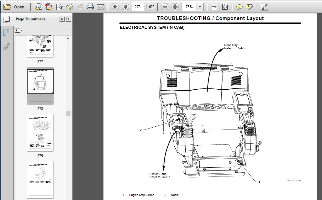
Electrical System (IN CAB)T1-2-4
Electrical System (Rear Tray) T1-2-5
Electrical System (Switch Panel) T1-2-6
Electrical System (Around Air Cleaner) T1-2-7
Electrical System (Relays)T1-2-8
EngineT1-2-9
Pump DeviceT1-2-10
Around Pump DeviceT1-2-10
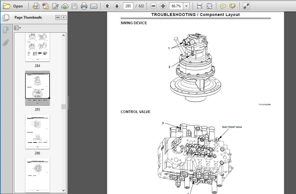
Swing Device T1-2-11
Control ValveT1-2-11
Signal Control Valve T1-2-12
Solenoid Valve Unit T1-2-12
Travel Device T1-2-13
Layout of Attachmet Spec PartsT1-2-14
Group 3 Component Specifications
EngineT1-3-1
Engine Accessories T1-3-4
Hydraulic Component T1-3-5
Electrical Component T1-3-10
Group 1 Controller
Outline T2-1-1
Can (Network Provided for Machine) T2-1-2
MC: Main Controller T2-1-4
ECM: Engine Control Module T2-1-20
ICF: Information Controller T2-1-22
Monitor UnitT2-1-25
Group 2 Control System
Outline T2-2-1
Engine Control T2-2-4
Pump Control T2-2-26
Valve ControlT2-2-42
Other ControlsT2-2-62
Group 3 ECM System
Outline T2-3-1
Fuel Injection Control T2-3-2
Engine Start Control T2-3-10
EGR (Exhaust Gas Recirculation)
Control T2-3-12
Fuel Injection Amount CorrectionT2-3-14
Engine Stop Control T2-3-16
Group 4 Hydraulic System
Outline T2-4-1
Pilot CircuitT2-4-2
Main Circuit T2-4-12
Boom Lower Meter-In Cut Control T2-4-24
Group 5 Electrical System
Outline T2-5-1
Main Circuit T2-5-2
Electric Power Circuit (Key Switch: OFF) T2-5-4
Accessory CircuitT2-5-6
Starting Circuit (Key Switch: START) T2-5-8
Charging Circuit (Key Switch: ON) T2-5-12
Serge Voltage Prevention Circuit T2-5-16
Pilot Shut-Off Circuit (Key Switch: ON) T2-5-18
Security Lock CircuitT2-5-20
Engine Stop Circuit (Key Switch: OFF) T2-5-22
Security Horn CircuitT2-5-24
Working Light Circuit T2-5-26
Wiper Circuit T2-5-28
Group 1 Pump Device
Outline T3-1-1
Main PumpT3-1-2
Regulator T3-1-6
Solenoid ValveT3-1-22
Pilot PumpT3-1-24
Pump Delivery Pressure Sensor T3-1-24
Pump Control Pressure Sensor T3-1-24
Group 2 Swing Device
Outline T3-2-1
Swing Reduction GearT3-2-2
Swing Motor T3-2-3
Swing Parking Brake T3-2-4
Valve UnitT3-2-6
Swing Dampener Valve T3-2-11
Group 3 Control Valve
Outline T3-3-1
Hydraulic Circuit T3-3-18
Flow Combiner ValveT3-3-26
Main Relief ValveT3-3-28
Overload Relief Valve T3-3-30
Regenerative Valve T3-3-32
Anti-Drift Valve T3-3-36
Flow Rate Control Valve T3-3-38
Digging Regenerative ValveT3-3-40
Boom Lower Meter-In Cut Valve T3-3-42
Auxiliary Flow Ccmbiner Valve
and Bypass Shut-Out Valve T3-3-44
Group 4 Pilot Valve
Outline T3-4-1
Operation T3-4-4
Shockless Function
(Only for Travel Pilot Valve) T3-4-12
Group 5 Travel Device
Outline T3-5-1
Travel Reduction GearT3-5-2
Travel Motor T3-5-4
Parking BrakeT3-5-6
Travel Mode Change T3-5-8
Travel Brake Valve T3-5-12
Group 6 Signal Control Valve
Outline T3-6-1
Pilot Port T3-6-2
Shuttle Valve T3-6-6
Shockless Valve T3-6-10
Pump 1 and Pump 2 Flow Rate
Control Valves T3-6-14
Bucket Flow Rate Control Valve Control Spool,
Flow Combiner Valve Control Spool, Swing
Parking Brake Release Spool, Arm 1 Flow Rate
Control Valve Control Spool T3-6-16
Group 5 Component Test
Primary Pilot PressureT4-5-1
Secondary Pilot Pressure T4-5-3
Solenoid Valve Set Pressure T4-5-5
Main Pump Delivery Pressure T4-5-8
Main Relief Valve Set Pressure T4-5-9
Relief Pressure
(When relieving Swing) T4-5-13
Overload Relief Valve Set PressureT4-5-15
Main Pump Flow Rate Measurement T4-5-18
Swing Motor Drainage T4-5-26
Travel Motor DrainageT4-5-29
Group 6 Adjustment
Adjustment T4-6-1
Attachment Setting T4-6-20
Group 5 Troubleshooting A
Troubleshooting A ProcedureT5-5-1
Fault Code List
MCT5-5-2
ECMT5-5-20
ICFT5-5-44
Controller Hardware Failure
MC Fault Code 11000 to 11002 T5-5-50
MC Fault Code 11003T5-5-51
MC Fault Code 11004T5-5-52
CAN Harness Check T5-5-54
Engine Failure
MC Fault Code 11100T5-5-73
MC Fault Code 11101 T5-5-74
Pump Failure
MC Fault Code 11200 T5-5-75
MC Fault Code 11202T5-5-76
MC Fault Code 11206T5-5-77
MC Fault Code 11208T5-5-78
Pilot Failure
MC Fault Code 11301 T5-5-79
MC Fault Code 11302T5-5-80
MC Fault Code 11303T5-5-81
MC Fault Code 11304T5-5-82
MC Fault Code 11307T5-5-84
Proportional Solenoid Valve Failure
MC Fault Code 11400 T5-5-85
MC Fault Code 11401T5-5-86
MC Fault Code 11402T5-5-87
MC Fault Code 11403T5-5-88
MC Fault Code 11404T5-5-89
MC Fault Code 11405T5-5-90
MC Fault Code 11410
(ZX160-3class Only) T5-5-91
CAN Data Reception Failure
MC Fault Code 11910, 11914, 11920T5-5-92
CAN Harness Check
MC Fault Code 11910, 11914, 11920T5-5-94
MC Fault Code 11911, 11918T5-5-97
CAN Harness Check
MC Fault Code 11911, 11918 T5-5-98
Other Failures
MC Fault Code 11901 T5-5-101
ECM, Sensor System
ECM Fault Codes 100, 102, 105,
108, 110, 157, 172 T5-5-102
ECM Fault Codes
174, 636, 723, 10001 T5-5-103
ECM, External Device System
ECM Fault Codes 651, 652, 653,
654, 655, 656, 1347, 10002T5-5-104
ECM, Fuel System
ECM Fault Codes
157, 633, 1239, 1240 T5-5-105
ECM, Engine Protection
ECM Fault Codes 110, 190T5-5-106
ECM, Engine Protection
ECM Fault Codes 987, 1485 T5-5-107
ECM, Internal Circuit System
ECM Fault Codes 628, 1077, 1079,
1080, 10003, 10004, 10005T5-5-108
ECM Fault Codes 10006, 10007, 10008,
10009, 10010, 10011, 10013 T5-5-109
ECM, Communication System
ECM Fault Codes 639 T5-5-110
ICF, Satellite Terminal Fault Codes
14000 to 14003 T5-5-111
ICF, Satellite Terminal Fault Codes
14006, 14008, 14100 to 14106T5-5-115
Monitor Unit Fault Code 13303 T5-5-117
Monitor Unit Fault Code 13304 T5-5-118
Monitor Unit Fault Code 13306, 13308T5-5-119
Monitor Unit Fault Code 13310 T5-5-120
Monitor Unit Fault Code 13311 T5-5-121
Pilot Shut-Off Lever Alarm T5-5-122
PLEASE NOTE:
- This is the same manual used by the dealers to diagnose and troubleshoot your vehicle
- You will be directed to the download page as soon as the purchase is completed. The whole payment and downloading process will take anywhere between 2-5 minutes
- Need any other service / repair / parts manual, please feel free to contact [email protected] . We still have 50,000 manuals unlisted