Hitachi LX15-7 LX20-7 LX30-7 LX40-7 Wheel Loader Shop Manual – PDF DOWNLOAD
Original price was: $65.95.$49.95Current price is: $49.95.
Hitachi LX15-7 LX20-7 LX30-7 LX40-7 Wheel Loader Shop Manual
Description
Hitachi LX15-7 LX20-7 LX30-7 LX40-7 Wheel Loader Shop Manual
FILE DETAILS:
LANGUAGE:ENGLISH
PAGES:653
DOWNLOADABLE:YES
FILE TYPE:PDF
HITACHI LX15-7 LX20-7 LX30-7 LX40-7 WHEEL LOADER SHOP MANUAL – PDF DOWNLOAD:
IMAGES PREVIEW OF THE MANUAL:
DESCRIPTION:
Hitachi LX15-7 LX20-7 LX30-7 LX40-7 Wheel Loader Shop Manual
To Readers of This Manual
This manual provides service staff who have completed basic training with technical information necessary for service activity. For obtaining satisfaction and trust from customers, you are expected to read through this manual and acquire correct product knowledge and service technique.
Reference Material
This manual does not, in principle, describe basic items and overlapped areas with other materials (below) to eliminate redundancy.
• For basic items, refer to training materials such as “Sales and Technical Material.”
• For handling and inspection procedures, refer to “Instruction Manual.”
• For structure and component parts, refer to “Parts Catalog.”
• For handling, maintenance procedure and parts of the engine, refer to materials issued by the engine manufacturer.
Organization
This manual is organized into four parts: 1. General Instructions 2. Construction and Function 3. Oveahaul 4. Troubleshooting
1. General Instructions
Safety during maintenance work and general cautionary instructions are compiled.
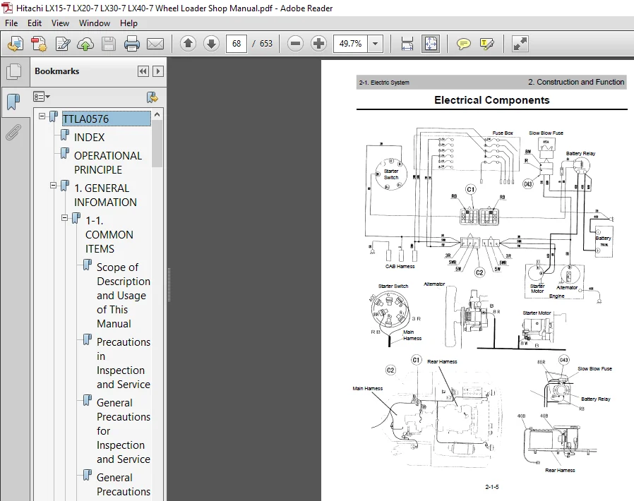
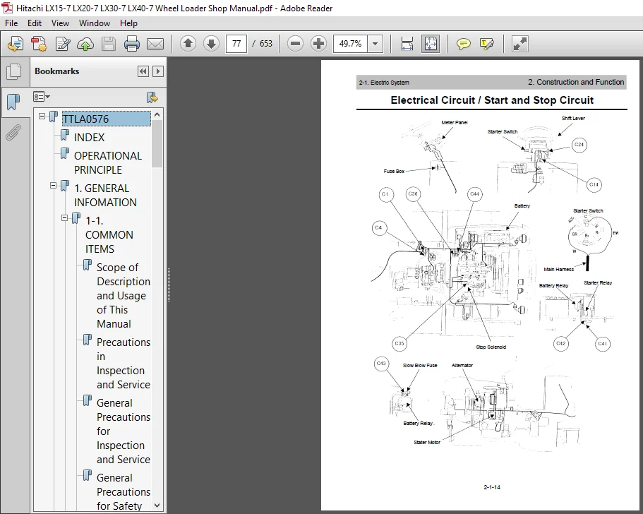
2. Construction and Function
An explanation of the construction and function and an explanation of operation (function) by illustrations, circuit diagrams and system diagrams are compiled.
3. Oveahaul
Methods of removing hydraulic equipment from a vehicle, its disassembly and reassembly, its adjusting method, standard values used for service work and service limits are compiled.
4. Troubleshooting
Probable causes and corrections for troubles are compiled
TABLE OF CONTENTS:
Hitachi LX15-7 LX20-7 LX30-7 LX40-7 Wheel Loader Shop Manual
TTLA0576.................................................................  1
	INDEX................................................................  1
	OPERATIONAL PRINCIPLE................................................  1
	1. GENERAL INFOMATION................................................  2
		1-1. COMMON ITEMS................................................  4
			Scope of Description and Usage of This Manual................  6
			Precautions in Inspection and Service........................  9
			General Precautions for Inspection and Service............... 11
			General Precautions for Safety Operation..................... 12
			Disassembly and Assembly..................................... 19
		1-2. SPECIFICATIONS.............................................. 28
			Outline Drawings/Specifications.............................. 30
			Fuel, Water and Oil Selection and Capacities................. 34
			Weight of Main Components.................................... 38
			Check and Service List....................................... 39
	2. CONSTRUCTION AND FUNCTION......................................... 42
		2-0. ENGINE...................................................... 44
			Engine....................................................... 46
			Engine Assembly, Engine Mount................................ 50
			Air Cleaner.................................................. 51
			Muffler...................................................... 52
			Radiator..................................................... 55
			Engine Control............................................... 57
			Fuel System.................................................. 58
		2-1. ELECTRIC SYSTEM............................................. 62
			Meter Panel.................................................. 64
			Electrical Components........................................ 65
			Electrical Circuit........................................... 69
				Monitor Lamp Circuit..................................... 69
				Gauge Circuit............................................ 71
				Charging Circuit......................................... 73
				Pre-heating Circuit...................................... 74
				Start and Stop Circuit................................... 76
				Traveling System Circuit................................. 78
				Light Circuit............................................ 84
				Horn Circuit............................................. 86
				Auto-leveler Circuit..................................... 87
		2-2. POWER TRAIN I............................................... 88
			Power Train.................................................. 90
			HST.......................................................... 93
			HST Pump..................................................... 94
			HST Motor....................................................107
			HST Piping...................................................113
			HST Oil Filter...............................................114
			Relief Valve.................................................115
			HST Control..................................................116
			HST Hydraulic Circuit........................................117
			Reduction Gear Box...........................................119
		2-3. POWER TRAIN II..............................................122
			Propeller Shaft..............................................124
			Axle.........................................................125
			Differential.................................................128
			Final Gear...................................................130
			Wheel........................................................131
		2-4. BRAKE SYSTEM................................................132
			Brake System.................................................134
			How to Toe...................................................140
			Wet Brake Assembly in Reduction Gear Box.....................141
			Master Cylinder..............................................142
		2-5. STEERING SYSTEM.............................................144
			Steering.....................................................146
			Steering Hydraulic Circuit...................................147
			Power Steering Assembly......................................148
			Steering Cylinder............................................149
		2-6. FRAME.......................................................150
			Frame........................................................152
			Center Pin...................................................153
			Suspension...................................................154
		2-7. HYDRAULIC SYSTEM............................................156
			Main Piping..................................................158
			Control Valve................................................160
			Main Pump....................................................167
			Oil Tank.....................................................168
			Return Filter................................................169
			Lift / Tilt Cylinder.........................................170
		2-8. WORKING EQUIPMENT...........................................172
			Shovel Linkage...............................................174
			Auto-leveler.................................................179
			Shovel Control...............................................180
KM-SM047E-00.............................................................182
	INDEX_SM.............................................................182
	1. GENERAL INFOMATION................................................184
		1-1. Common Items................................................186
			Scope of Description and Usage of This Manual................188
			Precautions in Inspection and Service........................191
			General Precautions for Inspection and Service...............193
			General Precautions for Safety Operation.....................194
			Disassembly and Assembly.....................................201
		1-2. Specifications..............................................210
			Outline Drawings/Specifications..............................212
			Fuel, Water and Oil Selection and Capacities.................216
			Weight of Main Components....................................220
			Check and Service List.......................................221
	2. CONSTRUCTION AND FUNCTION.........................................224
		2-0. Engine......................................................226
			Engine.......................................................228
			Engine Assembly, Engine Mount................................232
			Air Cleaner..................................................233
			Muffler......................................................234
			Radiator.....................................................237
			Engine Control...............................................239
			Fuel System..................................................240
		2-1. Electronic System...........................................244
			Meter Panel..................................................246
			Electrical Components........................................247
			Electrical Circuit...........................................250
				Main Circuit.............................................250
				Monitor Lamp Circuit.....................................251
				Gauge Circuit............................................253
				Charging Circuit.........................................255
				Pre-heating Circuit......................................256
				Start and Stop Circuit...................................258
				Traveling System Circuit.................................260
				Light Circuit............................................266
				Horn Circuit.............................................268
				Auto-leveler Circuit.....................................269
		2-2. Power Train I...............................................270
			Power Train..................................................272
			HST..........................................................275
			HST Pump.....................................................276
			HST Motor....................................................289
			HST Piping...................................................295
			Charging Pump................................................296
			HST Oil Filter...............................................296
			Relief Valve.................................................297
			HST Control..................................................298
			HST Hydraulic Circuit........................................299
			Reduction Gear Box...........................................301
		2-3. Power Train II..............................................304
			Propeller Shaft..............................................306
			Axle.........................................................307
			Differential.................................................310
			Final Gear...................................................312
			Wheel........................................................313
		2-4. Brake System................................................314
			Brake System.................................................316
			How to Toe...................................................322
			Wet Brake Assembly in Reduction Gear Box.....................323
			Master Cylinder..............................................324
		2-5. Steering System.............................................326
			Steering.....................................................328
			Steering Hydraulic Circuit...................................329
			Power Steering Assembly......................................330
			Steering Cylinder............................................331
		2-6. Frame.......................................................332
			Frame........................................................334
			Center Pin...................................................335
			Suspension...................................................336
		2-7. Hydraulic System............................................338
			Main Piping..................................................340
			Control Valve................................................342
			Main Pump....................................................349
			Oil Tank.....................................................350
			Return Filter................................................351
			Lift/Tilt Cylinder...........................................352
		2-8. Working Equipment...........................................354
			Shovel Linkage...............................................356
			Auto-leveler.................................................361
			Shovel Control...............................................362
	3. OVERHAUL..........................................................364
		3-0. Engine......................................................366
			Removal of Engine LX15-7.....................................368
			Installation of Engine LX15-7................................376
			Removal of Engine LX20, 30, 40-7.............................385
			Installation of Engine LX20, 30, 40-7........................393
			Level Check and Addition of Oil in Engine Oil Pan............401
			Adjustment of Engine Control.................................402
			Removal of Radiator LX15-7...................................403
			Installation of Radiator LX15-7..............................406
			Removal of Radiator LX20, 30, 40-7...........................410
			Installation of Radiator LX20, 30, 40-7......................413
			Level Check and Addition of Coolant..........................417
			Removal of Fuel Tank.........................................418
			Installation of Fuel Tank....................................420
			Level Check and Addition of Fuel.............................422
		3-2. Powertrain 1................................................424
			Removal of HST Pump LX15-7...................................426
			Installation of HST Pump LX15-7..............................429
			Removal of HST Pump LX20, 30, 40-7...........................432
			Installation of HST Pump LX20, 30, 40-7......................435
			Disassembly of HST Pump......................................438
			Removal of HST Motor LX15-7..................................440
			Installation of HST Motor LX15-7.............................442
			Removal of HST Motor LX20, 30, 40-7..........................444
			Installation of HST Motor LX20, 30, 40-7.....................446
			Disassembly of HST Motor LX15-7..............................448
			Disassembly of HST Motor LX20, 30, 40-7......................449
			Removal of Reduction Gear....................................450
			Installation of Reduction Gear...............................453
			Reduction Gear Oil Change....................................456
			Level Check and Addition of Fluid in Brake Fluid Tank........457
			Bleeding Brake Fluid Tank....................................458
			Disassembly of Reduction Gear................................459
			Assembly of Reduction Gear...................................465
			Service Standards of Reduction Gear..........................473
		3-3. Powertrain 2................................................474
			Removal of Front Axle........................................476
			Installation of Front Axle...................................478
			Removal of Rear Axle.........................................480
			Installation of Rear Axle....................................482
			Axle Oil Change..............................................485
			Disassembly of Axle..........................................487
			Assembly of Axle.............................................494
			Service Standards of Differential............................506
			Tooth Contact Adjustment of Ring Gear........................507
		3-4. Brake System................................................510
			Removal of Master Cylinder...................................512
			Installation of Master Cylinder..............................514
			Disassembly of Master Cylinder...............................517
			Assembly of Master Cylinder..................................518
			Installation Standards of Brake Control......................519
		3-5. Steering....................................................522
			Removal of Orbit-Roll........................................524
			Installation of Orbit-Roll...................................526
			Disassembly of Orbit-Roll....................................529
			Assembly of Orbit-Roll.......................................534
			Removal of Steering Cylinder.................................540
			Installation of Steering Cylinder............................542
		3-7. Hydraulic System............................................546
			Removal of Control Valve.....................................548
			Installation of Control Valve................................551
			Disassembly of Control Valve.................................555
			Assembly of Control Valve....................................561
			Removal of Main Charging Pump................................569
			Installation of Main Charging Pump...........................571
			Removal of Hydraulic Fluid Tank..............................573
			Installation of Hydraulic Fluid Tank.........................575
			Level Check and Addition of Fluid in Hydraulic Fluid Tank....578
			Disassembly of Cylinder......................................579
			Assembly of Cylinder.........................................582
			Service Standards of Cylinders...............................586
	4. TROUBLESHOOTING / DIAGNOSIS.......................................588
		4-0. Engine......................................................590
		4-2. Powertrain 1................................................596
		4-3. Powertrain 2................................................614
		4-4. Brake System................................................620
		4-5. Steering System.............................................626
		4-7. Hydraulic System............................................630
	SERVICE MANUAL REVISION REQUEST FORM.................................650
WCLA0532.................................................................652
WCLA0533.................................................................653
PLEASE NOTE:
- This is the same manual used by the dealers to diagnose and troubleshoot your vehicle
- You will be directed to the download page as soon as the purchase is completed. The whole payment and downloading process will take anywhere between 2-5 minutes
- Need any other service / repair / parts manual, please feel free to contact [email protected] . We still have 50,000 manuals unlisted