Trusted Business
Verified & Licensed
Virus Free Files
100% Safe Downloads
Secure Payment
SSL Protected
Instant Delivery
Available Immediately
Sale!

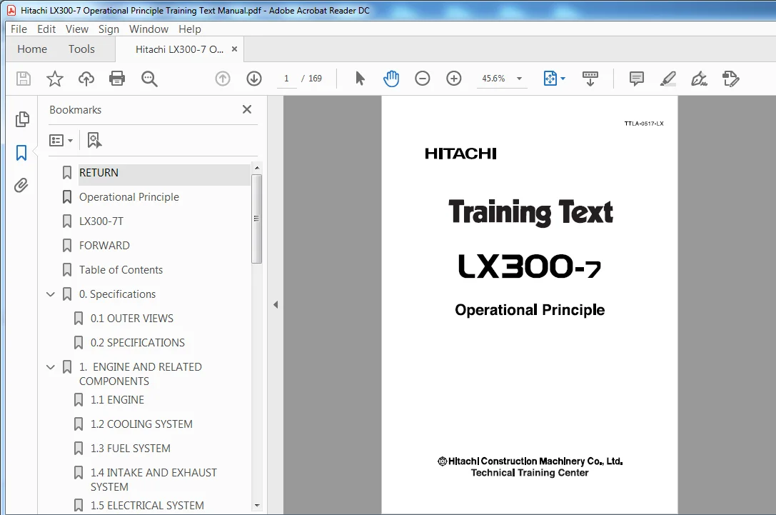
Hitachi LX300-7 Operational Principle Training Text Manual (TTLA-0517-LX) – PDF Download
Original price was: $82.95.$27.95Current price is: $27.95.
- Hitachi LX300-7 Operational Principle Training Text Manual
- Part No:TTLA-0517-LX
Instant PDF Download
Available immediately
Save to Your Device
Download & keep forever
Antivirus Scanned
100% virus-free
Trusted Worldwide
175,000+ customers
Description
Hitachi LX300-7 Operational Principle Training Text Manual (TTLA-0517-LX)
File Details:
Hitachi LX300-7 Operational Principle Training Text Manual (TTLA-0517-LX)
- Manual Language:English
- Pages: 169
- Size: 11.5 MB
- Format:PDF
- Downloadable:Yes
HITACHI LX300-7 OPERATIONAL PRINCIPLE TRAINING TEXT MANUAL (TTLA-0517-LX) – PDF DOWNLOAD:
Image Preview:
Description:
Hitachi LX300-7 Operational Principle Training Text Manual (TTLA-0517-LX)
- Our company offer a wide variety of wheel loaders which have been enthusiastically welcomed by users all over the world. The Model LX300-7 articulated type wheel loader is the latest product developed from years of research and experience. To get the most of the loader, it is required that you become familiar with its features, construction, operating and maintenance procedures.
- This Service Manual explains the structure of the above loaders for service personnel and shop workers. We hope it will be your reference guide during servicing jobs.
- The descriptions and specifications described in this manual are subject to change without notice.
Table Of Contents:
Hitachi LX300-7 Operational Principle Training Text Manual (TTLA-0517-LX)
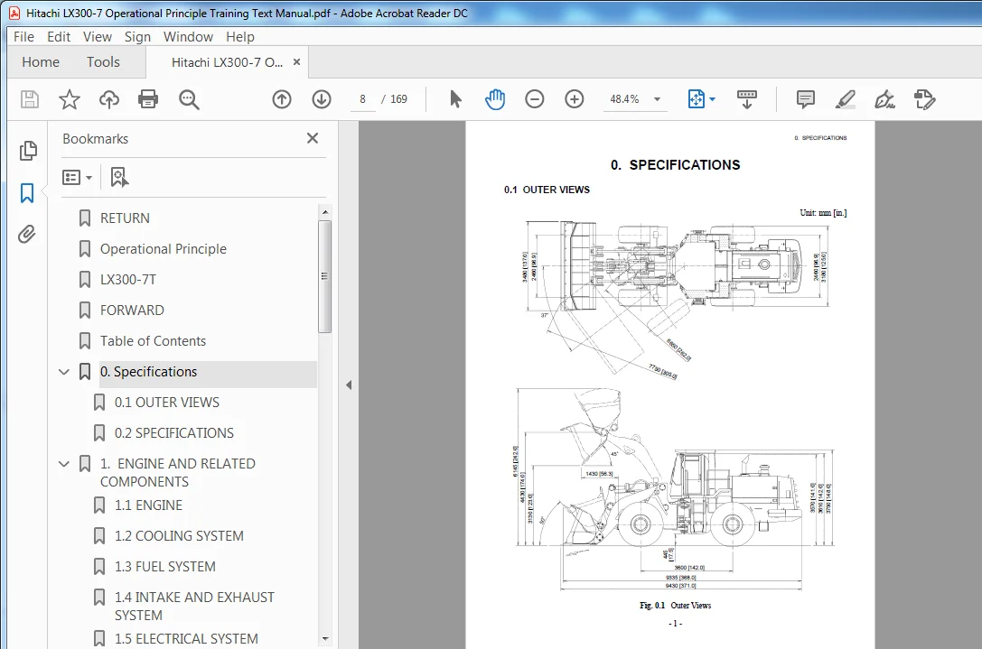
RETURN........................................................  0
Operational Principle.........................................  1
LX300-7T......................................................  2
FORWARD.......................................................  2
Table of Contents.............................................  4
0. Specifications.............................................  8
	0.1 OUTER VIEWS...........................................  8
	0.2 SPECIFICATIONS........................................  9
1.  ENGINE AND RELATED COMPONENTS............................. 12
	1.1 ENGINE................................................ 12
	1.2 COOLING SYSTEM........................................ 17
	1.3 FUEL SYSTEM........................................... 19
	1.4 INTAKE AND EXHAUST SYSTEM............................. 21
	1.5 ELECTRICAL SYSTEM..................................... 25
	1.6 ENGINE CONTROL UNIT................................... 27
2.  POWER TRAIN............................................... 30
	2.1 TORQUE CONVERTER & TRANSMISSION....................... 31
		2.1.1 Torque Converter................................ 34
		2.1.2 Transmission.................................... 36
		2.1.3 Transmission Valve.............................. 41
		2.1.4 Transfer........................................ 61
		2.1.5 Transmission Control............................ 62
		2.1.6 ATC (Autmatic Transmission Controller).......... 67
	2.2 TRANSMISSION OIL CIRCULATION ROUTE.................... 70
	2.3 PROPELLER SHAFTS...................................... 73
	2.4 DAMPER................................................ 74
	2.5 DRIVE AXLES (FRONT AND REAR).......................... 76
		2.5.1 Drive Axle...................................... 76
		2.5.2 Differential.................................... 81
		2.5.3 Final Reduction Grar and Brake Unit............. 84
	2.6 WHEEL ASSEMBLY (TIRE AND WHEEL)....................... 85
		2.6.1 Tire............................................ 85
		2.6.2 Wheel........................................... 86
3.  BRAKE SYSTEM.............................................. 88
	3.1 SERVICE BRAKE......................................... 89
		3.1.1 General Description (Brake Line)................ 89
		3.1.2 Brake Valve..................................... 95
		3.1.3 Charging Valve.................................. 97
		3.1.4 Slack Adjuster.................................. 99
		3.1.5 Disk Brake......................................100
		3.1.6 Other Components................................101
	3.2 PARKING BRAKE.........................................102
		3.2.1 General Description (Brake Line)................102
		3.2.2 Parking Brake Valve.............................104
		3.2.3 Spring Brake Unit...............................105
		3.2.4 Parking Brake Brake.............................106
4.  STEERING SYSTEM...........................................110
	4.1 GENERAL DESCRIPTION...................................110
	4.2 OIL CIRCULATION ROUTES................................112
	4.3 STEERING WHEEL UNIT...................................113
	4.4 STEERING VALVE........................................116
	4.5 CONTROL LINKAGE.......................................119
	4.6 STEERING CYLINDER.....................................120
5.  FRAME AND COCKPIT.........................................122
	5.1 FRAME.................................................122
	5.2 CENTER HINGE PIN......................................124
6.  HYDRAULIC SYSTEM..........................................126
	6.1 OIL CIRCULATION ROUTES (HYDRAULIC CIRCUIT DIAGRAM)....126
	6.2 PUMP..................................................129
		6.2.1 Main Pump.......................................130
		6.2.2 Steering Pump...................................133
		6.2.3 POC & Brake Pump................................135
	6.3 VALVE.................................................136
		6.3.1 Main Valve......................................136
		6.3.2 Pilot Valve.....................................139
	6.4 VALVE CONTROLS........................................140
		6.4.1 System in Operation.............................140
		6.4.2 Stop Valve......................................142
	6.5 OIL TANK..............................................143
7.  LOAD HANDLING SYSTEM......................................145
	7.1 BOOM, BELLCRANK AND BUCKET............................146
		7.1.1 General description.............................146
		7.1.2 Bucket..........................................148
		7.1.3 Bucket Leveler, Boom Kickout and GSS............149
	7.2 CYLINDER..............................................153
		7.2.1 Boom Cylinder...................................153
		7.2.2 Bucket Cylinder.................................153
8.  ELECTRIC SYSTEM...........................................157
	8.1 LIGHTING EQUIPMENT....................................157
	8.2 METERS AND SWITCHES...................................158
		8.2.1 Monitor Lamps (Clusher Gauge Unit)..............158
		8.2.2 Lighting Switch.................................162
		8.2.3 Turn Signal Switch..............................162
	 8.3 ELECTRIC CIRCUIT DIAGRAM.............................163
Please Note:
⦁ This is the SAME manual used by the dealers to troubleshoot any faults in your vehicle. This can be yours in 2 minutes after the payment is made.
⦁ Contact us at [email protected] should you have any queries before your purchase or that you need any other service / repair / parts operators manual.