Hitachi UH07 Hydraulic Excavator Service Repair Workshop Manual PDF
$28.95
Complete factory service manual for Hitachi UH07 hydraulic excavator covering all maintenance, repair, and overhaul procedures. Comprehensive technical documentation includes engine specifications (Isuzu DA640), hydraulic system diagrams, undercarriage service, control valve adjustments, and complete disassembly/assembly instructions. Essential professional guide for servicing 18-ton class mini excavators with detailed diagrams, torque specifications, and troubleshooting procedures.
Description
Hitachi UH07 Hydraulic Excavator Service Repair Workshop Manual Mini Digger PDF DOWNLOAD
DESCRIPTION
This is the complete official Hitachi UH07 Service Manual for the UH07 hydraulic excavator. This comprehensive factory workshop manual provides professional-grade service information for technicians and mechanics servicing this popular compact hydraulic excavator used in construction, demolition, and excavation applications.
Model Covered by This Service Manual
Hitachi UH07 Hydraulic Excavator
- Class: 18-ton compact hydraulic excavator
- Engine: Isuzu DA640 diesel engine
- Type: Crawler-mounted excavator with 360° swing capability
- Applications: General excavation, construction, demolition, material handling
Technical Specifications Summary
Machine Specifications:
Weight:
- With short arm and 0.7 m³ bucket: 18.2t (40,040 lbs)
- With long arm and 0.7 m³ bucket: 18.5t (40,260 lbs)
Dimensions:
- Overall Height: 2,820 mm (9’3″) at cab
- Overall Length of Crawler: 3,904 mm (12’9.7″)
- Track Link Width: 610 mm (24″) standard
- Overall Width: 2,765 mm (9’0.9″) including door handle
- Crawler Width: 2,760 mm (9’0.7″) standard track link
- Ground Pressure: 0.44 kg/cm² (6.25 lbs/in²) standard track link
Performance:
- Swing: Complete 360° continuous rotation
- Swing Speed: 10 rpm
- Traction Speed: 2.6 km/hr (1.62 mph)
- Maximum Gradeability: 58% continuous (30°)
- Cycle Time: 18-25 seconds
Engine:
- Type: Isuzu DA640 diesel engine
- Rated Output: 93 PS at 2,000 rpm
- Configuration: 4-cylinder diesel
Hydraulic System:
- Hydraulic Pump: Piston pump × 2 (dual pump system)
- Swing Motor: Piston motor × 1
- Traction Motors: Piston motor × 2
- System: Dual independent hydraulic circuits (Pump A and Pump B)
Complete Manual Contents (242 Pages)
This Hitachi UH07 service manual PDF is organized into comprehensive chapters covering all major systems:
CHAPTER 1: GENERAL
1.1 General Specifications
- Complete machine specifications
- Weight configurations for different arm/bucket combinations
- Dimensional data with metric and imperial measurements
- Performance parameters
- Ground pressure calculations
- Engine specifications
- Hydraulic system overview
1.2 General Service Data
- Maintenance intervals
- Service capacities
- Lubricant specifications
- Torque specifications
- Standard service procedures
1.3 Engine Performance Curve
- Power output curves
- Torque characteristics
- Fuel consumption data
- Operating range specifications
1.4 Removal and Installation
- Major component removal procedures
- Installation sequences
- Alignment specifications
- Torque requirements
Constructions Overview:
Superstructure Components:
- Steel plate and die steel welded construction
- Swing frame with boom support
- Engine support structure
- Fuel tank mounting
- Hydraulic tank placement
- Operator’s cab assembly
- Hydraulic components layout
- Control devices mounting
- Swing bearing connection to undercarriage
Undercarriage Components:
- Track frame (box-type welded steel plate construction)
- Center joint assembly
- Front idlers
- Propel devices (traction motors and final drives)
- Upper rollers (track rollers)
- Lower rollers (track rollers)
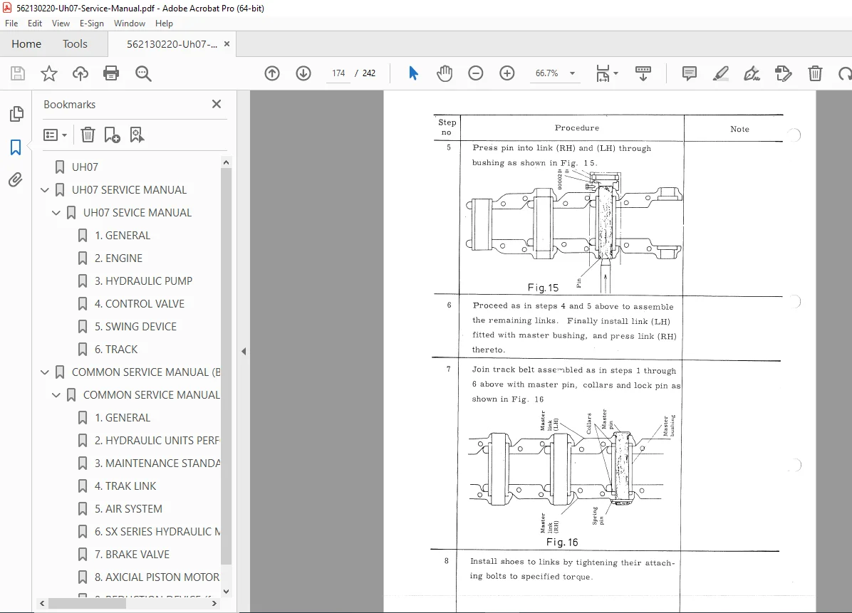
- Track links
- Swing bearing installation on box frame
Front-End Attachments:
Backhoe Attachments:
- Boom assembly
- Arm assembly (short and long arm options)
- Bucket (0.7 m³ standard)
- Boom cylinders (hydraulic actuation)
- Arm cylinder
- Bucket cylinder
- Link A and Link B mechanisms
- Pin connections to superstructure
Clamshell Attachments:
- Boom (identical to backhoe boom)
- Arm (identical to backhoe arm)
- Clamshell bucket assembly
- Specialized hydraulic controls
Hydraulic System Overview:
Dual Independent Pump System:
- Pump A: Supplies right control valve
- Pump B: Supplies left control valve
- Independent power sources for simultaneous operations
Right Control Valve (4 Spools):
- Boom control (2-position: high/low speed)
- Bucket control
- Right propel control
- Reserved spool (plugged, prepared for breaker attachment)
Left Control Valve (4 Spools):
- Left propel control
- Arm control
- Swing control
- Additional function control
Control Lever Configuration: Connected to Right Control Valve:
- Boom lever (dual-speed: standard/high flow)
- Bucket lever
- Right propel control lever
Connected to Left Control Valve: 4. Left propel lever 5. Arm lever 6. Swing lever
Hydraulic Circuit Features:
- Overlapping motion capability
- Quick and firm operation response
- Large capacity main relief valve
- Safety valves for boom, arm, and bucket cylinders
- Full-flow filters
- Oil cooler
- Brake valve for swing motor
- Slow return valve
- Drain filter
- Suction pipe filtering
- Abnormal pressure prevention system
CHAPTER 2: ENGINE
2.1 Specifications
- Isuzu DA640 diesel engine complete specifications
- Displacement and bore/stroke
- Compression ratio
- Valve timing specifications
- Injection timing
- Cooling system specifications
- Lubrication system details
2.2 Principal Operation
- Engine operating principles
- Fuel system operation
- Cooling system flow
- Lubrication system paths
- Air intake system
- Exhaust system
2.3 Adjustment
- Valve clearance adjustment procedures
- Injection timing adjustment
- Idle speed adjustment
- Governor adjustment
- Belt tension specifications
2.4 Removal and Installation
- Complete engine removal procedure
- Installation sequence
- Alignment procedures
- Connection specifications
- Mounting bolt torques
2.5 Disassembly and Assembly
- Cylinder head service
- Piston and connecting rod service
- Crankshaft and bearing service
- Camshaft service
- Timing gear service
- Fuel injection pump service
- Turbocharger service (if equipped)
- Water pump service
- Oil pump service
CHAPTER 3: HYDRAULIC PUMP
3.1 Specifications
- Piston pump specifications (Pump A and Pump B)
- Displacement specifications
- Pressure ratings
- Flow rates
- Mounting specifications
3.2 Principal Operation
- Piston pump operating principles
- Swash plate mechanism
- Pressure compensation
- Flow control
- Load sensing operation
3.3 Adjustment
- Pump pressure adjustment
- Flow adjustment
- Swash plate angle adjustment
- Servo piston adjustment
3.4 Removal and Installation
- Pump removal procedures
- Drive coupling service
- Installation alignment
- Connection torque specifications
- Testing procedures
3.5 Disassembly and Assembly
- Complete pump disassembly sequence
- Internal component inspection
- Wear limit specifications
- Clearance measurements
- Assembly procedures
- Seal replacement
- Testing and verification
CHAPTER 4: CONTROL VALVE
4.1 Specifications
- Right and left control valve specifications
- Spool specifications
- Port sizes and configurations
- Pressure ratings
- Flow characteristics
4.2 Principal Operation
- Spool valve operation
- Center bypass operation
- Pressure relief operation
- Load sensing operation
- Priority valve operation
- Brake valve operation
4.3 Adjustment
- Relief valve pressure adjustment
- Spool positioning adjustment
- Detent adjustment
- Brake valve adjustment
4.4 Removal and Installation
- Control valve removal
- Hydraulic line disconnection
- Control linkage removal
- Installation procedures
- Connection torque specifications
4.5 Disassembly and Assembly
- Valve block disassembly
- Spool removal and inspection
- Spring replacement
- Seal replacement
- Assembly sequence
- Testing procedures
CHAPTER 5: SWING DEVICE
5.1 Specifications
- Swing motor specifications
- Swing bearing specifications
- Swing brake specifications
- Swing reduction gear specifications
5.2 Operational Principle
- Swing motor operation
- Planetary reduction operation
- Brake valve operation
- Swing bearing load distribution
5.3 Disassembly and Assembly
- Swing motor removal
- Swing reduction disassembly
- Bearing inspection
- Seal replacement
- Assembly procedures
- Adjustment specifications
CHAPTER 6: SWING BEARING
6.1 Specifications
- Bearing dimensions
- Load capacity
- Gear specifications
- Mounting bolt specifications
6.2 Service Procedures
- Bearing inspection
- Wear measurement
- Gear backlash adjustment
- Bolt torque specifications
- Lubrication procedures
CHAPTER 7: PROPELLING DEVICE
7.1 Specifications
- Traction motor specifications (2 motors)
- Final drive specifications
- Reduction ratio
- Brake specifications
7.2 Operation
- Traction motor operation
- Final drive reduction
- Automatic brake operation
- Parking brake system
7.3 Service Procedures
- Motor removal and installation
- Final drive disassembly
- Bearing replacement
- Seal replacement
- Brake adjustment
- Oil change procedures
CHAPTER 8: DRIVE TUMBLER (SPROCKET)
8.1 Specifications
- Sprocket specifications
- Tooth profile
- Material specifications
- Mounting specifications
8.2 Service Procedures
- Wear inspection criteria
- Replacement procedures
- Installation alignment
- Bolt torque specifications
CHAPTER 9: FRONT IDLER
9.1 Specifications
- Idler wheel specifications
- Bearing specifications
- Adjustment mechanism
- Mounting specifications
9.2 Service Procedures
- Track tension adjustment
- Idler removal and installation
- Bearing replacement
- Seal replacement
- Grease nipple location
CHAPTER 10: TRACK ROLLER (UPPER AND LOWER ROLLERS)
10.1 Specifications
- Upper roller specifications
- Lower roller specifications
- Bearing specifications
- Seal specifications
10.2 Service Procedures
- Roller inspection criteria
- Bearing replacement
- Seal replacement
- Installation procedures
- Lubrication points
CHAPTER 11: CENTER JOINT
11.1 Specifications
- Center joint specifications
- Seal specifications
- Oil passage specifications
11.2 Service Procedures
- Center joint disassembly
- Seal replacement
- Bearing service
- Oil passage cleaning
- Assembly and testing
Major Component Systems
Hydraulic Cylinders:
- Boom cylinders (2 units)
- Arm cylinder (1 unit)
- Bucket cylinder (1 unit)
- Cylinder specifications
- Seal kits
- Rod and tube inspection
- Piston replacement
- Cylinder testing
Hydraulic Hoses and Fittings:
- Hose routing diagrams
- Hose specifications
- Fitting torque specifications
- Replacement procedures
- Inspection criteria
Electrical System:
- Starting system
- Charging system
- Instrument panel
- Safety switches
- Wiring diagrams
- Troubleshooting procedures
Fuel System:
- Fuel tank capacity
- Fuel filters
- Injection system
- Fuel line routing
- System bleeding
Cooling System:
- Radiator specifications
- Coolant capacity
- Thermostat specifications
- Water pump operation
- Fan operation
Lubrication System:
- Engine oil capacity
- Hydraulic oil capacity
- Gear oil capacities
- Grease points
- Oil filter specifications
- Change intervals
Service and Maintenance Information
Hydraulic Oil:
- Recommended specifications
- Capacity specifications
- Change intervals
- Filter replacement
- Contamination checking
Greasing Points:
- Swing bearing greasing
- Track link greasing
- Pin and bushing lubrication
- Cylinder rod protection
Adjustment Procedures:
- Track tension adjustment
- Control linkage adjustment
- Valve pressure settings
- Engine adjustments
- Brake adjustments
Troubleshooting:
- Hydraulic system problems
- Engine problems
- Electrical problems
- Undercarriage problems
- Operator control problems
- Diagnostic procedures
- Pressure testing procedures
- Flow testing procedures
Detailed Diagrams and Illustrations
Complete Coverage:
- Exploded view diagrams for all major assemblies
- Hydraulic circuit system diagram (comprehensive)
- Dimensional body and frame diagrams
- Component location diagrams
- Cross-sectional views
- Wiring diagrams
- Torque specification charts
- Service tool illustrations
Hydraulic Circuit Details:
- Complete system schematic (Fig. 1-3)
- Pump configuration
- Control valve arrangement
- Cylinder connections
- Motor connections
- Relief valve locations
- Filter positions
- Oil cooler placement
- Tank connections
- Brake valve circuit
- Slow return valve operation
Professional Service Features
Comprehensive Documentation:
- Written by Hitachi Construction Machinery Co., Ltd.
- Same manual used by authorized Hitachi service centers
- Professional technical terminology
- Clear step-by-step procedures
Visual Learning:
- High-resolution photographs
- Detailed line drawings
- Exploded assembly diagrams
- Cross-sectional illustrations
- Component identification callouts
Specification Tables:
- Torque specifications
- Clearance specifications
- Wear limits
- Service capacities
- Adjustment values
Who Should Use This Manual?
This hydraulic excavator repair guide is essential for:
- Professional heavy equipment technicians
- Hitachi authorized service centers
- Independent construction equipment repair shops
- Fleet maintenance departments
- Equipment rental company service teams
- Technical training institutions
- Experienced mechanics with hydraulic excavator knowledge
Required Knowledge:
- Understanding of hydraulic systems and principles
- Diesel engine service experience
- Heavy equipment mechanical aptitude
- Hydraulic pressure testing capability
- Proper use of service tools and equipment
Important Service Notes
Safety Critical Equipment: This is heavy construction equipment requiring:
- Proper lifting equipment for component service
- Hydraulic pressure relief before disassembly
- Proper blocking and support during service
- Qualified technician knowledge
- Adherence to safety procedures
Precision Requirements:
- Hydraulic system cleanliness essential
- Torque specifications must be followed
- Proper adjustment critical for performance
- Genuine Hitachi parts recommended
- Contamination control during service
Environmental Considerations:
- Proper disposal of hydraulic oil
- Engine oil recycling
- Filter disposal procedures
- Coolant handling
- Regulatory compliance
FILE DETAILS
| Attribute | Details |
|---|---|
| Manual Name | Hitachi UH07 Hydraulic Excavator Service Manual |
| Model Covered | UH07 |
| Machine Type | Compact Hydraulic Excavator (18-ton class) |
| Engine | Isuzu DA640 Diesel, 93 PS @ 2,000 rpm |
| Hydraulic System | Dual piston pump, dual control valve |
| Weight | 18.2-18.5 metric tons |
| Bucket Capacity | 0.7 m³ (0.92 yd³) |
| Manual Type | Factory Service & Repair Workshop Manual |
| File Format | PDF (A4 size pages, landscape orientation) |
| File Size | ~14.4 MB |
| Total Pages | 242 pages |
| PDF Quality | High-resolution scanned factory manual |
| Language | English |
| Publisher | Hitachi Construction Machinery Co., Ltd. |
| Document Date | 2006 |