Hitachi UH801 Service Manual – PDF DOWNLOAD
Original price was: $67.00.$28.95Current price is: $28.95.
Hitachi UH801 Service Manual – PDF DOWNLOAD
Description
Hitachi UH801 Service Manual – PDF DOWNLOAD
FILE DETAILS:
Hitachi UH801 Service Manual – PDF DOWNLOAD
Language : English
Pages :425
Downloadable : Yes
File Type : PDF
Size:20.5 MB
DESCRIPTION
Hitachi UH801 Service Manual – PDF DOWNLOAD
FOREWORD
- This service manual explains the correct maintenance and repair procedures to ensure optimal performance and maximum service life for Hitachi construction machinery The serviceman is requested to read the manual thoroughly and consult it whenever he is not sure of correct servicing.
- Use the manual not only as a reference guide to maintenance but also a text book to train new serviceman who are unfamiliar with Hitachi construction machinery.
- The manual is divided into four sections such as SPECIFICATIONS, OPERATIONAL PRINCIPLE and DISASSEMBLY & ASSEMBLY.
A thorough knowledge of the these will help to:
1. Diagnose the cause of the failure.
2. Determine reuse or replacement of parts.
3. Install the units and assemble the parts correctly.
We hope that this manual will ain in quick, easy and lower cost servicing of the machines.
IMAGES PREVIEW OF THE MANUAL:
TABLE OF CONTENTS:
Hitachi UH801 Service Manual – PDF DOWNLOAD
UH801 SARVICE MANUAL…………………………………………. 1
FOREWORD………………………………………………… 1
CARE OF THE HANDLING……………………………………… 2
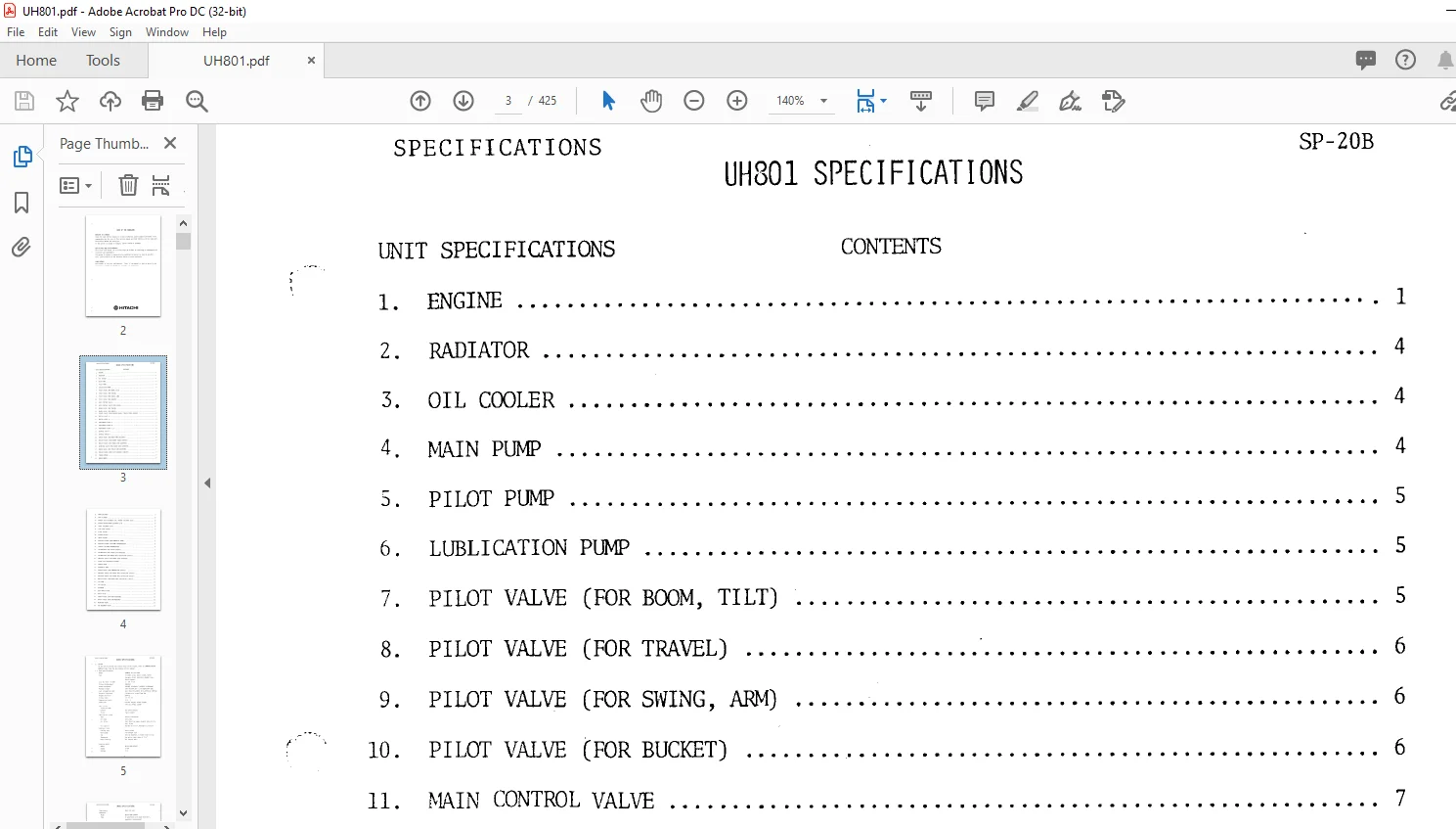
SECTION 01 SPECIFICATIONS…………………………………. 3
Group 01 Specifications……………………………….. 3
Engine…………………………………………… 5
Radiator…………………………………………. 8
Oil Cooler……………………………………….. 8
Main Pump………………………………………… 8
Pilot Pump……………………………………….. 9
Lublication Pump………………………………….. 9
Pilot Valve (For Boom,Tilt)………………………… 9
Plot Valve (For Travel)……………………………. 10
Pilot Valve (For Swing,Arm)………………………… 10
Pilot Valve (For Bucket)…………………………… 10
Main Control Valve………………………………… 11
Main Control Valve (For Swing)……………………… 11
Brake Valve (For Travel)…………………………… 11
Brake Valve(For Swing)…………………………….. 11
Change Valve (For Parking Brake,Travel Speed Change)….. 12
Switch Valve A……………………………………. 12
Switch Valve B……………………………………. 12
Preference Valve A………………………………… 12
Preference Valve B………………………………… 12
Preference Valve C,D………………………………. 12
Shuttle Valve A…………………………………… 12
Shuttle Valve B…………………………………… 12
Check Valve (For Main Pump Delivery)………………… 12
Relief Valve (For Bucket Close Circuit)……………… 12
Relief Valve (For Track Link Adjuster)………………. 12
Reducing Valve (For Track Link Adjuster)…………….. 13
Check Valve (For Track Link Adjuster)……………….. 13
Relief Valve (For Pilot Control Circuit)…………….. 13
Travel Motor……………………………………… 13
Swing Motor………………………………………. 13
Boom Cylinder…………………………………….. 13
Arm Cylinder……………………………………… 14
Bucket Tilt Cylinder (LA),Bucket Cylinder (B/H)………. 14
Bucket Bottom Dump Cylinder (L/D)…………………… 14
Level Cylinder (L/D)………………………………. 14
Full-Flow Filter………………………………….. 14
Pilot Filter……………………………………… 15
Bypass Filter…………………………………….. 15
Drain Filter……………………………………… 15
Suction Filter (For Hydraulic Tank)…………………. 15
Suction Filter (For Pump Trasmission)……………….. 15
Cooler (In Pump Transmission)………………………. 15
Accumulator (For Pilot Circuit)…………………….. 15
Accumulator (For Track Link Adjuster)……………….. 16
Accumulator (For Swing Anti-cavitation Circuit……….. 16
Thorottle valve (For Track Link Adjuster)……………. 16
Track Link Adjuster Cylinder……………………….. 16
Center Joint……………………………………… 16
Hydraulic Tank……………………………………. 16
Change Valve (For Combination Circuit)………………. 16
Throttle Valve (For Swing Anti-Cavitation Circuit)……. 16
Reducing Valve (For Swing Anti-Cavitation Circuit)……. 16
Relief Valve (For Swing Anti-cavitation Circuit)……… 16
Air Tank…………………………………………. 17
Air Filter……………………………………….. 17
Governor…………………………………………. 17
Auto-Drain valve………………………………….. 17
Check valve………………………………………. 17
Safety Valve (For High Pressure)……………………. 17
Safety valve (For Low Pressure)…………………….. 17
Reducing Valve……………………………………. 17
Air Solenoid Valve………………………………… 17
SECTION 02 OPERATION PRINCIPLE…………………………….. 18
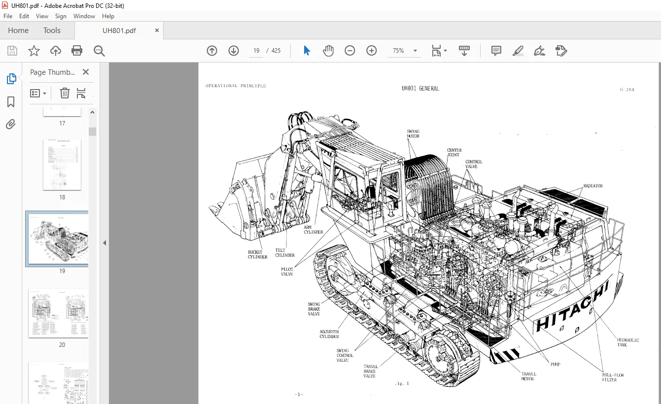
Group 01 UH801 General………………………………… 19
Hydraulic Circuit…………………………………. 19
Pilot Circuit…………………………………. 21
Pilot Pressure Control…………………………. 22
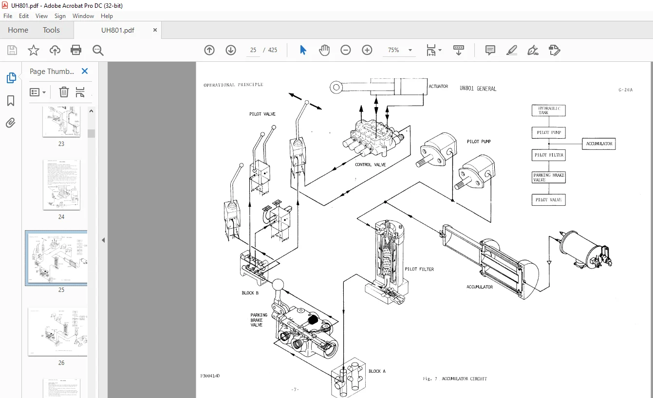
Accumulator Function…………………………… 24
Parking Brake Circuit………………………….. 27
Tarvel Speed Change Circuit…………………….. 31
Pump Suction Circuit…………………………… 35
Main Pump Delivery Circuit……………………… 36
Delivery Preesure Control………………………. 38
Main Pump Displacement Control………………….. 39
Return Circuit ……………………………….. 41
Drain Circuit…………………………………. 45
Loader Front Attachment……………………………. 48
Arm Control Circuit……………………………. 48
Arm Auto Levelling Circuit……………………… 55
Signal Control Circuit…………………………. 58
Swing Anti-Cavitation Circuit…………………… 59
Travel Control Circuit…………………………. 62
Boom Control Circuit…………………………… 66
Bottom Dump Control Circuit…………………….. 83
Backhoe Front Attachment…………………………… 87
Boom Control Circuit…………………………… 87
Arm Control Circuit……………………………. 95
Bucket Control Circuit………………………….103
Main Hydraulic Circuit (Loader)………………….109
Pilot Circuit (Loader)………………………….110
Main Hydraulic Circuit (Backhoe)…………………111
Pilot Circuit (Backhoe)…………………………112
Air Circuit……………………………………….113
General……………………………………….114
Air Compressor…………………………………117
Governor………………………………………118
Air Filte……………………………………..119
Reducing Valve…………………………………120
Auto-Drain Valve……………………………….121
Air Pressure Valve……………………………..122
Air Quick Exhaust Circuit……………………….123
Tracck Link Adjuster……………………………….124
Outline ………………………………………124
Adjuster Cylinder………………………………125
Troubleshooting……………………………………126
Group 02 Accumulator…………………………………..128
Group 03 Air Conditioner……………………………….130
General Circuit……………………………………130
Operation…………………………………………131
Cooling Operation………………………………131
Handling………………………………………131
Heating Operation………………………………131
Air Conditioning Operation………………………131
Function………………………………………….132
Baisic Operating Principles……………………..132
Refrigeration Cycle…………………………….134
Functions Of Compressor…………………………135
Automatic Temperature-Controlling Expansion Valve….139
Evaporator…………………………………….141
Condenser……………………………………..143
Liquid Tank……………………………………144
Thermostat…………………………………….147
Group 04 B63C Brake Valve………………………………148
Group 05 Check Valve…………………………………..155
Group 06 MVPH Control Valve…………………………….156
Outline…………………………………………..156
Spool End Chamber………………………………….156
Spool Movement…………………………………….157
Open-Center Spool (M Type)………………………….160
Close-Center Spool (D Type)…………………………161
Main Relief Valve…………………………………162
Overload Relief Valve………………………………165
Group 07 SX Motor……………………………………..170
Group 08 HTM500 Motor………………………………….175
Group 09 IP Gear Pump………………………………….179
Group 10 KVC 925 Pump (Signal)………………………….182
Group 11 Pilot Valve…………………………………..205
Group 12 Reducing Valve………………………………..212
Group 13 Troubleshooting ………………………………213
Process Of Troublesource Finding…………………….213
Troubleshooting In Function…………………………215
Common Circuit…………………………………216
Swing Circuit………………………………….220
Travelling Circuit……………………………..223
Implement Circuit………………………………226
Travelshooting In Hydraulic Unit…………………….228
Hydraulic Pump…………………………………228
Control Valve………………………………….230
Hydraulic Motor………………………………..232
Other Hydraulic Equipment……………………….233
SECTION 03 DISASSEMBLY & ASSEMBLY…………………………..234
Group 01 Accumulators………………………………….235
Group 02 Cylinder……………………………………..242
Group 03 How to Disassembly/Assembly Hydraulic Equipment…..270
Group 04 SX Motor……………………………………..282
Group 05 HTM 500 Type………………………………….307
Disassembly……………………………………….307
Assembly………………………………………….311
Group 06 IP Gear Pump………………………………….318
Group 07 KVC Plunger Pump………………………………321
Group 08 HV Type Pilot Valve……………………………345
Group 09 MVP Control Valve……………………………..357
Group 10 JV112 Control Balve……………………………384
SECTION 04 MAINTENANCE STANDARD…………………………….394
Group 01 Maintenance Standerd…………………………..395
Group 02 Conversion Table………………………………420
Lench…………………………………………….420
Area……………………………………………..422
Volume……………………………………………422
Mass……………………………………………..424
Pressure………………………………………….424
Torque……………………………………………425
Temperature……………………………………….425
Questions? Email us: [email protected]
https://vimeo.com/815603788
PLEASE NOTE:
- This is the same manual used by the DEALERSHIPS to SERVICE your vehicle.
- The manual can be all yours – Once payment is complete, you will be taken to the download page from where you can download the manual. All in 2-5 minutes time!!
- Need any other service / repair / parts manual, please feel free to contact us at heydownloadss @gmail.com . We may surprise you with a nice offer
S.M