Hitachi ZW150-6 150PL-6 Wheel Loader Workshop + Operational Principle + Troubleshooting + Electrical-Hydraulic Circuit Manual – PDF Download
Original price was: $90.00.$38.00Current price is: $38.00.
Hitachi ZW150-6 150PL-6 Wheel Loader Workshop + Operational Principle + Troubleshooting + Electrical-Hydraulic Circuit Manual
This Listing includes all of the manuals mentioned below:
- WORKSHOPMANUAL-2.pdf
- ELECTRICAL-HYDRAULIC CIRCUIT DIAGRAM.pdf
- Hitachi ZW 150-6 150PL-6 Wheel Loader Operational Principle Technical Manual.pdf
- Hitachi ZW 150-6 150PL-6 Wheel Loader Troubleshooting Technical Manual.pdf
- Hitachi ZW 150-6 150PL-6 Wheel Loader Workshop Manual.pdf
- Hitachi ZW 150-6 Wheel Loader Operational Principle Technical Manual.pdf
- Hitachi ZW 150-6 Wheel Loader Troubleshooting Technical Manual.pdf
- WORKSHOP MANUAL-3.pdf
Description
Hitachi ZW150-6 150PL-6 Wheel Loader Workshop + Operational Principle + Troubleshooting + Electrical-Hydraulic Circuit Manual
FILE DETAILS:
Hitachi ZW150-6 150PL-6 Wheel Loader Workshop + Operational Principle + Troubleshooting + Electrical-Hydraulic Circuit Manual
This Listing includes all of the manuals mentioned below:
- WORKSHOPMANUAL-2.pdf
- ELECTRICAL-HYDRAULIC CIRCUIT DIAGRAM.pdf
- Hitachi ZW 150-6 150PL-6 Wheel Loader Operational Principle Technical Manual.pdf
- Hitachi ZW 150-6 150PL-6 Wheel Loader Troubleshooting Technical Manual.pdf
- Hitachi ZW 150-6 150PL-6 Wheel Loader Workshop Manual.pdf
- Hitachi ZW 150-6 Wheel Loader Operational Principle Technical Manual.pdf
- Hitachi ZW 150-6 Wheel Loader Troubleshooting Technical Manual.pdf
- WORKSHOP MANUAL-3.pdf
HITACHI ZW150-6 150PL-6 WHEEL LOADER WORKSHOP + OPERATIONAL PRINCIPLE + TROUBLESHOOTING + ELECTRICAL-HYDRAULIC CIRCUIT MANUAL – PDF DOWNLOAD:
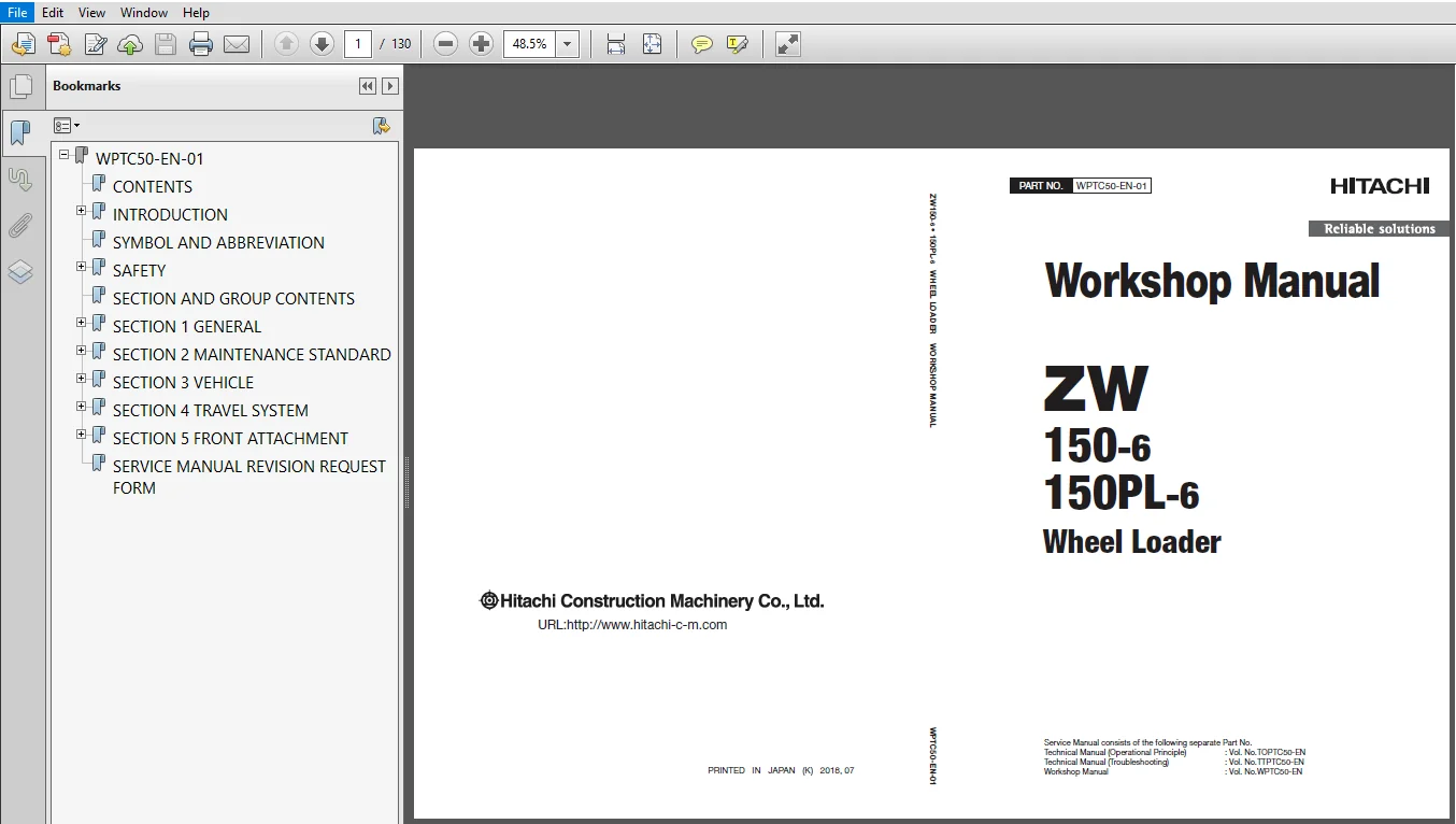
SCREENSHOTS OF THE MANUAL:
DESCRIPTION:
Hitachi ZW150-6 150PL-6 Wheel Loader Workshop + Operational Principle + Troubleshooting + Electrical-Hydraulic Circuit Manual
- This manual is written for an experienced technician to provide technical information needed to maintain and repair this machine.
- Be sure to thoroughly read this manual for correct product information and service procedures.
- If you have any questions or comments, at if you found any errors regarding the contents of this manual, please contact using “Service Manual Revision Request Form” at the end of this manual.
- This manual consists the Technical Manual and the Workshop Manual.
- Information included in the Technical Manual: technical information needed for redelivery and delivery, operation and activation of all devices and systems, operational performance tests, and troubleshooting procedures.
- Information included in the Workshop Manual: technical information needed for maintenance and repair of the machine, tools and devices needed for maintenance and repair, maintenance standards, and removal/installation and assemble/ disassemble procedures.
TABLE OF CONTENTS:
Hitachi ZW150-6 150PL-6 Wheel Loader Workshop Manual
Group 1 Precautions for Disassembling and
Assembling
Precautions for Disassembling and
Assembling…………………………………………………………W1-1-1-1
Group 2 Tightening
Tightening Bolts and Nuts…………………………………….W1-2-1-1
Piping Joint……………………………………………………………..W1-2-1-4
Group 3 Painting
Painting……………………………………………………………………W1-3-1-1
Painting (Parallel Link)……………………………………………W1-3-2-1
Group 4 Bleed Air from Circuit
Bleeding Air from Hydraulic System……………………W1-4-1-1
Bleeding Air from Fuel System……………………………..W1-4-1-3
Bleeding Air from Brake (Axle)……………………………..W1-4-1-4
Group 5 Preparation
Preparation before Inspection and
Maintenance………………………………………………………W1-5-1-1
Hydraulic Circuit Pressure Release Procedure……W1-5-1-6
Pressure Release from Ride Control
Accumulator……………………………………………………….W1-5-1-7
Pressure Release from Hydraulic Oil Tank…………..W1-5-1-8
Pressure Release from Expansion Tank……………….W1-5-1-9
Group 1 Body
Center Hinge…………………………………………………………..W2-1-1-1
Group 2 Front Attachment
Pin and Bushing………………………………………………………W2-2-1-1
Standard Dimensions for Lift Arm and Bucket…..W2-2-2-1
Cylinder……………………………………………………………………W2-2-3-1
Group 3 Front Attachment (Parallel Link)
Pin and Bushing………………………………………………………W2-3-1-1
Standard Dimensions for Quick Coupler and
Bucket………………………………………………………………….W2-3-2-1
Cylinder……………………………………………………………………W2-3-3-1
Group 1 Cab
Removal and Installation of Cab………………………….W3-1-1-1
Group 2 Counterweight
Removal and Installation of Counterweight………W3-2-1-1
Removal and Installation of Counterweight
(Parallel Link)………………………………………………………W3-2-2-1
Group 3 Center Hinge
Removal and Installation of Center Hinge………….W3-3-1-1
Removal and Installation of Center Hinge
(Parallel Link)………………………………………………………W3-3-2-1
Group 4 Engine
Removal and Installation of Engine…………………….W3-4-1-1
Removal and Installation of Cab………………………….W3-4-1-2
Group 5 Radiator Assembly
Removal and Installation of Radiator
Assembly…………………………………………………………….W3-5-1-1
Group 6 Hydraulic Oil Tank
Removal and Installation of Hydraulic Oil
Tank……………………………………………………………………..W3-6-1-1
Group 7 Fuel Tank
Removal and Installation of Fuel Tank…………………W3-7-1-1
Group 8 Pump Device
Removal and Installation of Pump Device………….W3-8-1-1
Removal and Installation of Cab………………………….W3-8-1-2
Disassembly of HST Pump…………………………………….W3-8-2-1
Assembly of HST Pump………………………………………….W3-8-2-5
Disassembly of 3-Gear Pump……………………………….W3-8-3-1
Assembly of 3-Gear Pump…………………………………….W3-8-3-6
Removal and Installation of Priority Valve………….W3-8-4-1
Structure of Priority Valve……………………………………..W3-8-5-1
Group 9 Control Valve
Removal and Installation of Control Valve………….W3-9-1-1
Removal and Installation of Control Valve
(Parallel Link)………………………………………………………W3-9-2-1
Disassembly of Control Valve (Parallel Link)……….W3-9-3-1
Assembly of Control Valve (Parallel Link)…………W3-9-3-10
Group 10 Pilot Valve
Removal and Installation of Pilot Valve…………….W3-10-1-1
Disassembly of Pilot Valve………………………………….W3-10-2-1
Assembly of Pilot Valve……………………………………….W3-10-2-4
Removal and Installation of Auxiliary Pilot
Valve………………………………………………………………….W3-10-3-1
Disassembly of Pilot Valve………………………………….W3-10-4-1
Assembly of Pilot Valve……………………………………….W3-10-4-4
Disassembly of Pilot Valve (Two Lever Type)……W3-10-5-1
Assembly of Pilot Valve (Two Lever Type)………..W3-10-5-7
Disassembly of Auxiliary Pilot Valve………………….W3-10-6-1
Assembly of Auxiliary Pilot Valve………………………W3-10-6-4
Group 11 Brake Charge Valve
Removal and Installation of Brake Charge
Valve………………………………………………………………….W3-11-1-1
Structure of Brake Charge Valve………………………..W3-11-2-1
Removal and Installation of Brake
Accumulator…………………………………………………….W3-11-3-1
Group 12 Manifold Valve
Removal and Installation of Manifold Valve…….W3-12-1-1
Disassembly of Manifold Valve………………………….W3-12-2-1
Assembly of Manifold Valve……………………………….W3-12-2-3
Group 13 Solenoid Valve
Removal and Installation of Front Attachment
Load Reduction Control Solenoid Valve……..W3-13-1-1
Structure of Front Attachment Load
Reduction Control Solenoid Valve……………….W3-13-2-1
Removal and Installation of Coupler Cylinder
Selector Solenoid Valve (Parallel Link)…………W3-13-3-1
Structure of Coupler Cylinder Selector
Solenoid Valve…………………………………………………W3-13-4-1
Removal and Installation of Quick Coupler
Pilot Solenoid Valve (Parallel Link)……………….W3-13-5-1
Group 15 Cooling Fan System
Removal and Installation of Fan Valve………………W3-15-1-1
Structure of Fan Valve………………………………………….W3-15-2-1
Removal and Installation of Fan Motor…………….W3-15-3-1
Structure of Fan Motor………………………………………..W3-15-4-1
Removal and Installation of Fan Pump…………….W3-15-5-1
Disassembly of Fan Pump…………………………………..W3-15-6-1
Assembly of Fan Pump……………………………………….W3-15-6-3
Group 16 Ride Control Device
Removal and Installation of Ride Control
Valve………………………………………………………………….W3-16-1-1
Removal and Installation of Ride Control
Valve (Parallel Link)…………………………………………W3-16-2-1
Disassembly of Ride Control Valve……………………W3-16-3-1
Assembly of Ride Control Valve…………………………W3-16-3-4
Removal and Installation of Ride Control
Accumulator…………………………………………………….W3-16-4-1
Group 17 Battery Disconnect Switch
Removal and Installation of Battery
Disconnect Switch………………………………………….W3-17-1-1
Group 18 Aftertreatment Device
Removal and Installation of Aftertreatment
Device……………………………………………………………….W3-18-1-1
Group 19 DEF Tank
Removal and Installation of DEF Tank………………W3-19-1-1
Group 20 Coolant Control Valve
Removal and Installation of Coolant Control
Valve………………………………………………………………….W3-20-1-1
Group 21 DEF Supply Module
Removal and Installation of DEF Supply
Module……………………………………………………………..W3-21-1-1
Group 22 Exterior Parts
Removal and Installation of Exterior Parts……….W3-22-1-1
Group 23 Parallel Link (Special Parts)
Removal and Installation of Bucket
Regenerative Valve ………………………………………..W3-23-1-1
Structure of Bucket Regenerative Valve…………..W3-23-2-1
Removal and Installation of Bucket
Regenerative Selector Valve………………………….W3-23-3-1
Structure of Bucket Regenerative Selector
Valve………………………………………………………………….W3-23-4-1
Group 1 Tire
Removal and Installation of Front Tire………………..W4-1-1-1
Removal and Installation of Rear Tire………………….W4-1-2-1
Group 2 Drive Unit
Removal and Installation of HST Motor………………W4-2-1-1
Disassembly of HST Motors 1, 2……………………………W4-2-2-1
Assembly of HST Motors 1, 2………………………………..W4-2-2-3
Removal and Installation of Transmission………….W4-2-3-1
Disassembly of Transmission………………………………..W4-2-4-1
Assembly of Transmission…………………………………..W4-2-4-10
Disassembly of Clutch Assembly…………………………W4-2-5-1
Assembly of Clutch Assembly………………………………W4-2-5-3
Disassembly of Clutch Pressure Control
Solenoid Valve……………………………………………………W4-2-6-1
Assembly of Clutch Pressure Control Solenoid
Valve…………………………………………………………………….W4-2-6-3
Group 3 Axle
Removal and Installation of Front Axle……………….W4-3-1-1
Removal and Installation of Rear Axle…………………W4-3-2-1
Disassembly of Axle……………………………………………….W4-3-3-1
Assembly of Axle………………………………………………….W4-3-3-17
Group 4 Propeller Shaft
Removal and Installation of Propeller Shaft……….W4-4-1-1
Group 5 Brake Valve
Removal and Installation of Brake Valve……………..W4-5-1-1
Disassembly of Brake Valve…………………………………..W4-5-2-1
Assembly of Brake Valve………………………………………..W4-5-2-3
Group 6 Steering Device
Removal and Installation of Steering Valve………..W4-6-1-1
Disassembly of Steering Valve……………………………..W4-6-2-1
Assembly of Steering Valve…………………………………..W4-6-2-4
Removal and Installation of Steering Cylinder…..W4-6-3-1
Disassembly of Steering Cylinder………………………..W4-6-4-1
Assembly of Steering Cylinder……………………………..W4-6-4-5
Removal and Installation of Steering
Accumulator……………………………………………………….W4-6-5-1
Group 7 Emergency Steering Device
Removal and Installation of Emergency
Steering Pump……………………………………………………W4-7-1-1
Group 1 Front Attachment
Removal and Installation of Front Attachment….W5-1-1-1
Removal and Installation of Bell Crank……………….W5-1-2-1
Removal and Installation of Bucket……………………..W5-1-3-1
Removal and Installation of Bushing…………………..W5-1-4-1
Group 2 Cylinder
Removal and Installation of Lift Arm Cylinder……W5-2-1-1
Removal and Installation of Bucket Cylinder……..W5-2-2-1
Disassembly of Lift Arm Cylinder…………………………W5-2-3-1
Assembly of Lift Arm Cylinder………………………………W5-2-3-5
Disassembly of Bucket Cylinder…………………………..W5-2-4-1
Assembly of Bucket Cylinder ……………………………….W5-2-4-5
Group 3 Front Attachment (Parallel Link)
Removal and Installation of Front Attachment….W5-3-1-1
Removal and Installation of Quick Coupler………..W5-3-2-1
Group 4 Cylinder (Parallel Link)
Removal and Installation of Lift Arm Cylinder……W5-4-1-1
Removal and Installation of Bucket Cylinder……..W5-4-2-1
Removal and Installation of Quick Coupler
Cylinder……………………………………………………………….W5-4-3-1
Disassembly of Lift Arm Cylinder…………………………W5-4-4-1
Assembly of Lift Arm Cylinder………………………………W5-4-4-5
Disassembly of Bucket Cylinder…………………………..W5-4-5-1
Assembly of Bucket Cylinder………………………………..W5-4-5-4
Disassembly of Quick Coupler Cylinder………………W5-4-6-1
Assembly of Quick Coupler Cylinder…………………..W5-4-6-4
Hitachi ZW150-6 150PL-6 Wheel Loader Operational Principle Manual
SECTION 1 GENERAL
Group 1 Specifications
Group 2 Component Layout
Group 3 Component Specifications
SECTION 2 SYSTEM
Group 1 Controller
Group 2 Control System
Group 3 ECM System
Group 4 Hydraulic System
Group 5 Electrical System
SECTION 3 COMPONENT OPERATION
Group 1 Pump Device
Group 2 Control Valve
Group 3 Cooling Fan System
Group 4 Steering Valve
Group 5 HST Motor
Group 6 Pilot Valve
Group 7 Brake Charge Valve/Manifold Valve
Group 8 Transmission
Group 9 Axle
Group 10 Brake Valve
Group 11 Priority Valve
Group 12 Ride Control Valve
Group 13 Others
Hitachi ZW150-6 150PL-6 Wheel Loader Troubleshooting Manual
SECTION 4 OPERATIONAL
PERFORMANCE TEST
Group 1 Introduction
Group 2 Standard
Group 3 Engine Test
Group 4 Machine Performance Test
Group 5 Component Test
Group 6 Adjustment
SECTION 5 TROUBLESHOOTING
Group 1 Diagnosing Procedure
Group 2 Monitor
Group 3 e-Service
Group 4 Component Layout
Group 5 Troubleshooting A
Group 6 Troubleshooting B
Group 7 Troubleshooting C
Group 8 Air Conditioner
PLEASE NOTE:
- This is the same manual used by the DEALERSHIPS to SERVICE your vehicle.
- The manual can be all yours – Once payment is complete, you will be taken to the download page from where you can download the manual. All in 2-5 minutes time!!
- Need any other service / repair / parts manual, please feel free to contact us at heydownloadss @gmail.com . We may surprise you with a nice offer