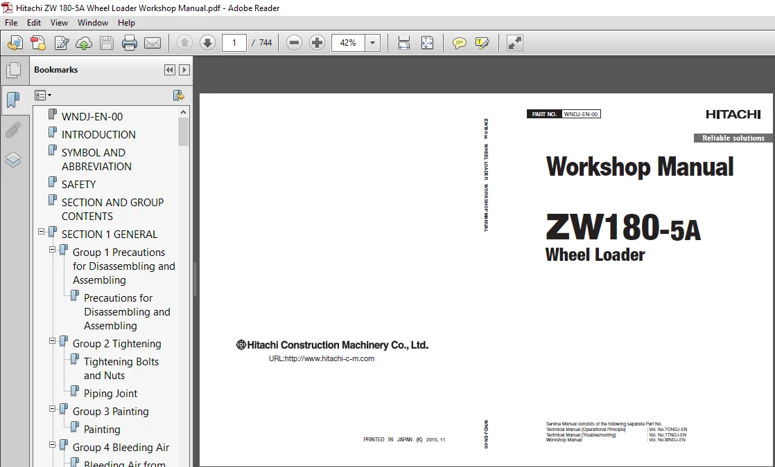
Hitachi ZW180-5A Wheel Loader Workshop Manual (WNDJ-EN-00) – PDF Download
Original price was: $79.95.$27.95Current price is: $27.95.
- Hitachi ZW180-5A Wheel Loader Workshop Manual
- Part No:WNDJ-EN-00
Description
Hitachi ZW180-5A Wheel Loader Workshop Manual (WNDJ-EN-00)
File Details:
Hitachi ZW180-5A Wheel Loader Workshop Manual (WNDJ-EN-00)
- Manual Language:English
- Pages: 744
- Size: 7.00 MB
- Downloadable:Yes
- Format:PDF
HITACHI ZW180-5A WHEEL LOADER WORKSHOP MANUAL (WNDJ-EN-00) – PDF DOWNLOAD:
Image Preview:
Description:
Hitachi ZW180-5A Wheel Loader Workshop Manual (WNDJ-EN-00)
To The Reader
This manual is written for an experienced technician to provide technical information needed to maintain and repair this machine.
The machine specification and description according to destination may be explained on this manual.
Be sure to thoroughly read this manual for correct product information and service procedures.
If you have any questions or comments, at if you found any errors regarding the contents of this manual, please contact using “Service Manual Revision Request Form” at the end of this manual.
Additional References
Please refer to the other materials (operator’s manual, parts catalog, engine technical material and Hitachi training material etc.) in addition to this manual.
Manual Composition
This manual consists the Technical Manual, the Workshop Manual and the Engine Manual.
Information included in the Technical Manual: Technical information needed for redelivery and delivery, operation and activation of all devices and systems, operational performance tests, and troubleshooting procedures.
Information included in the Workshop Manual: Technical information needed for maintenance and repair of the machine, tools and devices needed for maintenance and repair, maintenance standards, and removal / installation and assemble / disassemble procedures.
Information included in the Engine Manual: Technical information needed for redelivery and delivery and maintenance and repair of the machine, operation and activation of all devices and systems, troubleshooting and assemble / disassemble procedures.
Table Of Contents:
Hitachi ZW180-5A Wheel Loader Workshop Manual (WNDJ-EN-00)
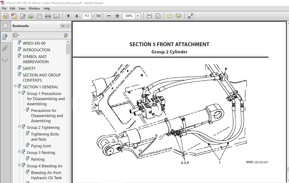
WNDJ-EN-00............................................................................................  1
INTRODUCTION..........................................................................................  3
SYMBOL AND ABBREVIATION...............................................................................  5
SAFETY................................................................................................  7
SECTION AND GROUP CONTENTS............................................................................ 47
SECTION 1 GENERAL..................................................................................... 51
	Group 1 Precautions for Disassembling and Assembling.............................................. 53
		Precautions for Disassembling and Assembling.................................................. 53
	Group 2 Tightening................................................................................ 59
		Tightening Bolts and Nuts..................................................................... 59
		Piping Joint.................................................................................. 62
	Group 3 Painting.................................................................................. 69
		Painting...................................................................................... 69
	Group 4 Bleeding Air.............................................................................. 77
		Bleeding Air from Hydraulic Oil Tank.......................................................... 77
		Bleeding Air from Hydraulic System............................................................ 78
		Bleeding Air from Fuel System................................................................. 79
		Bleeding Air from Radiator.................................................................... 80
		Bleeding Air from Brake (Axle)................................................................ 81
	Group 5 Releasing Pressure........................................................................ 83
		Front Attachment Hydraulic Circuit Pressure Release Procedure................................. 83
		Ride Control Accumulator Pressure Release Procedure........................................... 84
		Parking Brake Accumulator Pressure Release Procedure.......................................... 85
	Group 6 Preparation............................................................................... 87
		Preparation before Inspection and Maintenance................................................. 87
SECTION 2 MAINTENANCE STANDARD........................................................................ 93
	Group 1 Body...................................................................................... 95
		Center Hinge.................................................................................. 95
	Group 2 Front Attachment.......................................................................... 97
		Pin and Bushing............................................................................... 97
		Standard Dimensions for Lift Arm and Bucket................................................... 99
		Cylinder......................................................................................101
SECTION 3 BODY........................................................................................105
	Group 1 Cab.......................................................................................107
		Removal and Installation of Cab...............................................................107
	Group 2 Counterweight.............................................................................141
		Removal and Installation of Counterweight.....................................................141
		Removal and Installation of Battery Box.......................................................143
	Group 3 Center Hinge..............................................................................147
		Removal and Installation of Center Hinge......................................................147
	Group 4 Engine....................................................................................169
		Removal and Installation of Engine............................................................169
		Removal And Installation of Exterior Parts....................................................215
	Group 5 Radiator Assembly.........................................................................227
		Removal and Installation of Radiator, Oil Cooler, Intercooler, and Torque Converter Cooler....227
	Group 6 Hydraulic Oil Tank........................................................................257
		Removal and Installation of Hydraulic Oil Tank................................................257
	Group 7 Fuel Tank.................................................................................277
		Removal and Installation of Fuel Tank.........................................................277
	Group 8 Pump Device...............................................................................283
		Removal and Installation of Pump Device.......................................................283
		Disassembly of Pump Device....................................................................291
		Assembly of Pump Device.......................................................................293
		Disassembly of Main Pump......................................................................295
		Assembly of Main Pump.........................................................................299
		Disassembly of Regulator......................................................................305
		Assembly of Regulator.........................................................................307
		Structure of Pilot Pump.......................................................................309
	Group 9 Control Valve.............................................................................311
		Removal and Installation of Control Valve.....................................................311
		Disassembly of Control Valve..................................................................321
		Assembly of Control Valve.....................................................................325
	Group 10 Pilot Valve..............................................................................331
		Removal and Installation of Pilot Valve.......................................................331
		Removal and Installation of Pilot Valve (Two Lever Type ).....................................337
		Disassembly of Pilot Valve....................................................................343
		Assembly of Pilot Valve.......................................................................346
		Disassembly of Pilot Valve (Two Lever Type)...................................................351
		Assembly of Pilot Valve (Two Lever Type)......................................................357
	Group 11 Brake Charge Valve.......................................................................365
		Removal and Installation of Brake Charge Valve................................................365
		Structure of Brake Charge Valve...............................................................371
		Removal and Installation of BrakeAccumulator..................................................373
	Group 12 Manifold Valve...........................................................................379
		Removal and Installation of Manifold Valve....................................................379
		Disassembly of Manifold Valve.................................................................389
		Assembly of Manifold Valve....................................................................392
	Group 13 Solenoid Valve...........................................................................397
		Removal and Installation of Parking Brake Solenoid Valve Unit.................................397
		Structure of Parking Brake Solenoid Valve Unit................................................401
	Group 14 Priority Valve...........................................................................403
		Removal and Installation of Priority Val......................................................403
		Structure of Priority Valve...................................................................415
	Group 15 Cooling Fan System.......................................................................417
		Removal and Installation of Fan Motor.........................................................417
		Structure of Fan Motor........................................................................433
		Removal and Installation of Fan Pump..........................................................435
		Disassembly of Fan Pump.......................................................................441
		Assembly of Fan Pump..........................................................................443
	Group 16 Ride Control Device......................................................................447
		Removal and Installation of Ride Control Valve................................................447
		Disassembly of Ride Control Valve.............................................................451
		Assembly of Ride Control Valve................................................................454
		Removal and Installation of Ride Control Accumulator..........................................459
SECTION 4 TRAVEL SYSTEM...............................................................................465
	Group 1 Tire......................................................................................467
		Removal and Installation of Front Tire........................................................467
		Removal and Installation of Rear Tire.........................................................471
	Group 2 Drive Unit................................................................................475
		Removal and Installation of Drive Unit........................................................481
		Disassembly and Assembly of Drive Unit........................................................481
		Removal and Installation of Torque Converter..................................................487
		Disassembly and Assembly of Transmission......................................................493
		Disassembly and Assembly of Transmission Control Valve........................................543
		Removal and Installation of Parking Brake (Replace The Brake Friction Pad)....................557
	Group 3 Axle......................................................................................567
		Removal and Installation of Front Axle........................................................567
		Removal and Installation of Rear Axle.........................................................573
		Disassembly of Axle...........................................................................583
		Assembly of Axle..............................................................................584
	Group 4 Propeller Shaft...........................................................................585
		Removal and Installation of Propeller Shaft...................................................585
	Group 5 Brake Valve...............................................................................595
		Removal and Installation of Brake Valve (One Pedal)...........................................595
		Removal and Installation of Brake Valve (Two Pedals)..........................................601
		Disassembly of Brake Valve....................................................................607
		Assembly of Brake Valve.......................................................................610
	Group 6 Steering Device...........................................................................617
		Removal and Installation of Steering Valve....................................................617
		Disassembly of Steering Valve.................................................................621
		Assembly of Steering Valve....................................................................624
		Removal and Installation of Steering Cylinder.................................................629
		Disassembly of Steering Cylinder
.............................................................643
		Assembly of Steering Cylinder.................................................................647
		Removal and Installation of Steering Accumulator..............................................653
	Group 7 Emergency Steering Device.................................................................655
		Removal and Installation of Emergency Steering Pump...........................................655
SECTION 5 FRONT ATTACHMENT............................................................................663
	Group 1 Front Attachment..........................................................................665
		Removal and Installation of Front Attachment (With Lift Arm Kickout)..........................665
		Removal and Installation of Front Attachment (With Lift Arm Auto Leveler).....................679
		Removal and Installation of Bell Crank........................................................695
		Removal and Installation of Bucket............................................................705
	Group 2 Cylinder..................................................................................711
		Removal and Installation of Lift Arm Cylinder.................................................711
		Removal and Installation of Bucket Cylinder...................................................719
		Disassembly of Lift Arm Cylinder and Bucket Cylinder..........................................731
		Assembly of Lift Arm Cylinder and Bucket Cylinder.............................................736
SERVICE MANUAL REVISION REQUEST FORM..................................................................743
Please Note:
⦁ This is the SAME MANUAL used by the dealerships to diagnose your vehicle
⦁ No waiting for couriers / posts as this is a PDF manual and you can download it within 2 minutes time once you make the payment.
⦁ Your payment is all safe and the delivery of the manual is INSTANT – You will be taken to the DOWNLOAD PAGE.
⦁ So have no hesitations whatsoever and write to us about any queries you may have : heydownloadss @gmail.com