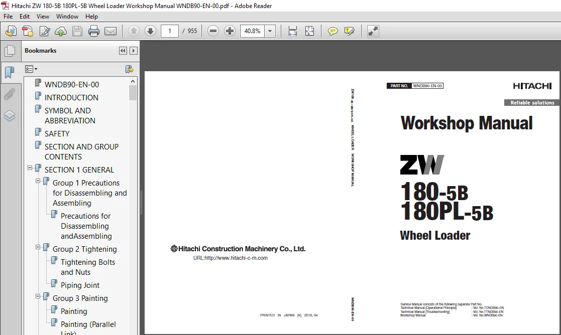
Hitachi ZW180-5B ZW180PL-5B Wheel Loader Workshop Manual (WNDB90-EN-00) – PDF Download
Original price was: $89.95.$26.95Current price is: $26.95.
- Hitachi ZW180-5B ZW180PL-5B Wheel Loader Workshop Manual
- Part No:WNDB90-EN-00
Description
Hitachi ZW180-5B ZW180PL-5B Wheel Loader Workshop Manual (WNDB90-EN-00)
File Details:
Hitachi ZW180-5B ZW180PL-5B Wheel Loader Workshop Manual (WNDB90-EN-00)
- Manual Language:English
- Downloadable:Yes
- Pages: 955
- Size: 34.5 MB
- Format:PDF
HITACHI ZW180-5B ZW180PL-5B WHEEL LOADER WORKSHOP MANUAL (WNDB90-EN-00) – PDF DOWNLOAD:
Image Preview:
Description:
Hitachi ZW180-5B ZW180PL-5B Wheel Loader Workshop Manual (WNDB90-EN-00)
To The Reader
This manual is written for an experienced technician to provide technical information needed to maintain and repair this machine.
The machine specification and description according to destination may be explained on this manual.
Be sure to thoroughly read this manual for correct product information and service procedures.
If you have any questions or comments, at if you found any errors regarding the contents of this manual, please contact using “Service Manual Revision Request Form” at the end of this manual.
Additional References
Please refer to the other materials (operator’s manual, parts catalog, engine technical material and Hitachi training material etc.) in addition to this manual.
Manual Composition
This manual consists the Technical Manual, the Workshop Manual and the Engine Manual.
Information included in the Technical Manual: Technical information needed for redelivery and delivery, operation and activation of all devices and systems, operational performance tests, and troubleshooting procedures.
Information included in the Workshop Manual: Technical information needed for maintenance and repair of the machine, tools and devices needed for maintenance and repair, maintenance standards, and removal / installation and assemble / disassemble procedures.
Information included in the Engine Manual: Technical information needed for redelivery and delivery and maintenance and repair of the machine, operation and activation of all devices and systems, troubleshooting and assemble / disassemble procedures.
Table Of Contents:
Hitachi ZW180-5B ZW180PL-5B Wheel Loader Workshop Manual (WNDB90-EN-00)
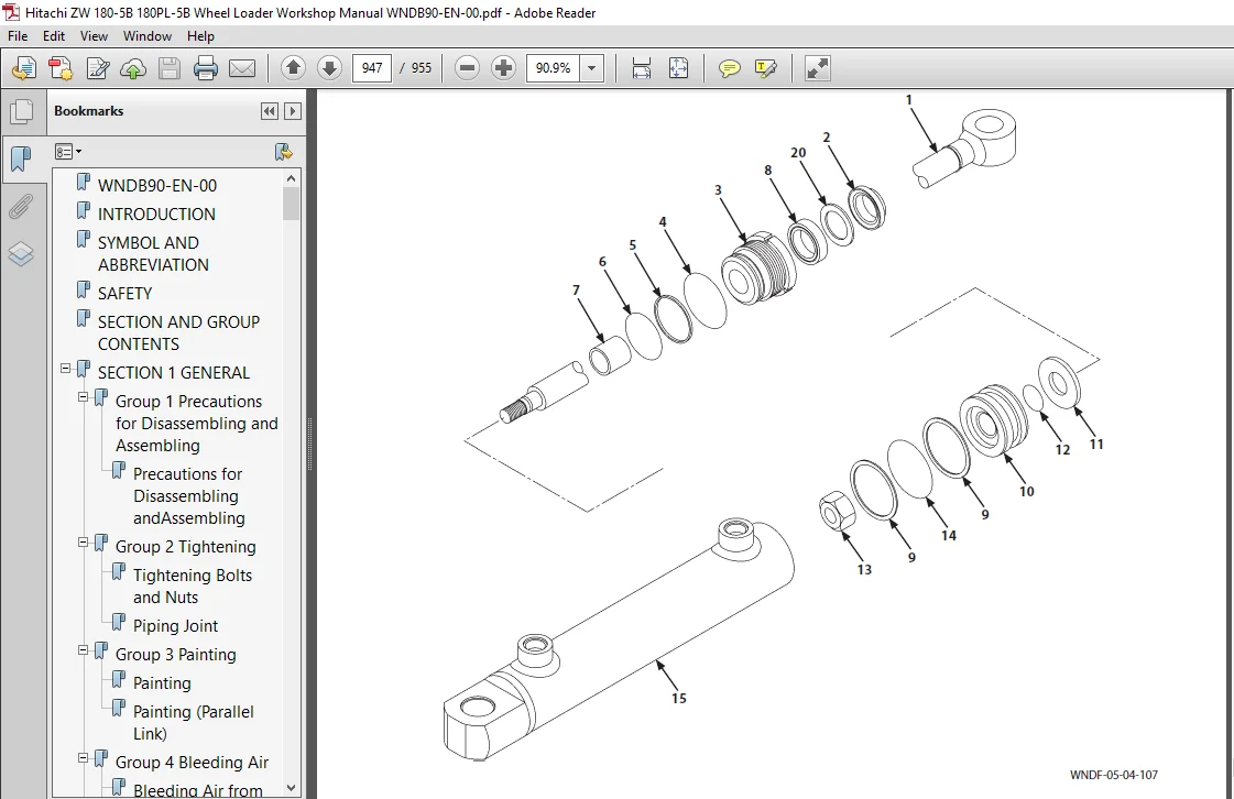
WNDB90-EN-00........................................................................................  1
INTRODUCTION........................................................................................  3
SYMBOL AND ABBREVIATION.............................................................................  5
SAFETY..............................................................................................  7
SECTION AND GROUP CONTENTS.......................................................................... 47
SECTION 1 GENERAL................................................................................... 51
	Group 1 Precautions for Disassembling and Assembling............................................ 53
		Precautions for Disassembling andAssembling................................................. 53
	Group 2 Tightening.............................................................................. 59
		Tightening Bolts and Nuts................................................................... 59
		Piping Joint................................................................................ 62
	Group 3 Painting................................................................................ 69
		Painting.................................................................................... 69
		Painting (Parallel Link).................................................................... 75
	Group 4 Bleeding Air............................................................................ 85
		Bleeding Air from Hydraulic Oil Tank........................................................ 85
		Bleeding Air from Hydraulic System.......................................................... 86
		Bleeding Air from Fuel System............................................................... 87
		Bleeding Air from Radiator.................................................................. 88
		Bleeding Air from Brake (Axle).............................................................. 89
	Group 5 Releasing Pressure...................................................................... 91
		Front Attachment Hydraulic Circuit PressureRelease Procedure................................ 91
		Ride Control Accumulator Pressure Release Procedure......................................... 92
		Parking Brake Accumulator Pressure Release Procedure........................................ 93
	Group 6 Preparation............................................................................. 95
		Preparation before Inspection andMaintenance................................................ 95
SECTION 2 MAINTENANCE STANDARD......................................................................101
	Group 1 Body....................................................................................103
		Center Hinge................................................................................103
	Group 2 Travel System...........................................................................105
		Axle........................................................................................105
	Group 3 Front Attachment........................................................................109
		Pin and Bushing.............................................................................109
		Standard Dimensions for Lift Arm and Bucket.................................................111
		Cylinder....................................................................................113
	Group 4 Front Attachment (Parallel Link)........................................................115
		Pin and Bushing.............................................................................115
		Standard Dimensions for Quick Coupler and Bucket............................................117
		Cylinder....................................................................................119
SECTION 3 BODY......................................................................................123
	Group 1 Cab.....................................................................................125
		Removal and Installation of Cab.............................................................125
		Removal and Installation of Cab (Parallel Link).............................................147
	Group 2 Counterweight...........................................................................169
		Removal and Installation of Counterweight...................................................169
		Removal and Installation of Battery Box (Without Battery Disconnect Switch).................171
		Removal and Installation of Battery Box (Attached Battery Disconnect Switch)................175
		Removal and Installation of Battery Disconnect Switch.......................................179
	Group 3 Center Hinge............................................................................183
		Removal and Installation of Center Hinge....................................................183
		Removal and Installation of Center Hinge (Parallel Link)....................................205
	Group 4 Engine..................................................................................231
		Removal and Installation of Engine..........................................................231
		Removal And Installation of Exterior Parts..................................................261
		Removal and Installation of the air cleaner.................................................277
	Group 5 Radiator Assembly.......................................................................281
		Replacement of Radiator, Oil Cooler,Intercooler, Torque Converter Cooler, andFuel Cooler....281
	Group 6 Hydraulic Oil Tank......................................................................295
		Removal and Installation of Hydraulic OilTank...............................................295
	Group 7 Fuel Tank...............................................................................307
		Removal and Installation of Fuel Tank.......................................................307
	Group 8 Pump Device.............................................................................315
		Removal and Installation of Pump Device.....................................................315
		Disassembly of Pump Device..................................................................323
		Assembly of Pump Device.....................................................................325
		Disassembly of Main Pump....................................................................327
		Assembly of Main Pump.......................................................................331
		Disassembly of Regulator....................................................................337
		Assembly of Regulator.......................................................................339
		Structure of Pilot Pump.....................................................................341
	Group 9 Control Valve...........................................................................343
		Removal and Installation of Control Valve...................................................343
		Removal and Installation of Control Valve (Parallel Link)...................................353
		Disassembly of Control Valve................................................................365
		Assembly of Control Valve...................................................................369
		Disassembly of Control Valve (Parallel Link)................................................375
		Assembly of Control Valve (Parallel Link)...................................................384
	Group 10 Pilot Valve............................................................................393
		Removal and Installation of Pilot Valve.....................................................393
		Removal and Installation of Pilot Valve (Two Lever Type )...................................399
		Removal and Installation of Auxiliary Pilot Valve...........................................405
		Disassembly of Pilot Valve..................................................................411
		Assembly of Pilot Valve.....................................................................414
		Disassembly of Pilot Valve (Two Lever Type).................................................419
		Assembly of Pilot Valve (Two Lever Type)....................................................425
		Disassembly of Auxiliary Pilot Valve........................................................433
		Assembly of Auxiliary Pilot Valve...........................................................436
	Group 11 Brake Charge Valve.....................................................................441
		Removal and Installation of Brake ChargeValve...............................................441
		Structure of Brake Charge Valve.............................................................447
		Removal and Installation of Brake Accumulator...............................................449
	Group 12 Manifold Valve.........................................................................455
		Removal and Installation of Manifold Valve..................................................455
		Disassembly of Manifold Valve...............................................................465
		Assembly of Manifold Valve..................................................................468
	Group 13 Solenoid Valve.........................................................................473
		Removal and Installation of Parking BrakeSolenoid Valve Unit................................473
		Structure of Parking Brake Solenoid Valve Unit..............................................477
		Removal and Installation of Quick Coupler Solenoid Valve (Parallel Link)....................479
		Disassembly of Quick Coupler Solenoid Valve.................................................487
		Assembly of Quick Coupler Solenoid Valve....................................................489
	Group 14 Priority Valve.........................................................................491
		Removal and Installation of Priority Valve..................................................491
		Structure of Priority Valve.................................................................495
	Group 15 Cooling Fan System.....................................................................497
		Removal and Installation of Fan Valve.......................................................497
		Structure of Fan Valve......................................................................501
		Removal and Installation of Fan Motor.......................................................503
		Structure of Fan Motor......................................................................519
		Removal and Installation of Fan Pump........................................................521
		Disassembly of Fan Pump.....................................................................527
		Assembly of Fan Pump........................................................................529
	Group 16 Ride Control Device....................................................................533
		Removal and Installation of Ride ControlValve...............................................533
		Disassembly of Ride Control Valve...........................................................537
		Assembly of Ride Control Valve..............................................................540
		Removal and Installation of Ride Control Accumulator........................................545
	Group 17 Parallel Link (Special Parts)..........................................................549
		Removal and Installation of BucketRegenerative Valve........................................549
		Structure of Bucket Regenerative Valve......................................................559
		Removal and Installation of Bucket Regenerative Selector Valve..............................561
		Structure of Bucket Regenerative Selector Valve.............................................567
SECTION 4 TRAVEL SYSTEM.............................................................................571
	Group 1 Tire....................................................................................573
		Removal and Installation of Front Tire......................................................573
		Removal and Installation of Rear Tire.......................................................577
	Group 2 Drive Unit..............................................................................583
		Removal and Installation of Drive Unit......................................................583
		Disassembly and Assembly of Drive Unit......................................................589
		Removal and Installation of Torque Converter................................................595
		Disassembly and Assembly of Transmission....................................................601
		Disassembly and Assembly of Transmission Control Valve......................................651
		Removal and Installation of Parking Brake (Replace The Brake Friction Pad)..................665
	Group 3 Axle....................................................................................675
		Removal and Installation of Front Axle......................................................675
		Removal and Installation of Rear Axle.......................................................683
		Disassembly of Axle.........................................................................691
		Assembly of Axle............................................................................708
	Group 4 Propeller Shaft.........................................................................735
		Removal and Installation of Propeller Shaft.................................................735
	Group 5 Brake Valve.............................................................................745
		Removal and Installation of Brake Valve.....................................................745
		Disassembly of Brake Valve..................................................................749
		Assembly of Brake Valve.....................................................................751
	Group 6 Steering Device.........................................................................755
		Removal and Installation of Steering Valve..................................................755
		Disassembly of Steering Valve...............................................................759
		Assembly of Steering Valve..................................................................762
		Removal and Installation of Steering Cylinder...............................................767
		Disassembly of Steering Cylinder............................................................781
		Assembly of Steering Cylinder...............................................................785
		Removal and Installation of Steering Accumulator............................................791
	Group 7 Emergency Steering Device...............................................................793
		Removal and Installation of Emergency Steering Pump.........................................793
SECTION 5 FRONT ATTACHMENT..........................................................................801
	Group 1 Front Attachment........................................................................803
		Removal and Installation of Front Attachment (With Lift Arm Kickout)........................803
		Removal and Installation of Front Attachment (With Lift Arm Auto Leveler)...................817
		Removal and Installation of Bell Crank......................................................831
		Removal and Installation of Bucket..........................................................841
	Group 2 Cylinder................................................................................847
		Removal and Installation of Lift Arm Cylinder...............................................847
		Removal and Installation of Bucket Cylinder.................................................855
		Disassembly of Lift Arm Cylinder and Bucket Cylinder........................................867
		Assembly of Lift Arm Cylinder and Bucket Cylinder...........................................872
	Group 3 Front Attachment (Parallel Link)........................................................877
		Removal and Installation of FrontAttachment.................................................877
		Removal and Installation of Quick Coupler...................................................899
	Group 4 Cylinder (Parallel Link)................................................................907
		Removal and Installation of Lift Arm Cylinder...............................................907
		Removal and Installation of Bucket Cylinder.................................................915
		Removal and Installation of Quick Coupler Cylinder..........................................927
		Disassembly of Lift Arm Cylinder............................................................931
		Assembly of Lift Arm Cylinder...............................................................935
		Disassembly of Bucket Cylinder..............................................................939
		Assembly of Bucket Cylinder.................................................................943
		Disassembly of Quick Coupler Cylinder.......................................................947
		Assembly of Quick Coupler Cylinder..........................................................950
SERVICE MANUAL REVISION REQUEST FORM................................................................955
Please Note:
⦁ This is the SAME exact manual used by your dealers to fix your vehicle.
⦁ The same can be yours in the next 2-3 mins as you will be directed to the download page immediately after paying for the manual.
⦁ Any queries / doubts regarding your purchase, please feel free to contact [email protected]