Hitachi ZW180-6 ZW180PL-6 Wheel Loader Operational Principle Technical Manual (TOPD850-EN-01) – PDF Download
Original price was: $81.95.$23.95Current price is: $23.95.
- Hitachi ZW180-6 ZW180PL-6 Wheel Loader Operational Principle Technical Manual
- Part No:TOPD850-EN-01
Description
Hitachi ZW180-6 ZW180PL-6 Wheel Loader Operational Principle Technical Manual (TOPD850-EN-01)
File Details:
Hitachi ZW180-6 ZW180PL-6 Wheel Loader Operational Principle Technical Manual (TOPD850-EN-01)
- Manual Language:English
- Pages: 505
- Size: 13.3 MB
- Downloadable:Yes
- Format:PDF
HITACHI ZW180-6 ZW180PL-6 WHEEL LOADER OPERATIONAL PRINCIPLE TECHNICAL MANUAL (TOPD850-EN-01) – PDF DOWNLOAD:
Image Preview:
Description:
Hitachi ZW180-6 ZW180PL-6 Wheel Loader Operational Principle Technical Manual (TOPD850-EN-01)
To The Reader
This manual is written for an experienced technician to provide technical information needed to maintain and repair this machine.
The machine specification and description according to destination may be explained on this manual.
Be sure to thoroughly read this manual for correct product information and service procedures.
If you have any questions or comments, at if you found any errors regarding the contents of this manual, please contact using “Service Manual Revision Request Form” at the end of this manual.
Additional References
Please refer to the other materials (operator’s manual, parts catalog, engine technical material and Hitachi training material etc.) in addition to this manual.
Manual Composition
This manual consists the Technical Manual, the Workshop Manual and the Engine Manual.
Information included in the Technical Manual:Technical information needed for redelivery and delivery, operation and activation of all devices and systems, operational performance tests, and troubleshooting procedures.
Information included in the Workshop Manual: Technical information needed for maintenance and repair of the machine, tools and devices needed for maintenance and repair, maintenance standards, and removal / installation and assemble / disassemble procedures.
Information included in the Engine Manual: Technical information needed for redelivery and delivery and maintenance and repair of the machine, operation and activation of all devices and systems, troubleshooting and assemble / disassemble procedures.
Table Of Contents:
Hitachi ZW180-6 ZW180PL-6 Wheel Loader Operational Principle Technical Manual (TOPD850-EN-01)
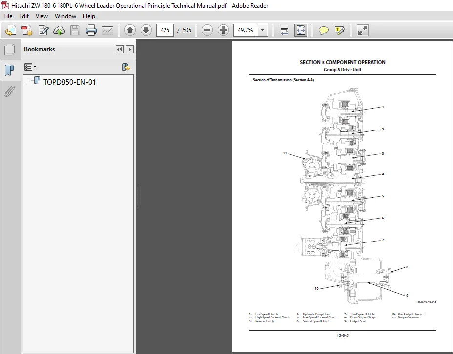
TOPD850-EN-01....................................................................  1
	INTRODUCTION.................................................................  3
		To The Reader............................................................  3
		Additional References....................................................  3
		Manual Composition.......................................................  3
		Page Number..............................................................  3
		Trademark................................................................  3
		Safety Alert Symbol and Headline Notations...............................  4
		Units Used...............................................................  4
	SYMBOL AND ABBREVIATION......................................................  5
	SECTION AND GROUP CONTENTS...................................................  7
	SECTION 1 GENERAL............................................................  9
		Group 1 Specifications................................................... 11
			Specifications....................................................... 11
		Group 2 Component Layout................................................. 13
			Main Component (Overview)............................................ 13
			Main Component....................................................... 16
			Electrical System (Overview)......................................... 19
			Air Cleaner and Radiator Assembly.................................... 20
			Battery Box.......................................................... 22
			Hydraulic Oil Tank................................................... 23
			Fuel Tank............................................................ 24
			Drive Unit........................................................... 25
			Front Axle........................................................... 26
			Cab.................................................................. 27
			Engine............................................................... 33
			Aftertreatment Device................................................ 34
			Fan Valve............................................................ 35
			Priority Valve....................................................... 35
			Pump Device.......................................................... 36
			Control Valve........................................................ 36
			Manifold Valve....................................................... 37
			Parking Brake Solenoid Valve Block................................... 37
			Brake Charge Valve................................................... 37
			Ride Control Valve................................................... 38
			Emergency (Secondary) Steering Block................................. 39
			Emergency Steering Pump.............................................. 39
			Flow Regulator Valve................................................. 39
			DEF Tank............................................................. 40
			DEF Supply Module.................................................... 40
		Group 3 Component Specifications......................................... 41
			Engine............................................................... 41
			Engine Accessories................................................... 45
			Hydraulic Component.................................................. 46
			Electrical Component................................................. 51
	SECTION 2 SYSTEM............................................................. 55
		Group 1 Controller....................................................... 57
			Outline.............................................................. 57
			CAN Circuit.......................................................... 58
		Group 2 Control System................................................... 61
			Outline.............................................................. 61
			Engine Control (ECM)................................................. 64
			Pump Control.........................................................103
			Transmission Control (TCU)...........................................108
			Forward/Reverse Lever Priority Control...............................112
			Fan Control, Valve Control...........................................127
			Control by Electrical and Hydraulic Combined Circuit.................157
		Group 3 Engine System....................................................163
			Outline..............................................................163
			ECM System...........................................................164
			Fuel Injection Control...............................................166
			Fuel Injection Amount Correction Control.............................174
			EGR Control..........................................................176
			Preheating Control...................................................178
			Variable Turbocharger Control........................................179
			Alarm Control........................................................180
			Urea SCR System......................................................181
			Engine Output Restriction Control (INDUCEMENT).......................192
			Aftertreatment Device................................................198
			Aftertreatment Device Regeneration Control...........................200
		Group 4 Hydraulic System.................................................203
			Outline..............................................................203
			Pilot Circuit........................................................204
			Main Circuit.........................................................226
			Fan Circuit..........................................................246
			Emergency (Secondary) Steering Circuit...............................248
		Group 5 Electrical System................................................251
			Outline..............................................................251
			Main Circuit.........................................................252
			Electric Power Circuit (Key Switch: OFF).............................254
			CAN Circuit..........................................................256
			Accessory Circuit (Key Switch: ACC)..................................258
			Starting Circuit (Key Switch: START).................................260
			Charging Circuit (Key Switch: ON)....................................262
			Surge Voltage Prevention Circuit.....................................266
			Pilot Shut-Off Circuit (Key Switch: ON)..............................268
			Auto Shut-Down (Idling Stop) Circuit.................................270
			Engine Stop Circuit..................................................272
			Air Conditioner Circuit..............................................274
			Steering Column Box Circuit..........................................277
			Headlight Circuit....................................................278
			Hazard Light Circuit (Key Switch: OFF)...............................284
			Turn Signal Light Circuit............................................286
			Horn Circuit (Key Switch: OFF).......................................288
			Back Buzzer Circuit..................................................290
			Brake Light Circuit..................................................292
			Parking Brake Circuit................................................294
			Accessory Circuit....................................................299
			Work Light Circuit...................................................300
			Wiper Circuit........................................................302
			Cab Light Circuit....................................................308
	SECTION 3 COMPONENT OPERATION................................................313
		Group 1 Pump Device......................................................315
			Outline..............................................................315
			Main Pump............................................................316
			Regulator............................................................318
			Pilot Pump...........................................................332
			Pump Delivery Pressure Sensor........................................332
		Group 2 Control Valve....................................................333
			Outline..............................................................333
			Hydraulic Circuit....................................................340
			Main Relief Valve....................................................346
			Overload Relief Valve (with Make-Up Function)........................348
			Overload Relief Valve (Lift Arm Bottom Side, Bucket Bottom Side).....352
			Flow Rate Control Valve..............................................356
			Pump Control Valve...................................................358
		Group 3 Cooling Fan System...............................................361
			Fan Pump.............................................................361
			Fan Motor............................................................362
			Fan Valve............................................................363
		Group 4 Steering Valve...................................................371
			Outline..............................................................371
			Structure............................................................372
			Operation............................................................373
			Overload Relief Valve................................................376
			Make-Up Valve........................................................378
		Group 5 Priority Valve...................................................381
			Outline..............................................................381
			Structure............................................................382
			Operation............................................................384
		Group 6 Pilot Valve......................................................391
			Outline (Fingertip Control Type Pilot Valve for Front Attachment)....391
			Operation............................................................392
			Electromagnetic Detent...............................................396
			Outline (Joystick Type Pilot Valve for Front Attachment).............397
			Operation............................................................399
			Electromagnetic Detent...............................................406
		Group 7 Brake Charge Valve / Manifold Valve..............................407
			Outline..............................................................407
			Brake Charge Valve...................................................408
			Manifold Valve.......................................................413
			Pilot Relief Valve...................................................414
			Torque Control Solenoid Valve........................................415
			Control Lever Lock Solenoid Valve....................................417
			Service Brake Accumulator............................................418
			Pilot Accumulator....................................................419
		Group 8 Drive Unit.......................................................421
			Outline..............................................................421
			Torque Converter.....................................................426
			Transmission.........................................................428
			Operation of Transmission............................................430
			Transmission Control Valve...........................................446
			Drive Unit Circuit...................................................448
			Parking Brake Manual Release.........................................449
		Group 9 Axle.............................................................451
			Outline..............................................................451
			Differential.........................................................452
			Torque Proportioning Differential (TPD)..............................456
			Limited Slip Differential (LSD)......................................458
			Service Brake........................................................460
			Final Drive / Axle Shaft.............................................462
		Group 10 Brake Valve.....................................................463
			Outline..............................................................463
			Operation............................................................466
		Group 11 Ride Control Valve..............................................473
			Outline..............................................................473
			Charge-Cut Spool.....................................................478
			Overload Relief Valve................................................480
			Drain Plug...........................................................484
		Group 12 Others..........................................................485
			Propeller Shaft......................................................485
			Parking Brake Solenoid Valve Unit....................................487
			Parking Brake Solenoid Valve.........................................488
			Parking Brake Accumulator............................................490
			Flow Regulator Valve.................................................491
			Steering Accumulator.................................................494
			Ride Control Accumulator.............................................494
			Torque Converter Cooler Check Valve..................................495
			Pilot Oil Filter.....................................................496
			Emergency (Secondary) Steering Check Block...........................497
			Emergency (Secondary) Steering Pump..................................498
			Bucket Regenerative Selector Valve...................................499
			Bucket Regenerative Valve............................................500
	SERVICE MANUAL REVISION REQUEST FORM.........................................505
Please Note:
⦁ This is not a physical manual but a digital manual – meaning no physical copy will be couriered to you. The manual can be yours in the next 2 mins as once you make the payment, you will be directed to the download page IMMEDIATELY.
⦁ This is the same manual used by the dealers inorder to diagnose your vehicle of its faults.
⦁ Require some other service manual or have any queries: please WRITE to us at [email protected]