Hitachi ZW180 Wheel Loader Troubleshooting Technical Manual (TT4GD-E-00) – PDF Download
Original price was: $89.95.$24.95Current price is: $24.95.
- Hitachi ZW180 Wheel Loader Troubleshooting Technical Manual
- Part No:TT4GD-E-00
Description
Hitachi ZW180 Wheel Loader Troubleshooting Technical Manual (TT4GD-E-00)
File Details:
Hitachi ZW180 Wheel Loader Troubleshooting Technical Manual (TT4GD-E-00)
- Manual Language:English
- Pages: 558
- Size: 10.6 MB
- Downloadable:Yes
- Format:PDF
HITACHI ZW180 WHEEL LOADER TROUBLESHOOTING TECHNICAL MANUAL (TT4GD-E-00) – PDF DOWNLOAD:
Image Preview:
Description:
Hitachi ZW180 Wheel Loader Troubleshooting Technical Manual (TT4GD-E-00)
TO THE READER
• This manual is written for an experienced technician to provide technical information needed to maintain and repair this machine.
• Be sure to thoroughly read this manual for correct product information and service procedures.
• If you have any questions or comments, at if you found any errors regarding the contents of this manual, please contact using “Service Manual Revision Request Form” at the end of this manual.
ADDITIONAL REFERENCES
• Please refer to the materials listed below in addition to this manual.
• The Operator’s Manual
• The Parts Catalog
• The Engine Manual
• Parts Catalog of the Engine
• Hitachi Training Material
MANUAL COMPOSITION
• This manual consists of three portions: the Technical Manual (Operational Principle), the Technical Manual (Troubleshooting) and the Workshop Manual.
• Information included in the Technical Manual (Operational Principle): technical information needed for redelivery and delivery, operation and activation of all devices and systems.
• Information included in the Technical Manual (Troubleshooting): technical information needed for operational performance tests, and troubleshooting procedures.
• Information included in the Workshop Manual: technical information needed for maintenance and repair of the machine, tools and devices needed for maintenance and repair, maintenance standards, and removal/installation and assemble/ disassemble procedures.
Table Of Contents:
Hitachi ZW180 Wheel Loader Troubleshooting Technical Manual (TT4GD-E-00)
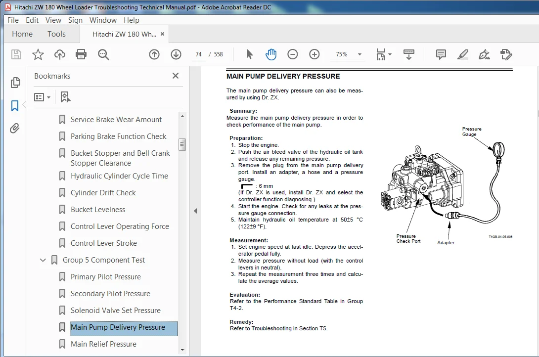
ZW180_TT4GD-E-00............................................................................................................  1
INTRODUCTION................................................................................................................  3
SAFETY......................................................................................................................  5
SECTION AND GROUP CONTENTS.................................................................................................. 35
SECTION 4 OPERATIONAL PERFORMANCE TEST...................................................................................... 37
	Group 1 Introduction.................................................................................................... 39
		Operational Performance Tests....................................................................................... 39
		Preparation for Performance Tests................................................................................... 40
	Group 2 Standard........................................................................................................ 41
		Operational Performance Standard Table.............................................................................. 41
		Main Pump P-Q Curve................................................................................................. 47
		Sensor Activating Range............................................................................................. 49
	Group 3 Engine Test..................................................................................................... 51
		Engine Speed........................................................................................................ 51
		Lubricant Consumption............................................................................................... 53
	Group 4 Wheel Loader Test............................................................................................... 55
		Travel Speed........................................................................................................ 55
		Service Brake Function Check........................................................................................ 56
		Service Brake Wear Amount........................................................................................... 57
		Parking Brake Function Check........................................................................................ 58
		Bucket Stopper and Bell Crank Stopper Clearance..................................................................... 60
		Hydraulic Cylinder Cycle Time....................................................................................... 62
		Cylinder Drift Check................................................................................................ 64
		Bucket Levelness.................................................................................................... 65
		Control Lever Operating Force....................................................................................... 66
		Control Lever Stroke................................................................................................ 67
	Group 5 Component Test.................................................................................................. 69
		Primary Pilot Pressure.............................................................................................. 69
		Secondary Pilot Pressure............................................................................................ 71
		Solenoid Valve Set Pressure......................................................................................... 72
		Main Pump Delivery Pressure......................................................................................... 74
		Main Relief Pressure................................................................................................ 76
		Steering Relief Pressure............................................................................................ 78
		Overload Relief Pressure............................................................................................ 80
		Main Pump Flow Rate................................................................................................. 82
		Regulator Adjustment................................................................................................ 86
		Service Brake Pressure (Front and Rear)............................................................................. 88
		Parking Brake Pressure.............................................................................................. 90
		Brake Accumulated Pressure.......................................................................................... 92
		Service Brake Warning Set Pressure (Decrease)....................................................................... 94
		Service Brake Warning Set Pressure (Increase)....................................................................... 96
		Transmission Clutch Pressure........................................................................................ 98
		Torque Converter Pressure (Inlet and Outlet)........................................................................ 99
	Group 6 Adjustment......................................................................................................101
		Transmission Learning...............................................................................................101
		Lift Arm Angle Sensor Learning (Optional)...........................................................................106
		Drive Belt Tension Adjustment.......................................................................................108
SECTION 5 TROUBLESHOOTING...................................................................................................111
	Group 1 Diagnosing Procedure............................................................................................115
		Introduction........................................................................................................115
		Diagnosing Procedure................................................................................................116
		How to Operate Service Mode of Monitor..............................................................................120
		Display List of Monitor Service Mode................................................................................121
	Group 2 Dr.ZX...........................................................................................................123
		Outline.............................................................................................................123
		Operation...........................................................................................................124
		Self-Diagnostic Result..............................................................................................126
		Select Controller...................................................................................................128
		Main Controller.....................................................................................................129
		Main Menu Monitor Display...........................................................................................130
		Setting.............................................................................................................134
		Record Data Display.................................................................................................141
		Password Change.....................................................................................................142
		Engine Controller...................................................................................................143
		Monitor Display.....................................................................................................144
		Recorded Data Display...............................................................................................148
		Password Change.....................................................................................................149
		ICF Controller......................................................................................................151
		Information C/U Various Setup.......................................................................................152
		Save Data Check.....................................................................................................162
		Password Change.....................................................................................................163
		Monitor Unit........................................................................................................165
		Monitoring..........................................................................................................166
		Various Settings....................................................................................................168
		Internal Hour Meter Synchronization.................................................................................169
		Password Change.....................................................................................................170
	Group 3 e-Wheel.........................................................................................................171
		Outline.............................................................................................................171
		List of Daily Report Data...........................................................................................172
		List of Frequency Distribution Data.................................................................................173
		List of Total Operationg Hours......................................................................................174
		List of Alarm.......................................................................................................175
		List of failure.....................................................................................................176
		How to Download and Upload Data of ICF..............................................................................177
		Various Setup of ICF and Satellite Communication Terminal by Using Dr.ZX............................................180
		List of ICF Fault Code..............................................................................................192
		List of Fault Code of Sattellite Communication Terminal.............................................................193
	Group 4 Component Layout................................................................................................197
		Main Component (Overview)...........................................................................................197
		Main Component (Upperstructure).....................................................................................198
		Main Component (Travel System)......................................................................................199
		Electric System (Overview)..........................................................................................200
		Electrical System (Cab).............................................................................................201
		Engine and Fan Pump.................................................................................................206
		Pump Device.........................................................................................................207
		Drive Unit..........................................................................................................207
		Control Valve.......................................................................................................208
		Ride Control Valve..................................................................................................209
		Charging Block......................................................................................................209
		Fan Motor...........................................................................................................209
		Steering Valve......................................................................................................210
		Emergency Steering Pump (Optional)..................................................................................210
		Components in Control Valve.........................................................................................212
		Components in Steering Valve........................................................................................218
		Components in Charging Block........................................................................................222
		Components in Ride Control Valve....................................................................................228
		Front View of Transmission..........................................................................................232
		Side View of Transmission...........................................................................................233
		Rear View of Transmission...........................................................................................234
		Cross-Sectional Drawing of Torque Converter.........................................................................235
		Cross-Sectional Drawing of Transmission.............................................................................236
		Cross-Sectional Drawing of Clutch Shaft.............................................................................237
		Cross-Sectional Drawing of Transmission Regulator Valve.............................................................238
		Cross-Sectional Drawing of Transmission Control Valve...............................................................239
	Group 5 Troubleshooting A...............................................................................................241
		Troubleshooting A Procedure.........................................................................................241
		MC Fault Code List..................................................................................................242
		ECM Fault Code List.................................................................................................262
		ICF Fault Code List.................................................................................................278
		Satellite Terminal Fault Code List..................................................................................280
		Monitor Unit Fault Code List........................................................................................282
		Controller Hardware Failure MC Fault Codes 11000 to 11002...........................................................283
		MC Fault Code 11003.................................................................................................284
		MC Fault Code 11004.................................................................................................285
		CAN Harness Check...................................................................................................286
		Engine Failure MC Fault Code 11103..................................................................................306
		MC Fault Code 11105.................................................................................................307
		Pump Failure MC Fault Code 11204....................................................................................308
		Pilot Failure MC Fault Code 11312...................................................................................309
		MC Fault Code 11313.................................................................................................310
		Proportional Solenoid Valve Failure MC Fault Code 11412.............................................................311
		MC Fault Code 11413.................................................................................................312
		MC Fault Code 11414, 11415, 11416, 11417, 11418, 11419..............................................................313
		Transmission Failure MC Fault Code 11600............................................................................316
		MC Fault Code 11601.................................................................................................317
		MC Fault Code 11602.................................................................................................318
		MC Fault Code 11904.................................................................................................319
		MC Fault Code 11905.................................................................................................320
		CAN Data Reception Failure MC Fault Codes 11910, 11920..............................................................321
		CAN Harness Check (MC Fault Codes 11910, 11920).....................................................................322
		MC Fault Code 11914.................................................................................................325
		CAN Harness Check Fault Code 11914..................................................................................326
		Other Failures MC Fault Code 11901..................................................................................329
		Proportional Solenoid Valve Truble Check............................................................................330
		ECM, Fault Code Contrast List.......................................................................................333
		ICF, Satellite Terminal Fault Codes 14000to14003....................................................................349
		ICF, Satellite Terminal Fault Codes 14006, 14008, 14100 to 14106....................................................353
		Monitor Unit Fault Codes 13306, 13308...............................................................................355
		Monitor Unit Fault Code 13312.......................................................................................356
		Monitor Unit Fault Code 13314.......................................................................................357
	Group 6 Troubleshooting B...............................................................................................359
		Troubleshooting B Procedure.........................................................................................359
		Relationship between Machine Trouble Symptoms and Related Parts.....................................................360
		Correlation between Trouble Symptoms and Part Failures..............................................................376
		Engine System Troubleshooting.......................................................................................390
		Front Attachment System Troubleshooting.............................................................................399
		Travel System Troubleshooting.......................................................................................418
		Brake System Troubleshooting........................................................................................434
		Steering System Troubleshooting.....................................................................................442
		Other System Troubleshooting........................................................................................445
		Exchange Inspection.................................................................................................467
		Bleeding Air from Brake (Axle)......................................................................................469
		One Part of Data, “Daily Report Data”, “Distribution Data”, “Total Operationg Hours” and “Alarm” is Not Recorded....470
	Group 7 Troubleshooting C...............................................................................................485
		Troubleshooting C (Trouble Shooting for Monitor) Procedure..........................................................485
		Malfunction of Indicator Light Check System.........................................................................486
		Malfunction of Buzzer in Monitor....................................................................................488
		Malfunction of Coolant Temperature Gauge............................................................................490
		Malfunction of Transmission Oil Temperature Gauge...................................................................492
		Malfunction of Fuel Gauge...........................................................................................494
		Malfunction of Turn Signal Indicators (Left and Right)..............................................................496
		Malfunction of Hazard Light Indicator...............................................................................497
		Malfunction of High Beam Indicator..................................................................................498
		Malfunction of Working Light Indicator..............................................................................500
		Malfunction of FNR Switch Indicator.................................................................................502
		Malfunction of Maintenance Indicator................................................................................504
		Malfunction of Preheat Indicator....................................................................................505
		Malfunction of Transmission Oil Temperature Indicator...............................................................506
		Malfunction of Hydraulic Oil Temperature Indicator..................................................................508
		Malfunction of Transmission Warning Indicator.......................................................................510
		Malfunction of Air Filter Restriction Indicator.....................................................................512
		Malfunction of Engine Oil Pressure Indicator........................................................................514
		Faulty Overheat Indicator...........................................................................................516
		Malfunction of Engine Warning Indicator.............................................................................518
		Malfunction of Stop Indicator.......................................................................................519
		Malfunction of Service Indicator....................................................................................520
		Malfunction of Parking Brake Indicator..............................................................................522
		Malfunction of Clearance Light Indicator............................................................................524
		Malfunction of Brake Low Oil Pressure Indicator.....................................................................525
		Malfunction of Brake Low Oil Level Indicator........................................................................526
		Malfunction of Emergency Steering Indicator (Optional)..............................................................528
		Malfunction of Low Steering Oil Pressure Indicator (Optional).......................................................530
		Malfunction of Discharge Warning Indicator..........................................................................532
		Malfunction of Monitor Display......................................................................................534
		Malfunction of Ride Control Indicator...............................................................................535
		Malfunction of Engine Coolant Temperature Display...................................................................536
	Group 8 Electrical System Inspection....................................................................................537
		Precautions for Inspection and Maintenance..........................................................................537
		Instructions for Disconnecting Connectors...........................................................................539
		Fuse Inspection.....................................................................................................542
		Fusible Link Inspection.............................................................................................544
		Battery Voltage Check...............................................................................................545
		Alternator Check....................................................................................................546
		Continuity Check....................................................................................................548
		Voltage and Current Measurement.....................................................................................550
		Check by False Signal...............................................................................................553
SERVICE MANUAL REVISION REQUEST FORM........................................................................................557
THE ATTACHED DIAGRAM LIST...................................................................................................558
Please Note:
⦁ This is the same manual used by the DEALERSHIPS to SERVICE your vehicle.
⦁ The manual can be all yours – Once payment is complete, you will be taken to the download page from where you can download the manual. All in 2-5 minutes time!!
⦁ Need any other service / repair / parts manual, please feel free to contact us at heydownloadss @gmail.com . We may surprise you with a nice offer