Hitachi ZW220-6 Wheel Loader Workshop + Troubleshooting + Operational Principle + Electrical-Hydraulic Circuit Manual – PDF Download
Original price was: $90.00.$39.00Current price is: $39.00.
Hitachi ZW220-6 Wheel Loader Workshop + Troubleshooting + Operational Principle + Electrical-Hydraulic Circuit Manual
This Listing includes all of the manuals mentioned below:
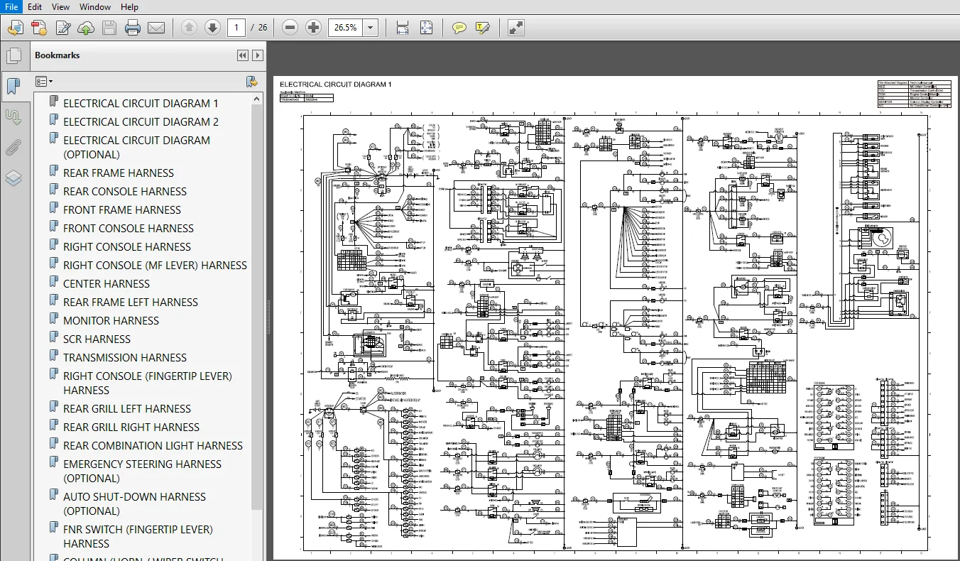
- ELECTRICAL CIRCUIT DIAGRAM.pdf
- ELECTRICAL-HYDRAULIC CIRCUIT DIAGRAM.pdf
- ELECTRICAL-HYDRAULIC CIRCUIT DIAGRAM-2.pdf
- ELECTRICAL-HYDRAULIC CIRCUIT DIAGRAM-3.pdf
- ELECTRICAL-HYDRAULIC CIRCUIT DIAGRAM-4.pdf
- ELECTRICAL-HYDRAULIC CIRCUIT DIAGRAM-5.pdf
- Hitachi ZW220-6 Wheel Loader Operational Principle Technical Manual.pdf
- Hitachi ZW220-6 Wheel Loader Troubleshooting Technical Manual.pdf
- Hitachi ZW220-6 Wheel Loader Workshop Manual.pdf
- OPERATIONAL PRINCIPLE-2.pdf
- OPERATIONAL PRINCIPLE-3.pdf
- TROUBLESHOOTING-2.pdf
Description
Hitachi ZW220-6 Wheel Loader Workshop + Troubleshooting + Operational Principle + Electrical-Hydraulic Circuit Manual
FILE DETAILS:
Hitachi ZW220-6 Wheel Loader Workshop + Troubleshooting + Operational Principle + Electrical-Hydraulic Circuit Manual
This Listing includes all of the manuals mentioned below:
- ELECTRICAL CIRCUIT DIAGRAM.pdf
- ELECTRICAL-HYDRAULIC CIRCUIT DIAGRAM.pdf
- ELECTRICAL-HYDRAULIC CIRCUIT DIAGRAM-2.pdf
- ELECTRICAL-HYDRAULIC CIRCUIT DIAGRAM-3.pdf
- ELECTRICAL-HYDRAULIC CIRCUIT DIAGRAM-4.pdf
- ELECTRICAL-HYDRAULIC CIRCUIT DIAGRAM-5.pdf
- Hitachi ZW220-6 Wheel Loader Operational Principle Technical Manual.pdf
- Hitachi ZW220-6 Wheel Loader Troubleshooting Technical Manual.pdf
- Hitachi ZW220-6 Wheel Loader Workshop Manual.pdf
- OPERATIONAL PRINCIPLE-2.pdf
- OPERATIONAL PRINCIPLE-3.pdf
- TROUBLESHOOTING-2.pdf
HITACHI ZW220-6 WHEEL LOADER WORKSHOP + TROUBLESHOOTING + OPERATIONAL PRINCIPLE + ELECTRICAL-HYDRAULIC CIRCUIT MANUAL – PDF DOWNLOAD:
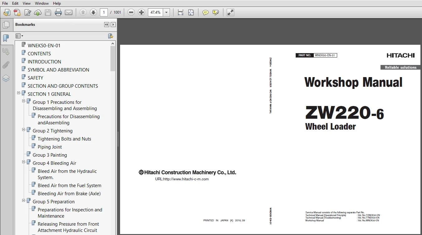
SCREENSHOTS OF THE MANUAL:
DESCRIPTION:
Hitachi ZW220-6 Wheel Loader Workshop + Troubleshooting + Operational Principle + Electrical-Hydraulic Circuit Manual
- This manual is written for an experienced technician to provide technical information needed to maintain and repair this machine.
- Be sure to thoroughly read this manual for correct product information and service procedures.
- If you have any questions or comments, at if you found any errors regarding the contents of this manual, please contact using “Service Manual Revision Request Form” at the end of this manual.
- This manual consists the Technical Manual and the Workshop Manual.
- Information included in the Technical Manual: technical information needed for redelivery and delivery, operation and activation of all devices and systems, operational performance tests, and troubleshooting procedures.
- Information included in the Workshop Manual: technical information needed for maintenance and repair of the machine, tools and devices needed for maintenance and repair, maintenance standards, and removal/installation and assemble/ disassemble procedures.
TABLE OF CONTENTS:
Hitachi ZW220-6 Wheel Loader Workshop Manual
Group 1 Precautions for Disassembling and Assembling
Precautions for Disassembling and
Assembling…………………………………………………………W1-1-1-1
Group 2 Tightening
Tightening Bolts and Nuts…………………………………….W1-2-1-1
Piping Joint……………………………………………………………..W1-2-1-4
Group 3 Painting
Group 4 Bleeding Air
Bleed Air from the Hydraulic System…………………..W1-4-1-1
Bleed Air from the Fuel System…………………………….W1-4-1-2
Bleeding Air from Brake (Axle)……………………………..W1-4-1-3
Group 5 Preparation
Preparations for Inspection and Maintenance…..W1-5-1-1
Releasing Pressure from Front Attachment
Hydraulic Circuit………………………………………………..W1-5-1-6
Releasing Pressure from Ride Control
Accumulator……………………………………………………….W1-5-1-7
Releasing Pressure from Parking Brake
Accumulator……………………………………………………….W1-5-1-8
Releasing Pressure from Hydraulic Oil Tank……….W1-5-1-9
Releasing Pressure from Expansion Tank…………W1-5-1-10
Group 1 Body
Center Hinge…………………………………………………………..W2-1-1-1
Group 2 Front Attachment
Pin and Bushing………………………………………………………W2-2-1-1
Standard Dimensions for Lift Arm and
Bucket………………………………………………………………….W2-2-2-1
Cylinder……………………………………………………………………W2-2-3-1
Group 1 Cab
Removal and Installation of Cab………………………….W3-1-1-1
Group 2 Counterweight
Removal and Installation of Counterweight………W3-2-1-1
Group 3 Center Hinge
Removal and Installation of Center Hinge………….W3-3-1-1
Group 4 Engine
Removal and Installation of Engine…………………….W3-4-1-1
Group 5 Radiator Assembly
Removal and Installation of Radiator
Assembly…………………………………………………………….W3-5-1-1
Group 6 Hydraulic Oil Tank
Removal and Installation of Hydraulic Oil
Tank……………………………………………………………………..W3-6-1-1
Group 7 Fuel Tank
Removal and Installation of Fuel Tank…………………W3-7-1-1
Group 8 Pump Device
Removal and Installation of Pump Device………….W3-8-1-1
Disassembly of Pump Device……………………………….W3-8-2-1
Assembly of Pump Device…………………………………….W3-8-2-3
Disassembly of Main Pump…………………………………..W3-8-3-1
Assembly of Main Pump………………………………………..W3-8-3-5
Disassembly of Regulator……………………………………..W3-8-4-1
Assembly of Regulator…………………………………………..W3-8-4-3
Disassembly of Priority Valve………………………………..W3-8-5-1
Assembly of Priority Valve…………………………………….W3-8-5-3
Structure of Pilot Pump…………………………………………W3-8-6-1
Group 9 Control Valve
Removal and Installation of Control Valve………….W3-9-1-1
Disassembly of Control Valve……………………………….W3-9-2-1
Disassembly of Control Valve……………………………….W3-9-2-4
Assembly of Control Valve…………………………………….W3-9-2-9
Assembly of Control Valve………………………………….W3-9-2-14
Group 10 Pilot Valve
Removal and Installation of Pilot Valve…………….W3-10-1-1
Removal and Installation of Pilot Valve (Two
Lever Type)……………………………………………………….W3-10-2-1
Disassembly of Pilot Valve………………………………….W3-10-3-1
Assembly of Pilot Valve……………………………………….W3-10-3-4
Disassembly of Pilot Valve (Two Lever Type)……W3-10-4-1
Assembly of Pilot Valve (Two Lever Type)………..W3-10-4-7
Group 11 Brake Charge Valve
Removal and Installation of Brake Charge
Valve………………………………………………………………….W3-11-1-1
Structure of Brake Charge Valve………………………..W3-11-2-1
Removal and Installation of Brake
Accumulator…………………………………………………….W3-11-3-1
Group 12 Manifold Valve
Removal and Installation of Manifold Valve…….W3-12-1-1
Disassembly of Manifold Valve………………………….W3-12-2-1
Assembly of Manifold Valve……………………………….W3-12-2-4
Group 13 Solenoid Valve
Removal and Installation of 2-Spool Solenoid
Valve Unit…………………………………………………………W3-13-1-1
Structure of 2-Spool Solenoid Valve Unit…………W3-13-2-1
Removal and Installation of Parking Brake
Solenoid Valve Unit…………………………………………W3-13-3-1
Structure of Parking Brake Solenoid Valve
Unit……………………………………………………………………W3-13-4-1
Structure of Parking Brake Solenoid Valve………W3-13-5-1
Group 14 Flow Regulator Valve
Removal and Installation of Flow Regulator
Valve………………………………………………………………….W3-14-1-1
Structure of Flow Regulator Valve…………………….W3-14-2-1
Group 15 Cooling Fan System
Removal and Installation of Fan Valve………………W3-15-1-1
Structure of Fan Valve………………………………………….W3-15-2-1
Removal and Installation of Fan Motor…………….W3-15-3-1
Structure of Fan Motor………………………………………..W3-15-4-1
Removal and Installation of Fan Pump…………….W3-15-5-1
Disassembly of Fan Pump…………………………………..W3-15-6-1
Assembly of Fan Pump……………………………………….W3-15-6-3
Group 16 Ride Control Accumulator
Removal and Installation of Ride Control
Accumulator…………………………………………………….W3-16-1-1
Group 17 Battery Disconnect Switch
Removal and Installation of Battery
Disconnect Switch………………………………………….W3-17-1-1
Group 18 Aftertreatment Device
Removal and Installation of Aftertreatment
Device……………………………………………………………….W3-18-1-1
Group 19 DEF Tank
Removal and Installation of DEF Tank………………W3-19-1-1
Group 20 Coolant Control Valve
Removal and Installation of Coolant Control
Valve………………………………………………………………….W3-20-1-1
Group 21 DEF Supply Module
Removal and Installation of DEF Supply
Module……………………………………………………………..W3-21-1-1
Group 22 Exterior Components
Removal and Installation of Exterior
Components……………………………………………………W3-22-1-1
Group 1 Tire
Removal and Installation of Front Tire………………..W4-1-1-1
Removal and Installation of Rear Tire………………….W4-1-2-1
Group 2 Drive Unit
Removal and Installation of Drive Unit……………….W4-2-1-1
Disassembly and Assembly of Drive Unit……………W4-2-2-1
Removal and Installation of Torque Converter….W4-2-3-1
Disassembly and Assembly of Transmission ……..W4-2-4-1
Disassembly and Assembly of Transmission
Control Valve ……………………………………………………..W4-2-5-1
Removal and installation of parking brake
(Replace the brake friction pad)………………………W4-2-6-1
Group 3 Axle
Removal and Installation of Front Axle……………….W4-3-1-1
Removal and Installation of Rear Axle…………………W4-3-2-1
Disassembly of Axle……………………………………………….W4-3-3-1
Assembly of Axle………………………………………………….W4-3-3-18
Group 4 Propeller Shaft
Removal and Installation of Propeller Shaft……….W4-4-1-1
Group 5 Brake Valve
Removal and Installation of Brake Valve……………..W4-5-1-1
Disassembly of Brake Valve…………………………………..W4-5-2-1
Disassembly of Brake Valve…………………………………..W4-5-2-2
Assembly of Brake Valve………………………………………..W4-5-2-3
Assembly of Brake Valve………………………………………..W4-5-2-4
Group 6 Steering Device
Removal and Installation of Steering Pilot
Valve…………………………………………………………………….W4-6-1-1
Disassembly of Steering Pilot Valve …………………..W4-6-2-1
Assembly of Steering Pilot Valve………………………….W4-6-2-4
Removal and Installation of Steering Valve
(Without Emergency Steering)………………………..W4-6-3-1
Removal and Installation of Steering Valve
(With Emergency Steering)………………………………W4-6-4-1
Disassembly of Steering Valve……………………………..W4-6-5-1
Assembly of Steering Valve…………………………………..W4-6-5-4
Disassembly of Emergency Steering Check
Block…………………………………………………………………….W4-6-6-1
Assembly of Emergency Steering Check Block….W4-6-6-3
Removal and Installation of Steering Cylinder…..W4-6-7-1
Disassembly of Steering Cylinder………………………..W4-6-8-1
Assembly of Steering Cylinder……………………………..W4-6-8-5
Removal and Installation of Left Stop Valve……….W4-6-9-1
Removal and Installation of Right Stop Valve….W4-6-10-1
Disassembly of Stop Valve………………………………….W4-6-11-1
Assembly of Stop Valve……………………………………….W4-6-11-2
Group 7 Emergency Steering Device
Removal and Installation of Emergency
Steering Pump……………………………………………………W4-7-1-1
Group 1 Front Attachment
Removal and Installation of Front Attachment….W5-1-1-1
Removal and Installation of Bell Crank……………….W5-1-2-1
Removal and Installation of Bucket……………………..W5-1-3-1
Removal and Installation of Bushing…………………..W5-1-4-1
Group 2 Cylinder
Removal and Installation of Lift Arm Cylinder……W5-2-1-1
Removal and Installation of Bucket Cylinder……..W5-2-2-1
Disassembly of Lift Arm Cylinder and Bucket
Cylinder……………………………………………………………….W5-2-3-1
Assembly of Lift Arm Cylinder and Bucket
Cylinder……………………………………………………………….W5-2-3-5
Hitachi ZW220-6 Wheel Loader Troubleshooting Manual
SECTION 4 OPERATIONAL
PERFORMANCE TEST
Group 1 Introduction
Group 2 Standard
Group 3 Engine Test
Group 4 Machine Performance Test
Group 5 Component Test
Group 6 Adjustment
SECTION 5 TROUBLESHOOTING
Group 1 Diagnosing Procedure
Group 2 Monitor
Group 3 e-Service
Group 4 Component Layout
Group 5 Troubleshooting A
Group 6 Troubleshooting B
Group 7 Air Conditioner
Hitachi ZW220-6 Wheel Loader Operational Principle Manual
Group 1 Specifications
Specifications………………………………………………………………T1-1-1
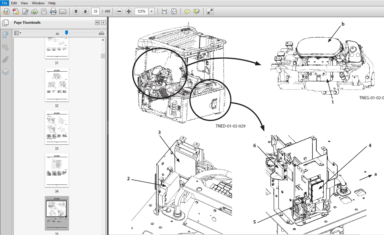
Group 2 Component Layout
Main Component (Overview)……………………………………T1-2-1
Main Component………………………………………………………..T1-2-3
Electrical System (Overview)…………………………………….T1-2-5
Air Cleaner and Radiator Assembly………………………….T1-2-6
Battery Box…………………………………………………………………..T1-2-8
Hydraulic Oil Tank……………………………………………………….T1-2-9
Fuel Tank…………………………………………………………………….T1-2-10
Drive Unit……………………………………………………………………T1-2-11
Front Axle……………………………………………………………………T1-2-12
Cab………………………………………………………………………………T1-2-13
Engine…………………………………………………………………………T1-2-19
Aftertreatment Device……………………………………………..T1-2-20
Fan Valve…………………………………………………………………….T1-2-21
Pump Device……………………………………………………………..T1-2-22
Control Valve……………………………………………………………..T1-2-22
Manifold Valve……………………………………………………………T1-2-23
Parking Brake Solenoid Valve………………………………….T1-2-23
Brake Charge Valve……………………………………………………T1-2-23
2-Spool Solenoid Valve Unit…………………………………….T1-2-23
Emergency Steering Block……………………………………….T1-2-24
Emergency Steering Pump……………………………………..T1-2-24
Flow Regulator Valve………………………………………………..T1-2-24
DEF Tank……………………………………………………………………..T1-2-25
DEF Supply Module…………………………………………………..T1-2-25
Group 3 Component Specifications
Engine…………………………………………………………………………..T1-3-1
Engine Accessories……………………………………………………..T1-3-5
Hydraulic Component………………………………………………..T1-3-6
Electrical Component……………………………………………….T1-3-12
Group 1 Controller
Outline………………………………………………………………………….T2-1-1
CAN Circuit…………………………………………………………………..T2-1-2
Group 2 Control System
Outline………………………………………………………………………….T2-2-1
Engine Control (ECM)…………………………………………………T2-2-4
Pump Control…………………………………………………………….T2-2-37
Transmission Control (TCU)……………………………………..T2-2-42
Forward/Reverse Lever Priority Control (Option)…T2-2-46
Fan Control, Valve Control……………………………………….T2-2-61
Control by Electrical and Hydraulic Combined
Circuit……………………………………………………………………..T2-2-93
Group 3 Engine System
Outline………………………………………………………………………….T2-3-1
ECM System…………………………………………………………………T2-3-2
Fuel Injection Control…………………………………………………T2-3-4
Fuel Injection Amount Correction Control……………T2-3-12
EGR Control………………………………………………………………..T2-3-14
Preheating Control……………………………………………………T2-3-16
Variable Turbocharger Control………………………………..T2-3-17
Alarm Control…………………………………………………………….T2-3-18
Urea SCR System……………………………………………………….T2-3-19
Engine Output Restriction Control
(INDUCEMENT)……………………………………………………..T2-3-30
Aftertreatment Device……………………………………………..T2-3-36
Aftertreatment Device Regeneration Control………T2-3-38
Group 4 Hydraulic System
Outline………………………………………………………………………….T2-4-1
Pilot Circuit…………………………………………………………………..T2-4-2
Parallel Circuit Flow Rate Control……………………………T2-4-32
Main Circuit………………………………………………………………..T2-4-34
Fan Circuit…………………………………………………………………..T2-4-48
Emergency Steering Circuit (Option)……………………..T2-4-50
Group 5 Electrical System
Outline………………………………………………………………………….T2-5-1
Main Circuit………………………………………………………………….T2-5-2
Electric Power Circuit (Key Switch: OFF)………………….T2-5-4
CAN Circuit…………………………………………………………………..T2-5-6
Accessory Circuit (Key Switch: ACC)…………………………T2-5-8
Starting Circuit (Key Switch: START)……………………….T2-5-10
Charging Circuit (Key Switch: ON)………………………….T2-5-12
Surge Voltage Prevention Circuit……………………………T2-5-16
Pilot Shut-Off Circuit (Key Switch: ON)…………………..T2-5-18
Auto Shut-Down Circuit (Option)…………………………..T2-5-20
Engine Stop Circuit……………………………………………………T2-5-22
Air Conditioner Circuit……………………………………………..T2-5-24
Steering Column Box Circuit……………………………………T2-5-27
Headlight Circuit……………………………………………………….T2-5-28
Hazard Light Circuit (Key Switch: OFF)…………………..T2-5-34
Turn Signal Light Circuit…………………………………………..T2-5-36
Horn Circuit (Key Switch: OFF)………………………………..T2-5-38
Back Buzzer Circuit……………………………………………………T2-5-40
Brake Light Circuit…………………………………………………….T2-5-42
Parking Brake Circuit…………………………………………………T2-5-44
Accessory Circuit……………………………………………………….T2-5-49
Work Light Circuit……………………………………………………..T2-5-50
Wiper Circuit………………………………………………………………T2-5-52
Cab Light Circuit………………………………………………………..T2-5-58
Group 1 Pump Device
Outline………………………………………………………………………….T3-1-1
Main Pump…………………………………………………………………..T3-1-2
Regulator……………………………………………………………………..T3-1-4
Priority Valve………………………………………………………………T3-1-18
Steering Main Relief Valve……………………………………….T3-1-19
Pilot Pump………………………………………………………………….T3-1-20
Pump Delivery Pressure Sensor………………………………T3-1-20
Group 2 Control Valve
Outline………………………………………………………………………….T3-2-1
Hydraulic Circuit………………………………………………………….T3-2-6
Main Relief Valve……………………………………………………….T3-2-12
Overload Relief Valve (with Make-Up Function)…..T3-2-14
Anti-Drift Valve…………………………………………………………..T3-2-18
Lift Arm Flow Rate Control Valve…………………………….T3-2-22
Charge-Cut Valve in Ride Control Spool ……………….T3-2-26
Drain Plug…………………………………………………………………..T3-2-30
Pump Flow Rate Control Valve ……………………………….T3-2-32
Group 3 Cooling Fan System
Fan Pump……………………………………………………………………..T3-3-1
Fan Motor…………………………………………………………………….T3-3-2
Fan Valve (with Fan Reverse Rotation) (Optional)….T3-3-3
Group 4 Steering Pilot Valve
Outline………………………………………………………………………….T3-4-1
Structure………………………………………………………………………T3-4-2
Operation……………………………………………………………………..T3-4-3
Group 5 Steering Valve
Outline………………………………………………………………………….T3-5-1
Operation……………………………………………………………………..T3-5-4
Steering Overload Relief Valve………………………………….T3-5-6
Group 6 Pilot Valve
Outline (Fingertip Control Type Pilot Valve for
Front Attachment)…………………………………………………T3-6-1
Operation……………………………………………………………………..T3-6-2
Electromagnetic Detent…………………………………………….T3-6-6
Outline (Joystick Type Pilot Valve for Front
Attachment)……………………………………………………………T3-6-7
Operation……………………………………………………………………..T3-6-9
Electromagnetic Detent…………………………………………..T3-6-16
Group 7 Brake Charge Valve / Manifold Valve
Outline………………………………………………………………………….T3-7-1
Brake Charge Valve……………………………………………………..T3-7-2
Manifold Valve……………………………………………………………..T3-7-7
Pilot Relief Valve………………………………………………………….T3-7-8
Torque Control Solenoid Valve………………………………….T3-7-9
Control Lever Lock Solenoid Valve…………………………T3-7-11
Service Brake Accumulator …………………………………….T3-7-12
Pilot Accumulator……………………………………………………..T3-7-13
Group 8 Drive Unit
Outline………………………………………………………………………….T3-8-1
Torque Converter………………………………………………………..T3-8-6
Transmission………………………………………………………………..T3-8-8
Operation of Transmission……………………………………….T3-8-10
Transmission Control Valve……………………………………..T3-8-26
Drive Unit Circuit……………………………………………………….T3-8-28
Group 9 Axle
Outline………………………………………………………………………….T3-9-1
Differential……………………………………………………………………T3-9-2
Torque Proportioning Differential (TPD)…………………T3-9-6
Limited Slip Differential (LSD) (Optional)………………..T3-9-8
Service Brake……………………………………………………………..T3-9-10
Final Drive / Axle Shaft……………………………………………..T3-9-12
Group 10 Brake Valve
Outline………………………………………………………………………..T3-10-1
Operation……………………………………………………………………T3-10-4
Group 11 Others
Propeller Shaft…………………………………………………………..T3-11-1
2-Spool Solenoid Valve Unit…………………………………….T3-11-3
Parking Brake Solenoid Valve Unit………………………….T3-11-5
Parking Brake Solenoid Valve………………………………….T3-11-6
Parking Brake Accumulator……………………………………..T3-11-8
Flow Regulator Valve………………………………………………..T3-11-9
Steering Accumulator……………………………………………T3-11-12
Ride Control Accumulator (Option)…………………….T3-11-12
Torque Converter Cooler Check Valve…………………T3-11-13
Stop Valve………………………………………………………………..T3-11-14
Pilot Oil Filter…………………………………………………………..T3-11-16
Emergency Steering Check Block (Option)………..T3-11-17
Emergency Steering Pump (Option)……………………T3-11-18
PLEASE NOTE:
- This is the same manual used by the dealers to diagnose and troubleshoot your vehicle
- You will be directed to the download page as soon as the purchase is completed. The whole payment and downloading process will take anywhere between 2-5 minutes
- Need any other service / repair / parts manual, please feel free to contact [email protected] . We still have 50,000 manuals unlisted