Hitachi ZW250-6 Wheel Loader Workshop Manual (WNEM50-EN-01) – PDF Download
Original price was: $90.95.$24.95Current price is: $24.95.
- Hitachi ZW250-6 Wheel Loader Workshop Manual
- Part No:WNEM50-EN-01
Description
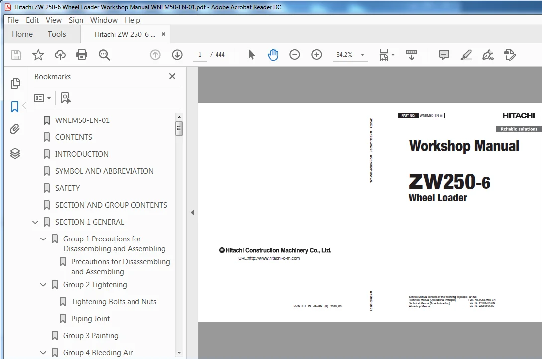
Hitachi ZW250-6 Wheel Loader Workshop Manual (WNEM50-EN-01)
File Details:
Hitachi ZW250-6 Wheel Loader Workshop Manual (WNEM50-EN-01)
- Manual Language:English
- Pages: 444
- Size: 38.2 MB
- Downloadable:Yes
- Format:PDF
HITACHI ZW250-6 WHEEL LOADER WORKSHOP MANUAL (WNEM50-EN-01) – PDF DOWNLOAD:
Image Preview:
Description:
Hitachi ZW250-6 Wheel Loader Workshop Manual (WNEM50-EN-01)
To The Reader
This manual is written for an experienced technician to provide technical information needed to maintain and repair this machine.
The machine specification and description according to destination may be explained on this manual.
Be sure to thoroughly read this manual for correct product information and service procedures.
If you have any questions or comments, at if you found any errors regarding the contents of this manual, please contact using “Service Manual Revision Request Form” at the end of this manual.
Additional References
Please refer to the other materials (operator’s manual, parts catalog, engine technical material and Hitachi training material etc.) in addition to this manual.
Manual Composition
This manual consists the Technical Manual, the Workshop Manual and the Engine Manual.
Information included in the Technical Manual: Technical information needed for redelivery and delivery, operation and activation of all devices and systems, operational performance tests, and troubleshooting procedures.
Information included in the Workshop Manual: Technical information needed for maintenance and repair of the machine, tools and devices needed for maintenance and repair, maintenance standards, and removal / installation and assemble / disassemble procedures.
Information included in the Engine Manual: Technical information needed for redelivery and delivery and maintenance and repair of the machine, operation and activation of all devices and systems, troubleshooting and assemble / disassemble procedures.
Table Of Contents:
Hitachi ZW250-6 Wheel Loader Workshop Manual (WNEM50-EN-01)
WNEM50-EN-01..........................................................................  1
CONTENTS..............................................................................  3
INTRODUCTION.......................................................................... 13
SYMBOL AND ABBREVIATION............................................................... 15
SAFETY................................................................................ 17
SECTION AND GROUP CONTENTS............................................................ 55
SECTION 1 GENERAL..................................................................... 59
	Group 1 Precautions for Disassembling and Assembling.............................. 61
		Precautions for Disassembling and Assembling.................................. 61
	Group 2 Tightening................................................................ 67
		Tightening Bolts and Nuts..................................................... 67
		Piping Joint.................................................................. 70
	Group 3 Painting.................................................................. 77
	Group 4 Bleeding Air.............................................................. 85
		Bleed Air from the Hydraulic System........................................... 85
		Bleed Air from the Fuel System................................................ 86
		Bleeding Air from Brake (Axle)................................................ 87
	Group 5 Preparation............................................................... 89
		Preparations for Inspection and Maintenance................................... 89
		Releasing Pressure from Front Attachment Hydraulic Circuit.................... 94
		Releasing Pressure from Ride Control Accumulator.............................. 95
		Releasing Pressure from Parking Brake Accumulator............................. 96
		Releasing Pressure from Hydraulic Oil Tank.................................... 97
		Releasing Pressure from Reserve Tank.......................................... 98
SECTION 2 MAINTENANCE STANDARD........................................................101
	Group 1 Body......................................................................103
		Center Hinge..................................................................103
		Pilot Valve (Two Lever Type)..................................................105
	Group 2 Front Attachment..........................................................107
		Pin and Bushing...............................................................107
		Standard Dimensions for Lift Arm and Bucket...................................109
		Bucket Stopper Clearance......................................................110
		Cylinder......................................................................111
SECTION 3 BODY........................................................................115
	Group 1 Cab.......................................................................117
		Removal and Installation of Cab...............................................117
	Group 2 Counterweight.............................................................149
		Removal and Installation of Counterweight.....................................149
	Group 3 Center Hinge..............................................................153
		Removal and Installation of Center Hinge......................................153
	Group 4 Engine....................................................................179
		Removal and Installation of Engine............................................179
	Group 5 Radiator Assembly.........................................................219
		Removal and Installation of Radiator Assembly.................................219
	Group 6 Hydraulic Oil Tank........................................................237
		Removal and Installation of Hydraulic OilTank.................................237
	Group 7 Fuel Tank.................................................................247
		Removal and Installation of Fuel Tank.........................................247
	Group 8 Pump Device...............................................................259
		Removal and Installation of Pump Device.......................................259
		Disassembly of Pump Device....................................................269
		Assembly of Pump Device.......................................................271
		Disassembly of Main Pump......................................................273
		Assembly of Main Pump.........................................................277
		Disassembly of Regulator......................................................283
		Assembly of Regulator.........................................................285
		Disassembly of Priority Valve.................................................287
		Assembly of Priority Valve....................................................289
		Structure of Pilot Pump.......................................................291
	Group 9 Control Valve.............................................................293
		Removal and Installation of Control Valve.....................................293
		Disassembly of Control Valve..................................................303
		Assembly of Control Valve.....................................................310
	Group 10 Pilot Valve..............................................................319
		Removal and Installation of Pilot Valve (Single Lever Type)...................319
		Removal and Installation of Pilot Valve (Two Lever Type)......................327
		Disassembly of Pilot Valve (Single Lever Type)................................339
		Assembly of Pilot Valve (Single Lever Type)...................................342
		Disassembly of Pilot Valve (Two Lever Type)...................................347
		Assembly of Pilot Valve (Two Lever Type)......................................353
	Group 11 Brake Charge Valve.......................................................361
		Removal and Installation of Brake Charge Valve................................361
		Structure of Brake Charge Valve...............................................369
		Removal and Installation of Brake Accumulator.................................371
	Group 12 Manifold Valve...........................................................377
		Removal and Installation of Manifold Valve....................................377
		Disassembly of Manifold Valve.................................................385
		Assembly of Manifold Valve....................................................388
	Group 13 Solenoid Valve...........................................................393
		Removal and Installation of 2-Spool Solenoid Valve Unit.......................393
		Structure of 2-Spool Solenoid Valve Unit......................................397
		Removal and Installation of Parking Brake Solenoid Valve Unit.................399
		Structure of Parking Brake Solenoid Valve Unit................................405
		Structure of Parking Brake Solenoid Valve.....................................407
	Group 14 Flow Regulator Valve.....................................................409
		Removal and Installation of Flow Regulator Valve..............................409
		Structure of Flow Regulator Valve.............................................413
	Group 15 Cooling Fan System.......................................................415
		Removal and Installation of Fan Valve.........................................415
		Structure of Fan Valve........................................................419
		Removal and Installation of Fan Motor.........................................421
		Structure of Fan Motor........................................................427
		Removal and Installation of Fan Pump..........................................429
		Disassembly of Fan Pump.......................................................435
		Assembly of Fan Pump..........................................................437
	Group 16 Ride Control Accumulator.................................................441
		Removal and Installation of Ride Control Accumulator..........................441
	Group 17 Battery Disconnect Switch................................................  0
		Removal and Installation of Battery Disconnect Switch.........................  0
	Group 18 Aftertreatment Device....................................................  0
		Removal and Installation of Aftertreatment Device.............................  0
	Group 19 DEF Tank.................................................................  0
		Removal and Installation of DEF Tank..........................................  0
	Group 20 Coolant Control Valve....................................................  0
		Removal and Installation of Coolant Control Valve.............................  0
	Group 21 DEF Supply Module........................................................  0
		Removal and Installation of DEF Supply Module.................................  0
	Group 22 Exterior Components......................................................  0
		Removal and Installation of Exterior Components...............................  0
SECTION 4 TRAVEL SYSTEM...............................................................  0
	Group 1 Tire......................................................................  0
		Removal and Installation of Front Tire........................................  0
		Removal and Installation of Rear Tire.........................................  0
	Group 2 Drive Unit................................................................  0
		Removal and Installation of Drive Unit........................................  0
		Disassembly and Assembly of Drive Unit........................................  0
		Removal and Installation of Torque Converter..................................  0
		Disassembly and Assembly of Transmission......................................  0
		Disassembly and Assembly of Transmission Control Valve........................  0
		Removal and installation of parking brake (Replace the brake friction pad)....  0
	Group 3 Axle......................................................................  0
		Removal and Installation of Front Axle........................................  0
		Removal and Installation of Rear Axle.........................................  0
		Disassembly of Axle...........................................................  0
		Assembly of Axle..............................................................  0
	Group 4 Propeller Shaft...........................................................  0
		Removal and Installation of Propeller Shaft...................................  0
	Group 5 Brake Valve...............................................................  0
		Removal and Installation of Brake Valve.......................................  0
		Disassembly of Brake Valve....................................................  0
		Disassembly of Brake Valve....................................................  0
		Assembly of Brake Valve.......................................................  0
		Assembly of Brake Valve.......................................................  0
	Group 6 Steering Device...........................................................  0
		Removal and Installation of Steering Pilot Valve..............................  0
		Disassembly of Steering Pilot Valve...........................................  0
		Assembly of Steering Pilot Valve..............................................  0
		Removal and Installation of Steering Valve (Without Secondary Steering).......  0
		Removal and Installation of Steering Valve (With Secondary Steering)..........  0
		Disassembly of Steering Valve.................................................  0
		Assembly of Steering Valve....................................................  0
		Disassembly of Secondary Steering Check Block.................................  0
		Assembly of Secondary Steering Check Block....................................  0
		Removal and Installation of Steering Cylinder.................................  0
		Disassembly of Steering Cylinder..............................................  0
		Assembly of Steering Cylinder.................................................  0
		Removal and Installation of Steering Accumulator..............................  0
		Removal and Installation of Left Stop Valve...................................  0
		Removal and Installation of Right Stop Valve..................................  0
		Disassembly of Stop Valve.....................................................  0
		Assembly of Stop Valve........................................................  0
	Group 7 Secondary Steering Device.................................................  0
		Removal and Installation of Secondary Steering Pump...........................  0
	Group 8 Joystick Steering.........................................................  0
		Removal and Installation of Joystick Steering Valve...........................  0
		Disassembly and Assembly of Joystick Steering Control Valve...................  0
		Disassembly and Assembly of Joystick Steering Solenoid Valve..................  0
		Removal and Installation of Joystick Steering Lever (for Grammer Seat)........  0
		Removal and Installation of Joystick Steering Lever (for Sears Seat)..........  0
SECTION 5 FRONT ATTACHMENT............................................................  0
	Group 1 Front Attachment..........................................................  0
		Removal and Installation of Front Attachment..................................  0
		Removal and Installation of Bell Crank........................................  0
		Removal and Installation of Bucket............................................  0
		Removal and Installation of Bushing...........................................  0
	Group 2 Cylinder..................................................................  0
		Removal and Installation of Lift Arm Cylinder.................................  0
		Removal and Installation of Bucket Cylinder...................................  0
		Disassembly of Lift Arm Cylinder and Bucket Cylinder..........................  0
		Assembly of Lift Arm Cylinder and Bucket Cylinder.............................  0
SERVICE MANUAL REVISION REQUEST FORM..................................................  0
Please Note:
⦁ This is the SAME MANUAL used by the dealerships to diagnose your vehicle
⦁ No waiting for couriers / posts as this is a PDF manual and you can download it within 2 minutes time once you make the payment.
⦁ Your payment is all safe and the delivery of the manual is INSTANT – You will be taken to the DOWNLOAD PAGE.
⦁ So have no hesitations whatsoever and write to us about any queries you may have : heydownloadss @gmail.com