Trusted Business
Verified & Licensed
Virus Free Files
100% Safe Downloads
Secure Payment
SSL Protected
Instant Delivery
Available Immediately
Sale!

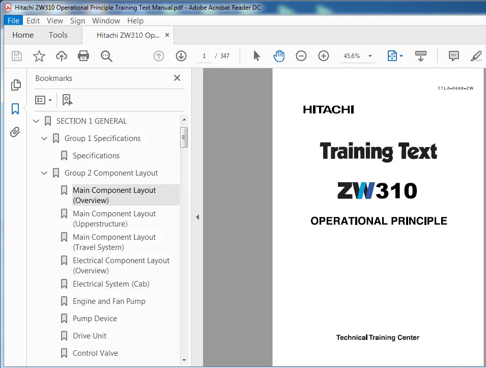
Hitachi ZW310 Operational Principle Training Text Manual (TTLA-0668-ZW) – PDF Download
Original price was: $89.95.$23.95Current price is: $23.95.
- Hitachi ZW310 Operational Principle Training Text Manual
- Part No:TTLA-0668-ZW
Instant PDF Download
Available immediately
Save to Your Device
Download & keep forever
Antivirus Scanned
100% virus-free
Trusted Worldwide
175,000+ customers
Description
Hitachi ZW310 Operational Principle Training Text Manual (TTLA-0668-ZW)
File Details:
Hitachi ZW310 Operational Principle Training Text Manual (TTLA-0668-ZW)
- Manual Language:English
- Pages: 347
- Size: 17.5 MB
- Downloadable:Yes
- Format:PDF
HITACHI ZW310 OPERATIONAL PRINCIPLE TRAINING TEXT MANUAL (TTLA-0668-ZW) – PDF DOWNLOAD:
Image Preview:
Description:
Hitachi ZW310 Operational Principle Training Text Manual (TTLA-0668-ZW)
- There are four controllers as shown below with MC – Main Controller – installed at their center.
• MC: Main Controller
• ICF: Information Controller
• ECM: Engine Control Module
• Monitor Unit - Controllers are mutually connected through CAN, and each controller uploads analog signals detected by sensors and switches as well as analog output signals to solenoid valves on the CAN by converting them into digital ones.
- As the signals are processed into the digital ones, a large amount of signals detected at each controller can be transmitted through few wires in a short time.
- MC, ECM, and monitor unit display indications on monitors and make various controls of the vehicle body by using analog signals received by each controller as well as digital signals detected on the CAN.
- ICF stores machine history, receives digital signals for various adjustments from Dr-ZX, transmits them to the CAN, and transmits the vehicle body signal (digital signal) received by each controller to Dr-ZX. A GPS-provision (optional) vehicle makes location arithmetic operation, utilising signals received by artificial sattelites, and transmits body information to the e-service host computer through artificial satellites. (Refer to the TROUBLESHOOTING/ICF)
Table Of Contents:
Hitachi ZW310 Operational Principle Training Text Manual (TTLA-0668-ZW)
MATERIALS TOP.....................................................................  0
OPERATIONAL PRONCIPLE.............................................................  1
SECTION 1 GENERAL.................................................................  2
	Group 1 Specifications........................................................  4
		Specifications............................................................  4
	Group 2 Component Layout......................................................  6
		Main Component Layout (Overview)..........................................  6
		Main Component Layout (Upperstructure)....................................  7
		Main Component Layout (Travel System).....................................  8
		Electrical Component Layout (Overview)....................................  9
		Electrical System (Cab)................................................... 10
		Engine and Fan Pump....................................................... 15
		Pump Device............................................................... 16
		Drive Unit................................................................ 16
		Control Valve............................................................. 17
		Ride Control Valve, (Optional)............................................ 18
		Charging Block............................................................ 18
		Fan Motor................................................................. 18
		Steering Valve............................................................ 19
		Emergency Steering Pump................................................... 19
	Group 3 Component Specifications.............................................. 20
		Engine.................................................................... 20
		Engine Accessories........................................................ 25
		Hydraulic Component....................................................... 26
		Electrical Component......................................................  0
SECTION 2 SYSTEM.................................................................. 32
	Group 1 Control System........................................................ 34
		Outline................................................................... 34
		Engine Control............................................................ 39
		Pump Control.............................................................. 48
		Transmission Control...................................................... 53
		Other Controls............................................................ 74
		Control by Electric and Hydraulic Combined Circuit........................ 84
	Group 2 ECM System............................................................ 98
		Outline................................................................... 98
		Fuel Injection Control.................................................... 99
	Group 3 Hydraulic System......................................................104
		Outline...................................................................104
		Main Circuit..............................................................105
		Pilot Circuit.............................................................116
		Steering Circuit..........................................................129
		Hydraulic Drive Fan Circuit...............................................135
	Group 4 Electrical System.....................................................138
		Outline...................................................................138
		Main Circuit..............................................................139
		Electric Power Circuit....................................................140
		Indicator Light Check Circuit.............................................141
		Accessory Circuit.........................................................142
		Preheat Circuit...........................................................143
		Starting Circuit..........................................................145
		Charging Circuit..........................................................149
		Serge Voltage Prevention Circuit..........................................151
		Engine Stop Circuit.......................................................153
		Lamplight Circait.........................................................154
		Head Light Circuit........................................................155
		Turn Signal Circuit.......................................................159
		Brake Light Circuit.......................................................160
		Hazard Light Circuit......................................................161
		Horn Circuit..............................................................162
		Reverse Light/Buzzer Circuit..............................................163
		Parking Brake Circuit.....................................................165
		Emergency Steering Check Circuit (Optional)...............................167
SECTION 3
COMPONENT OPERATION....................................................170
	Group 1 Pump Device...........................................................172
		Outline...................................................................172
		Main Pump.................................................................173
		Regulator.................................................................175
		Priority Valve............................................................189
		Pilot Pump,Pump Delivery
Pressure Switch.................................190
		Steering Main Relief Valve................................................191
	Group 2 Control Valve.........................................................192
		Outline...................................................................192
		Hydraulic Circuit.........................................................199
		Main Relief Valve.........................................................203
		Overload Relief Valve.....................................................205
		Restriction Valve.........................................................208
		Negative Control Valve....................................................209
		Flow Rate Control Valve...................................................211
	Group 3 Hydraulic Fan Motor...................................................214
		Outline...................................................................214
		Operation.................................................................217
		Flow Control Valve........................................................219
		Reverse Control Valve.....................................................221
		Fun Pump..................................................................223
	Group 4 Steering Pilot Valve..................................................224
		Outline...................................................................224
		Construction..............................................................225
		Operation.................................................................226
	Group 5 Steering Valve........................................................230
		Outline...................................................................230
		Operation.................................................................233
		Steering Overload Relief Valve............................................237
	Group 6 Pilot Valve...........................................................240
		Outline (Two Lever Type Pilot Valve for
Front Attachment)................240
		Operation.................................................................241
		Electromagnetic Detent....................................................245
		Outline (Joystick Type Pilot Valve for
Front Attachment).................246
		Operation.................................................................247
		Electromagnetic Detent....................................................251
		Outline (Lever Type Pilot Valve for
Additional Circuit) (Optional).......252
		Operation.................................................................253
		Outline (Joystick Type Pilot Valve for
Additional Circuit) (Optional)....256
		Operation.................................................................257
	Group 7 Charging Block........................................................264
		Outline...................................................................264
		Priority Valve............................................................269
		Pilot Relief Valve........................................................270
		Pump Torque Control Proportional
Solenoid Valve..........................271
		Service Brake Accumulator,
Pilot Accumulator.............................272
		Parking Brake Solenoid Valve..............................................273
		Service Brake Pressure Sensor.............................................275
		Parking Brake Pressure Sensor.............................................275
	Group 8 Ride Control Valve....................................................276
		Outline...................................................................276
		Operation.................................................................279
		Charge Cut Spool..........................................................281
		Over Load Relief Valve....................................................283
		Ride Control Accumlator...................................................285
		Drain Plug................................................................286
	Group 9 Drive Unit............................................................288
		Outline...................................................................288
		Torque Converter..........................................................289
		Transmisson...............................................................291
		Transmisson Regulator Valve...............................................313
		Transmission Control Valve................................................315
		Manual Spool (Emergency Travel Spool).....................................323
		Proportional Solenoid Valve...............................................325
	Group 10 Axle.................................................................326
		Outline...................................................................326
		Differential..............................................................327
		Torque Proportioning Differential (TPD)...................................331
		Limited Slip Differential (LSD)...........................................333
		Service Brake.............................................................335
		Final Drivel Axle Shaft...................................................337
	Group 11 Brake Valve..........................................................338
		Outline...................................................................338
		Operation.................................................................341
	Group 12 Others...............................................................344
		Pilot Shutoff Valve.......................................................344
		Propeller Shaft...........................................................345
		Emergency Steering Check Block............................................346
		Emergency Steering Pump (Optional)........................................347
Please Note:
⦁ This is not a physical manual but a digital manual – meaning no physical copy will be couriered to you. The manual can be yours in the next 2 mins as once you make the payment, you will be directed to the download page IMMEDIATELY.
⦁ This is the same manual used by the dealers inorder to diagnose your vehicle of its faults.
⦁ Require some other service manual or have any queries: please WRITE to us at [email protected]