Trusted Business
Verified & Licensed
Virus Free Files
100% Safe Downloads
Secure Payment
SSL Protected
Instant Delivery
Available Immediately
Sale!

Hitachi ZW330 Wheel Loader Troubleshooting Technical Manual (TT92C1-E-00) – PDF Download
Original price was: $87.95.$26.95Current price is: $26.95.
- Hitachi ZW330 Wheel Loader Troubleshooting Technical Manual
- Part No:TT92C1-E-00
Instant PDF Download
Available immediately
Save to Your Device
Download & keep forever
Antivirus Scanned
100% virus-free
Trusted Worldwide
175,000+ customers
Description
Hitachi ZW330 Wheel Loader Troubleshooting Technical Manual (TT92C1-E-00)
File Details:
Hitachi ZW330 Wheel Loader Troubleshooting Technical Manual (TT92C1-E-00)
- Manual Language:English
- Downloadable:Yes
- Pages: 190
- Size: 8.03 MB
- Format:PDF
HITACHI ZW330 WHEEL LOADER TROUBLESHOOTING TECHNICAL MANUAL (TT92C1-E-00) – PDF DOWNLOAD:
Image Preview:
Description:
Hitachi ZW330 Wheel Loader Troubleshooting Technical Manual (TT92C1-E-00)
- To ensure good machine performance, reduce failures or problems, and prolong the service life of each component, it is necessary to operate the machine as is directed in the Operation and Maintenance Manual.
- To effectively diagnose and repair the machine, it is important to follow the guidelines laid out in this Shop Manual.
- For the engine, refer to the engine Shop Manual provided by the engine manufacturer.
- The purpose of this manual is to provide information on the product and the correct maintenance and repair methods. Please read this manual to ensure correct troubleshooting and good repair service.
- This manual will be periodically reviewed and revised for more satisfactory content. If you have any opinion or requests, please inform us.
Table Of Contents:
Hitachi ZW330 Wheel Loader Troubleshooting Technical Manual (TT92C1-E-00)
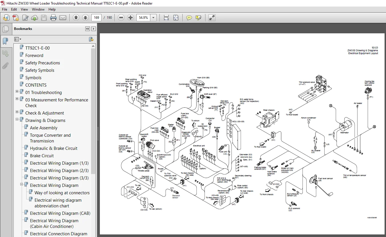
TT92C1-E-00...........................................................................................................................................  1
Foreword..............................................................................................................................................  2
Safety Precautions....................................................................................................................................  3
Safety Symbols........................................................................................................................................  4
Symbols...............................................................................................................................................  5
CONTENTS..............................................................................................................................................  6
01 Troubleshooting....................................................................................................................................  8
	Cautions Regarding Troubleshooting................................................................................................................ 10
	How to Use Quick Troubleshooting Table............................................................................................................ 11
	Safety Precautions................................................................................................................................ 12
	Torque Converter and Transmission Group........................................................................................................... 13
		1. Machine dose not move in any shift lever position.......................................................................................... 13
		2. Machine dose not move at a certain shift lever position. (OR:Machine moves only in a certain shift lever position.)........................ 14
		3. Machine moves at the neutral position. (Example: Machine moves forward at the neutral position.)........................................... 15
		4. Large shock at starting or changing speed / direction...................................................................................... 16
		5. Large time lag at starting or changing speed / direction................................................................................... 17
		6. Low power of traction / pushing (Defective torque converter or transmission)............................................................... 18
		7. Torque converter oil is overheating........................................................................................................ 19
		8. Machine moves reverse when starting to climb up on a slope using inching brake............................................................. 20
		9. Automatic speed change is not possible..................................................................................................... 21
		10. Downshift button does not work............................................................................................................ 22
	Hydraulic Group................................................................................................................................... 23
		1. Boom and/or bucket do not move............................................................................................................. 23
		2. Boom and/or bucket have low power, or move too slowly...................................................................................... 24
		3. Excessive cylinder drift................................................................................................................... 25
		4. Boom and/or bucket are spongy. (Holding bucket against the ground is not possible-front wheels off the ground.)............................ 26
		5. Bucket leveler does not work. Boom lift kickout and lower kickout does not work............................................................ 27
		6. Steering is not possible or hard to steer.................................................................................................. 28
		7. Machine sways, or has a shock during steering.............................................................................................. 29
		8. ELS (Efficient Loading System) does not work. (Excavating and scooping tractive power does not become up during ELS working condition.).... 30
		9. Ride control does not work................................................................................................................. 31
		10. Fan motor rotates abnormally or does not rotate........................................................................................... 32
		11. Abnormal noise in hydraulic system........................................................................................................ 33
		12. Others.................................................................................................................................... 34
	Brake Group....................................................................................................................................... 35
		1. Brake does not work well. (In the worst case, the brake does not work at all.)............................................................. 35
		2. Brake is dragging when released............................................................................................................ 36
		3. Stepping on the brake pedal sounds the buzzer.............................................................................................. 37
		4. Accumulator pressure does not rise, or too slow in rising.................................................................................. 38
		5. Parking brake does not work. (or: Releasing the parking brake is not possible.)............................................................ 39
	Electrical Group.................................................................................................................................. 40
		1. Instrument panel does not indicate properly................................................................................................ 40
		2. Fuse for controller is blown............................................................................................................... 41
		Error code (for chassis)...................................................................................................................... 42
		Error code (for engine)....................................................................................................................... 45
	Operator Station Group............................................................................................................................ 52
		Air conditioner............................................................................................................................... 52
03 Measurement for Performance Check.................................................................................................................. 60
	Cautions on Safety................................................................................................................................ 61
	Standard Measurement Values for Performance Check................................................................................................. 62
	Preparation for Performance Check................................................................................................................. 65
	Engine............................................................................................................................................ 67
		Measuring engine speed........................................................................................................................ 67
			Measurement instrument.................................................................................................................... 67
			Standard measurement value (Normal mode).................................................................................................. 67
	Clutch Oil Pressure............................................................................................................................... 71
		Measuring clutch oil pressure................................................................................................................. 71
	Hydraulic Cylinder................................................................................................................................ 72
		Cylinder natural drift........................................................................................................................ 72
			Measurement instrument.................................................................................................................... 72
			Standard measurement value (mm/min) (in/min).............................................................................................. 72
			Measurement procedure..................................................................................................................... 72
	Boom Rising Time.................................................................................................................................. 73
		Measurement instrument........................................................................................................................ 73
		Warm-up the engine before measuring boom rising time.......................................................................................... 73
		Standard measurement value (sec).............................................................................................................. 73
		Measurement procedure......................................................................................................................... 73
	Full Steering Cycle Time.......................................................................................................................... 75
		Measurement instrument........................................................................................................................ 75
		Warm-up the engine before measuring full steering time........................................................................................ 75
		Standard measurement value (sec).............................................................................................................. 75
		Measurement procedure......................................................................................................................... 75
	Loading/Steering Circuit Relief Valve............................................................................................................. 77
		Loading circuit relief valve setting pressures................................................................................................ 77
			Measurement instruments................................................................................................................... 77
			Gauge port................................................................................................................................ 77
			Standard measurement value MPa (kgf/cm2) (psi)............................................................................................ 78
			Measuring loading circuit main relief pressure............................................................................................ 78
			Measuring loading circuit overload relief pressure........................................................................................ 80
			Measuring pilot circuit relief pressure................................................................................................... 81
		Steering circuit relief valve setting pressures............................................................................................... 82
			Measurement instruments................................................................................................................... 82
			Gauge port................................................................................................................................ 82
			Standard measurement value MPa (kgf/cm2) (psi)............................................................................................ 83
			Measuring steering circuit main relief pressure........................................................................................... 83
			Measuring steering circuit overload relief pressure....................................................................................... 85
			Measuring pilot circuit relief pressure (reducing pressure)............................................................................... 86
	Service Brake..................................................................................................................................... 88
		Service brake performance check............................................................................................................... 88
			Condition................................................................................................................................. 88
			Standard measurement value................................................................................................................ 88
	Parking Brake..................................................................................................................................... 89
		Parking brake performance check............................................................................................................... 89
			Condition................................................................................................................................. 89
			Standard measurement value................................................................................................................ 89
	Brake Circuit Oil Pressure........................................................................................................................ 90
		Unloader valve setting pressure............................................................................................................... 90
			Measurement instrument.................................................................................................................... 91
			Gauge port................................................................................................................................ 91
			Standard measurement value................................................................................................................ 91
			Measurement procedure..................................................................................................................... 91
		Brake valve oil pressure...................................................................................................................... 93
			Measurement instrument.................................................................................................................... 93
			Gauge port................................................................................................................................ 93
			Measurement procedure..................................................................................................................... 93
			Brake valve performance................................................................................................................... 94
	Accumulator Circuit Charging Time................................................................................................................. 95
		Measurement instrument........................................................................................................................ 95
		Gauge installation position................................................................................................................... 95
		Standard measurement valve (sec).............................................................................................................. 96
		Measurement procedure......................................................................................................................... 96
	Number of Brake Pedal Applications................................................................................................................ 97
		Standard measurement value.................................................................................................................... 97
		Measurement procedure......................................................................................................................... 97
		Possible causes of extremely low measurement value and solution............................................................................... 97
	Declutch Engagement............................................................................................................................... 98
		Measurement instrument........................................................................................................................ 98
		Warm-up the engine before measuring declutch engagement....................................................................................... 98
		Standard measurement value.................................................................................................................... 98
		Cause of extremely high measurement value and solution........................................................................................ 98
		Measurement procedure......................................................................................................................... 98
	MEMO.............................................................................................................................................. 99
Check & Adjustment....................................................................................................................................100
	13 Check & Adjustment Chassis Group...............................................................................................................102
		Linkage Pin...................................................................................................................................103
			Liner.....................................................................................................................................103
				Adjustment............................................................................................................................104
				Bucket hinge pin section..............................................................................................................105
				How to assemble.......................................................................................................................105
		Center Pin....................................................................................................................................106
			Adjusting shim............................................................................................................................106
			Installing bearing cover..................................................................................................................106
			Installing bearing outer ring.............................................................................................................107
	23 Check & Adjustment Power Group.................................................................................................................108
		Engine........................................................................................................................................109
			Measuring engine speed....................................................................................................................109
				Measurement instrument................................................................................................................109
				Standard measurement value............................................................................................................109
			Measuring engine oil pressure.............................................................................................................109
				Measurement instrument................................................................................................................109
				Install position......................................................................................................................109
				Standard measurement value............................................................................................................109
		Propeller Shaft...............................................................................................................................110
			Propeller shaft phase.....................................................................................................................110
			Second propeller shaft alignment..........................................................................................................110
			Tightening torque.........................................................................................................................111
		Axle..........................................................................................................................................112
			Axle nut tightening procedure.............................................................................................................112
			Differential gear adjustment procedure....................................................................................................113
				Preload adjustment....................................................................................................................113
				Bearing installation..................................................................................................................114
				Oil seal installation.................................................................................................................114
				Adjusting tooth contact...............................................................................................................115
		MEMO..........................................................................................................................................117
	33 Check & Adjustment Torque Converter and Transmission Group.....................................................................................118
		Clutch Oil Pressure...........................................................................................................................119
			Measuring clutch oil pressure.............................................................................................................119
	43 Check & Adjustment Hydraulic Group.............................................................................................................120
		Loading/Steering Circuit Relief Valve/Ride Control Circuit Reducing Valve (OPT)...............................................................121
			Loading circuit relief valve setting pressures............................................................................................121
				Measurement instruments...............................................................................................................121
				Gauge port............................................................................................................................121
				Standard measurement value MPa (kgf/cm2) (psi)........................................................................................122
				Measuring loading circuit main relief pressure........................................................................................122
				Measuring loading circuit overload relief pressure....................................................................................124
				Measuring pilot circuit relief pressure...............................................................................................125
			Ride control circuit reducing valve setting pressures (OPT)...............................................................................126
				Measurement instruments...............................................................................................................126
				Gauge port............................................................................................................................126
				Standard measurement value MPa (kgf/cm2) (psi)........................................................................................127
				Measuring ride control circuit reducing pressure......................................................................................127
			Steering circuit relief valve setting pressures...........................................................................................129
				Measurement instruments...............................................................................................................129
				Gauge port............................................................................................................................129
				Standard measurement value MPa (kgf/cm2) (psi)........................................................................................130
				Measuring steering circuit main relief pressure.......................................................................................130
				Measuring steering circuit overload relief pressure...................................................................................132
				Measuring pilot circuit relief pressure (reducing pressure)...........................................................................133
		Hydraulic Cylinder............................................................................................................................134
			Cylinder natural drift....................................................................................................................134
				Measurement instrument................................................................................................................134
				Standard measurement value (mm/min) (in/min)..........................................................................................134
				Measurement procedure.................................................................................................................134
		Stop Valve....................................................................................................................................136
			Stop valve adjustment procedure...........................................................................................................136
		MEMO..........................................................................................................................................137
	53 Check & Adjustment Brake Group.................................................................................................................138
		Brake Circuit Oil Pressure....................................................................................................................139
			Unloader valve setting pressure...........................................................................................................139
				Measurement instrument................................................................................................................140
				Gauge port............................................................................................................................140
				Standard measurement value............................................................................................................140
				Measurement procedure.................................................................................................................140
			Brake valve oil pressure..................................................................................................................141
				Measurement instrument................................................................................................................141
				Gauge port............................................................................................................................141
				Measurement procedure.................................................................................................................141
				Brake valve performance...............................................................................................................142
		Service Brake.................................................................................................................................143
			Service brake performance check...........................................................................................................143
				Condition.............................................................................................................................143
				Standard measurement value............................................................................................................143
			Service brake friction plate wear measurement.............................................................................................144
				Measurement procedure.................................................................................................................145
			Cautions on installing brake discs........................................................................................................145
		Parking Brake.................................................................................................................................146
			Parking brake performance check...........................................................................................................146
				Condition.............................................................................................................................146
				Standard measurement value............................................................................................................146
Drawing & Diagrams....................................................................................................................................147
	Axle Assembly.....................................................................................................................................148
	Torque Converter and Transmission.................................................................................................................149
	Hydraulic & Brake Circuit.........................................................................................................................150
	Brake Circuit.....................................................................................................................................151
	Electrical Wiring Diagram (1/3)...................................................................................................................152
	Electrical Wiring Diagram (2/3)...................................................................................................................153
	Electrical Wiring Diagram (3/3)...................................................................................................................154
	Electrical Wiring Diagram.........................................................................................................................155
		Way of looking at connectors..................................................................................................................155
		Electrical wiring diagram abbreviation chart..................................................................................................157
	Electrical Wiring Diagram (CAB)...................................................................................................................158
	Electrical Wiring Diagram (Cabin Air Conditioner).................................................................................................159
	Electrical Connection Diagram (1/2)...............................................................................................................160
	Electrical Connection Diagram (2/2)...............................................................................................................161
	Electrical Circuit Diagram (Cabin Air Conditioner)................................................................................................162
	Electrical Equipment Layout.......................................................................................................................163
	Equipment Operation Table (Cabin Air Conditioner).................................................................................................172
	Outline of MODM (Machine Operation Diagnostic Module) Operation...................................................................................173
	MODM: Input/Output Monitor - Input/Output Signal Correspondence Table.............................................................................182
Maintenance Log.......................................................................................................................................183
Notes.................................................................................................................................................187
Please Note:
⦁ This is the SAME exact manual used by your dealers to fix your vehicle.
⦁ The same can be yours in the next 2-3 mins as you will be directed to the download page immediately after paying for the manual.
⦁ Any queries / doubts regarding your purchase, please feel free to contact [email protected]