Hitachi ZW550 6 Wheel Loader Operational Principle Technical Manual TONHK40 EN 00 – PDF DOWNLOAD
Original price was: $88.95.$21.95Current price is: $21.95.
Hitachi ZW550 6 Wheel Loader Operational Principle Technical Manual TONHK40 EN 00
Part No : TONHK40-EN-00
Description
Hitachi ZW550 6 Wheel Loader Operational Principle Technical Manual TONHK40 EN 00
File details:
Hitachi ZW550 6 Wheel Loader Operational Principle Technical Manual TONHK40 EN 00
Language : English
Pages : 497
Size : 40.9 MB
Downloadable : Yes
Format : PDF
Part No : TONHK40-EN-00
HITACHI ZW550 6 WHEEL LOADER OPERATIONAL PRINCIPLE TECHNICAL MANUAL TONHK40 EN 00 – PDF DOWNLOAD:
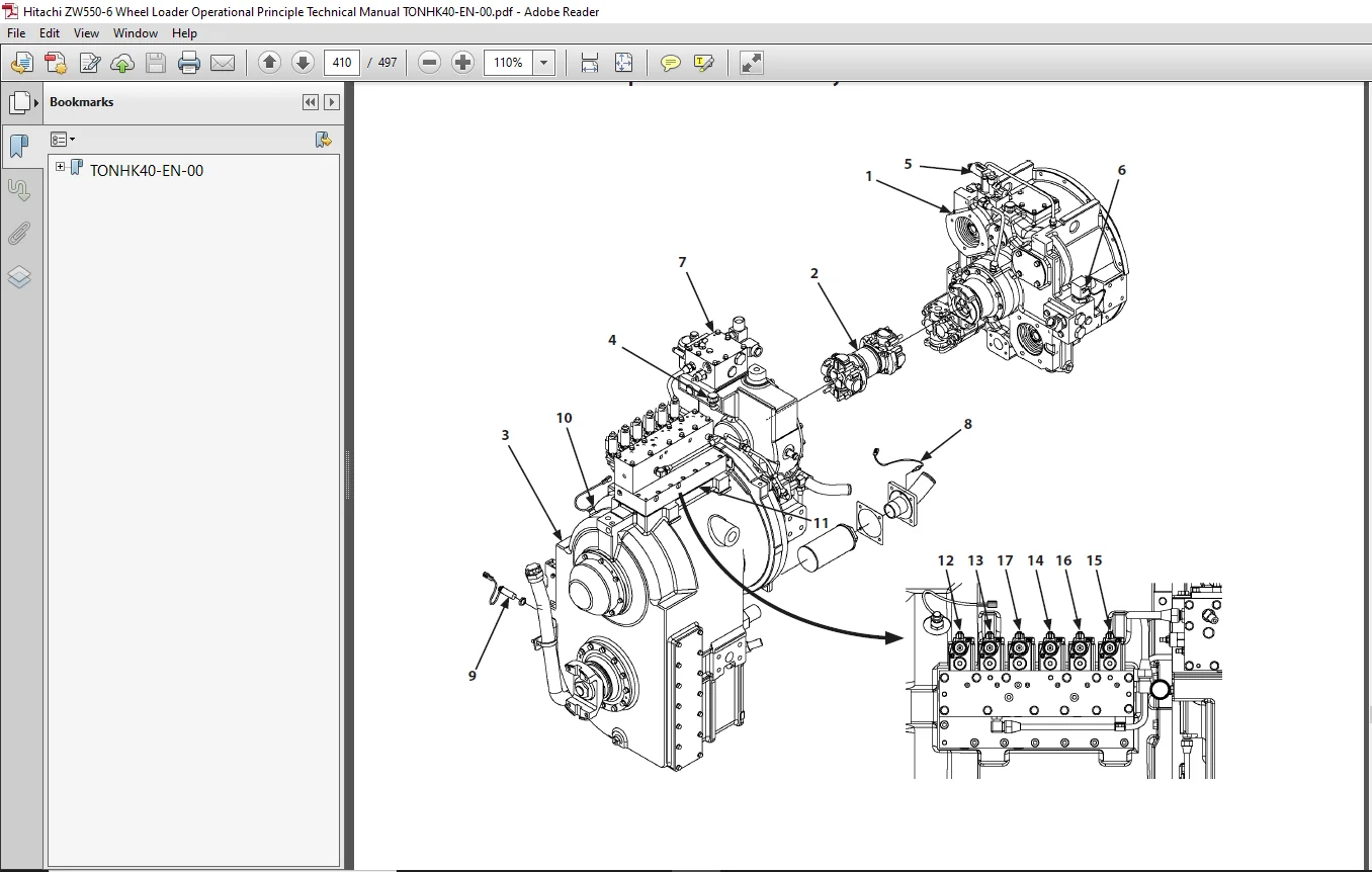
Image Preview:
Table of Contents:
Hitachi ZW550 6 Wheel Loader Operational Principle Technical Manual TONHK40 EN 00
TONHK40-EN-00...................................................................................  1
	CONTENTS....................................................................................  3
		SECTION 1 GENERAL.......................................................................  3
		SECTION 2 SYSTEM........................................................................  5
		SECTION 3 COMPONENT OPERATION...........................................................  7
	INTRODUCTION................................................................................  9
		To The Reader...........................................................................  9
		Additional References...................................................................  9
		Manual Composition......................................................................  9
		Page Number.............................................................................  9
		Trademark...............................................................................  9
		Safety Alert Symbol and Headline Notations.............................................. 10
		Units Used.............................................................................. 10
	SYMBOL AND ABBREVIATION..................................................................... 11
	SECTION AND GROUP CONTENTS.................................................................. 13
	SECTION 1 GENERAL........................................................................... 15
		Group 1 Specifications.................................................................. 17
			Specifications...................................................................... 17
			Weight of Main Components........................................................... 18
		Group 2 Component Layout................................................................ 21
			Main Component (Overview)........................................................... 21
			Main Component...................................................................... 22
			Main Component...................................................................... 23
			Electric Component Layout (Front Chassis)........................................... 24
			Electric Component Layout (Rear Grill).............................................. 25
			Electrical System (Cab)............................................................. 26
			Electrical System (Around Battery Box).............................................. 32
			Electrical System (Around Hydraulic Tank)........................................... 33
			Electrical System (Around Fuel Tank)................................................ 34
			Electrical System (Rear Chassis Center Frame)....................................... 35
			Engine.............................................................................. 36
			Aftertreatment Device............................................................... 37
			Hydraulic Pump...................................................................... 38
			Transmission and Torque Converter Assembly.......................................... 40
			Multiple Control Valve.............................................................. 41
			Unloader Valve (Brake Charge Valve) and Combination Valve (Brake Manifold Valve).... 42
			Steering Valve...................................................................... 43
			Flow Regulator Valve................................................................ 43
			Ride Control Valve (Option)......................................................... 44
			Emergency Steering Pump (Option).................................................... 44
		Group 3 Component Specifications........................................................ 45
			Engine.............................................................................. 45
			Engine Accessories.................................................................. 48
			Hydraulic Component................................................................. 50
			Electrical Component................................................................ 55
	SECTION 2 SYSTEM............................................................................ 59
		Group 1 Controller...................................................................... 61
			Outline............................................................................. 61
			CAN Circuit......................................................................... 62
		Group 2 Control System.................................................................. 65
			Outline............................................................................. 65
			Engine Control...................................................................... 68
			Pump Control........................................................................ 85
			Transmission Control................................................................ 92
			Fan Control, Valve Control..........................................................115
			Other Controls......................................................................127
			Combined Electric and Hydraulic Control Circuit.....................................147
		Group 3 Engine System...................................................................153
			Outline.............................................................................153
			Engine Sensors......................................................................156
			Fuel Injection Control..............................................................157
			EGR Control.........................................................................162
			Preheating Control..................................................................164
			Variable Turbocharger Control.......................................................165
			Urea SCR System.....................................................................166
			Engine Output Restriction (Inducement)..............................................170
			Aftertreatment Device...............................................................174
			Aftertreatment Device Regeneration Control..........................................176
		Group 4 Hydraulic System................................................................179
			Outline.............................................................................179
			Pilot Circuit.......................................................................180
			Brake Priority Circuit..............................................................182
			Service Brake Circuit...............................................................188
			Parking Brake Circuit...............................................................190
			Auto Brake Circuit..................................................................192
			Lift Arm / Bucket Operation Control Circuit.........................................194
			Fan Circuit.........................................................................198
			Main Circuit........................................................................200
			Steering Priority Circuit...........................................................202
			Steering Operation Control Circuit..................................................206
			Neutral Circuit.....................................................................212
			Flow Rate Control Circuit...........................................................212
			Relief Circuit......................................................................212
			Other Circuits......................................................................212
			Pump Control Circuit................................................................214
			Parallel Circuit Flow Rate Control..................................................216
			Single Operation Circuit............................................................218
			Combined Operation Circuit..........................................................220
			Ride Control Circuit (Option).......................................................224
			Emergency Steering Circuit (Option).................................................226
		Group 5 Electrical System...............................................................229
			Outline.............................................................................229
			Main Circuit........................................................................230
			Electric Power Circuit (Key Switch: OFF)............................................232
			CAN Circuit.........................................................................234
			Accessory Circuit (Key Switch: ACC).................................................236
			Starting Circuit (Key Switch: START)................................................238
			Neutral Engine Start Circuit........................................................240
			Charging Circuit (Key Switch: ON)...................................................242
			Surge Voltage Prevention Circuit....................................................246
			Pilot Shut-Off Circuit (Key Switch: ON).............................................248
			Auto Idling Stop Circuit............................................................250
			Engine Stop Circuit.................................................................252
			Monitor Circuit.....................................................................255
			Air Conditioner Circuit.............................................................256
			Steering Column Monitor Circuit.....................................................259
			Head Light Circuit..................................................................260
			Hazard Light Circuit (Key Switch: OFF)..............................................266
			Turn Signal Light Circuit...........................................................268
			Horn Circuit (Key Switch: OFF)......................................................270
			Reverse Light/Buzzer Circuit........................................................272
			Brake Light Circuit.................................................................274
			Parking Brake Circuit...............................................................276
			Accessory Circuit...................................................................281
			Work Light Circuit..................................................................282
			Wiper Circuit.......................................................................284
			Cab Light Circuit...................................................................290
	SECTION 3 COMPONENT OPERATION...............................................................295
		Group 1 Pump Device.....................................................................297
			Hydraulic Pump Outline..............................................................297
			Main Hydraulic Pump.................................................................298
			Regulator...........................................................................301
			Pilot Pump..........................................................................304
			Pump Delivery Pressure Sensor.......................................................306
		Group 2 Control Valve...................................................................307
			Outline.............................................................................307
			Hydraulic Circuit...................................................................312
			Main Relief Valve...................................................................314
			Main Relief Valve Operation.........................................................315
			Overload Relief Valve (with Make-Up Function).......................................316
			Bleed-Off Compensation Spool........................................................320
			Bucket Spool........................................................................322
			Lift Arm Spool......................................................................326
			Lift Arm Flow Rate Control Valve....................................................332
			Ride Control (Option)...............................................................334
			Pump Control Valve (Negative Control Relief Valve)..................................336
		Group 3 Cooling Fan System..............................................................339
			Cooling Fan System Layout...........................................................339
			Fan Pump (Pilot Pump)...............................................................340
			Fan Motor...........................................................................341
			Fan Control Valve...................................................................342
		Group 4 Steering Pilot Valve............................................................351
			Outline.............................................................................351
			Location............................................................................351
			Overview............................................................................352
			Steering Pilot Valve Specifications.................................................352
			Structure...........................................................................353
			Operation...........................................................................354
			Joystick Steering Control Valve (Option)............................................358
		Group 5 Steering Valve..................................................................363
			Outline.............................................................................363
			Operation...........................................................................366
			Steering Valve Meter-In Compensator.................................................370
			Steering Main Relief Valve..........................................................372
			Steering Overload Relief Valve......................................................374
			Steering Spool Variable Orifice.....................................................379
			Steering Pilot Circuit and Its Operation............................................380
			Flow Amplifier Notch and Pilot Orifice..............................................382
		Group 6 Pilot Valve.....................................................................383
			Outline (Fingertip Control Type Pilot Valve for Front Attachment)...................383
			Operation...........................................................................384
			Electromagnetic Detent..............................................................388
			Outline (Joystick Type Pilot Valve for Front Attachment)............................389
			Operation...........................................................................391
			Electromagnetic Detent..............................................................398
		Group 7 Charging Circuit................................................................399
			Outline.............................................................................399
			Brake Charge Valve (Unloader Valve).................................................400
			Combination Valve (Manifold Block)..................................................402
			Combination Valve (Solenoid Valve Block)............................................406
			Service Brake Accumulator...........................................................408
		Group 8 Drive Unit......................................................................409
			Outline.............................................................................409
			Transmission and Torque Converter Assembly..........................................410
			Drive Unit Hydraulic Circuit Diagram................................................411
			Torque Converter (Lock-Up)..........................................................412
			Transmission........................................................................414
			Operation of Transmission...........................................................417
			Clutch Pack.........................................................................419
			Power Flow Path in the Transmission.................................................420
			Transmission Control Valve..........................................................426
			Lock-Up Clutch Valve Assy...........................................................429
		Group 9 Axle............................................................................431
			Outline.............................................................................431
			Front Axle Assembly.................................................................432
			Rear Axle Assembly..................................................................434
			Differential Gear (Conventional Type)...............................................436
			Limited Slip Differential (LSD) (Option)............................................442
			Service Brake.......................................................................444
			Parking Brake.......................................................................446
			Parking Brake Manual Release........................................................447
		Group 10 Brake Valve....................................................................449
			Outline.............................................................................449
			Service Brake Operation.............................................................452
			Bleed Air from Service Brake Circuit................................................453
			Pressure Switch (for Stop Lamp).....................................................454
			Pressure Sensor (for Declutch)......................................................455
			Auto Brake Operation................................................................456
			Bleed Air from Auto Brake Circuit...................................................457
		Group 11 DEF Supply System..............................................................459
			System Overview.....................................................................459
			DEF.................................................................................460
			DEF Tank............................................................................460
			Hose Urea...........................................................................461
			DEF/AdBlue Sensor Unit..............................................................462
			DEF/AdBlue Supply Module............................................................464
			Coolant Line........................................................................466
			Coolant Control Valve Air Bleeding Procedure........................................468
		Group 12 Others.........................................................................471
			Propeller Shaft.....................................................................471
			Emergency Steering Pump.............................................................475
			Flow Regulator Valve................................................................476
			Ride Control Valve..................................................................478
			Ride Control Accumulator............................................................482
			Steering Accumulator................................................................483
			Priority Hammer Valve...............................................................484
			Axle Oil Cooler.....................................................................488
	SERVICE MANUAL REVISION REQUEST FORM........................................................497
Description:
Hitachi ZW550 6 Wheel Loader Operational Principle Technical Manual TONHK40 EN 00
INTRODUCTION:
TO THE READER:
• This manual is written for an experienced technician to provide technical information needed to maintain and repair this machine.
• Be sure to thoroughly read this manual for correct product information and service procedures.
• If you have any questions or comments, at if you found any errors regarding the contents of this manual, please contact using “Service Manual Revision Request Form” at the end of this manual.
ADDITIONAL REFERENCES:
• Please refer to the materials listed below in addition to this manual.
• The Operator’s Manual
• The Parts Catalog
• The Engine Manual
• Parts Catalog of the Engine
• Hitachi Training Material
MANUAL COMPOSITION:
• This manual consists of three portions: the Technical Manual (Operational Principle), the Technical Manual (Troubleshooting) and the Workshop Manual.
• Information included in the Technical Manual (Operational Principle): technical information needed for redelivery and delivery, operation and activation of all devices and systems.
• Information included in the Technical Manual (Troubleshooting): technical information needed for operational performance tests, and troubleshooting procedures.
• Information included in the Workshop Manual: technical information needed for maintenance and repair of the machine, tools and devices needed for maintenance and repair, maintenance standards, and removal/installation and assemble/ disassemble procedures.
Please Note:
- This is the SAME exact manual used by your dealers to fix your vehicle.
- The same can be yours in the next 2-3 mins as you will be directed to the download page immediately after paying for the manual.
- Any queries / doubts regarding your purchase, please feel free to contact [email protected]