Hitachi ZW550 6 Wheel Loader Operational Principle+Troubleshooting+Workshop Manual – PDF DOWNLOAD
Original price was: $56.95.$32.95Current price is: $32.95.
Hitachi ZW550 6 Wheel Loader Operational Principle+Troubleshooting+Workshop Manual
This Listing includes all of the manuals mentioned below:
- Hitachi ZW550-6 Hydraulic Circuit Diagram TTNK40-EN-00
- Hitachi ZW550-6 Hydraulic Circuit Diagram
- Hitachi ZW550-6 Wheel Loader Floor Cable Layout Electrical Circuit Diagram
- Hitachi ZW550-6 Wheel Loader Operational Principle Technical Manual TONHK40-EN-00
- Hitachi ZW550-6 Wheel Loader Operational Principle Technical Manual TONHK70-EN-00
- Hitachi ZW550-6 Wheel Loader Troubleshooting Technical Manual TTNHK40-EN-00
- Hitachi ZW550-6 Wheel Loader Troubleshooting Technical Manual TTNHK70-EN-00
- Hitachi ZW550-6 Wheel Loader Troubleshooting Technical Manual
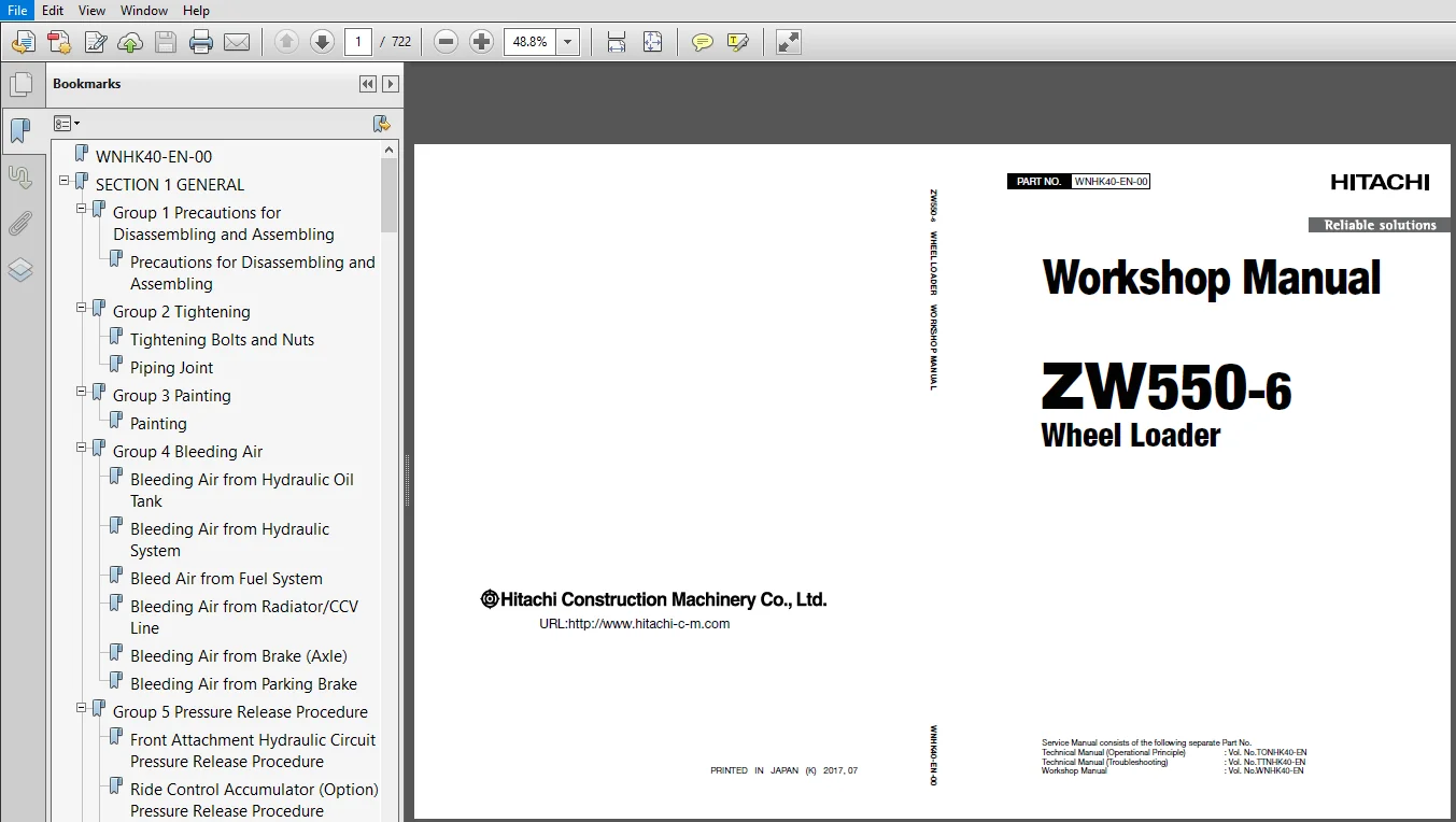
- Hitachi ZW550-6 Wheel Loader Workshop Manual WNHK40-EN-00
- Hitachi ZW550-6 Wheel Loader Workshop Manual WNHK70
- Hitachi ZW550-6 Wheel Loader Workshop Manual WNHK70-EN-00
- Hitachi ZW550-6 Wheel Loader Workshop Manual
Description
Hitachi ZW550 6 Wheel Loader Operational Principle+Troubleshooting+Workshop Manual
FILE DETAILS:
Hitachi ZW550 6 Wheel Loader Operational Principle+Troubleshooting+Workshop Manual
This Listing includes all of the manuals mentioned below:
- Hitachi ZW550-6 Hydraulic Circuit Diagram TTNK40-EN-00
- Hitachi ZW550-6 Hydraulic Circuit Diagram
- Hitachi ZW550-6 Wheel Loader Floor Cable Layout Electrical Circuit Diagram
- Hitachi ZW550-6 Wheel Loader Operational Principle Technical Manual TONHK40-EN-00
- Hitachi ZW550-6 Wheel Loader Operational Principle Technical Manual TONHK70-EN-00
- Hitachi ZW550-6 Wheel Loader Troubleshooting Technical Manual TTNHK40-EN-00
- Hitachi ZW550-6 Wheel Loader Troubleshooting Technical Manual TTNHK70-EN-00
- Hitachi ZW550-6 Wheel Loader Troubleshooting Technical Manual
- Hitachi ZW550-6 Wheel Loader Workshop Manual WNHK40-EN-00
- Hitachi ZW550-6 Wheel Loader Workshop Manual WNHK70
- Hitachi ZW550-6 Wheel Loader Workshop Manual WNHK70-EN-00
- Hitachi ZW550-6 Wheel Loader Workshop Manual
DESCRIPTION:
Hitachi ZW550 6 Wheel Loader Operational Principle+Troubleshooting+Workshop Manual
INTRODUCTION:
TO THE READER:
• This manual is written for an experienced technician to provide technical information needed to maintain and repair this machine.
• Be sure to thoroughly read this manual for correct product information and service procedures.
• If you have any questions or comments, at if you found any errors regarding the contents of this manual, please contact using “Service Manual Revision Request Form” at the end of this manual.
ADDITIONAL REFERENCES:
• Please refer to the materials listed below in addition to this manual.
• The Operator’s Manual
• The Parts Catalog
• The Engine Manual
• Parts Catalog of the Engine
• Hitachi Training Material
MANUAL COMPOSITION:
• This manual consists of three portions: the Technical Manual (Operational Principle), the Technical Manual (Troubleshooting) and the Workshop Manual.
• Information included in the Technical Manual (Operational Principle): technical information needed for redelivery and delivery, operation and activation of all devices and systems.
• Information included in the Technical Manual (Troubleshooting): technical information needed for operational performance tests, and troubleshooting procedures.
• Information included in the Workshop Manual: technical information needed for maintenance and repair of the machine, tools and devices needed for maintenance and repair, maintenance
standards, and removal/installation and assemble/ disassemble procedures.
TABLE OF CONTENTS:
Hitachi ZW550 6 Wheel Loader Operational Principle+Troubleshooting+Workshop Manual
- Hitachi ZW550-6 Wheel Loader Workshop Manual
Group 1 Tire
Removal and Installation of Front TireW4-1-1-1
Removal and Installation of Rear TireW4-1-2-1
Group 2 Drive Unit
Removal and Installation of Torque ConverterW4-2-1-1
Disassembly and Assembly of Torque
ConverterW4-2-2-1
Disassembly and Assembly of Torque
Converter Sub AssemblyW4-2-2-10
Removal and Installation of TransmissionW4-2-3-1
Disassembly and Assembly of Transmission
AssyW4-2-4-1
Disassembly and Assembly of Clutch
AssemblyW4-2-5-1
Disassembly and Assembly of Low and Third
Speed Clutch AssemblyW4-2-5-16
Disassembly and Assembly of Second Speed
Clutch AssemblyW4-2-5-19
Disassembly and Assembly of Reverse Clutch
AssemblyW4-2-5-22
Disassembly and Assembly of First Clutch
AssemblyW4-2-5-25
Disassembly and Assembly of High Clutch
Spider AssemblyW4-2-5-31
Disassembly and Assembly of Gear Box
AssemblyW4-2-6-1
Removal and Installation of Transmission
Control Valve W4-2-8-1
Disassembly and Assembly of Transmission
Control Valve W4-2-9-1
Special Tools (For Transmission Assembly and
Disassembly)W4-2-10-1
Drawings for Special ToolsW4-2-10-2
Group 3 Axle
Removal and Installation of Front AxleW4-3-1-1
Removal and Installation of Rear AxleW4-3-2-1
Disassembly of AxleW4-3-3-1
Assembly of AxleW4-3-3-9
Disassembly and Assembly of Spider
AssemblyW4-3-3-20
Disassembly and Assembly of Internal
Gear Hub AssemblyW4-3-3-22
Removal and Installation of Floating SealW4-3-3-26
Removal and Installation of DifferentialW4-3-4-1
Disassembly and Assembly of DifferentialW4-3-5-1
Disassembly and Assembly of Parking Brake
Piston AssemblyW4-3-5-23
Special Tools For Axle AssemblyW4-3-6-1
Drawings for Special ToolsW4-3-6-2
Group 4 Propeller Shaft
Removal and Installation of Propeller ShaftW4-4-1-1
Group 5 Brake Valve
Removal and Installation of Brake ValveW4-5-1-1
Disassembly and Assembly of Brake Valve
AssemblyW4-5-2-1
Disassembly and Assembly of Brake ValveW4-5-3-1
Maintenance StandardW4-5-3-5
Group 6 Steering Pilot Valve
Removal and Installation of Steering Pilot
ValveW4-6-1-1
Disassembly of Steering Pilot Valve W4-6-2-1
Assembly of Steering Pilot Valve W4-6-2-4
Group 7 Steering Valve
Removal and Installation of Steering Valve W4-7-1-1
Disassembly of Steering ValveW4-7-2-1
Assembly of Steering ValveW4-7-2-4
Group 8 Steering Cylinder
Removal and Installation of Steering CylinderW4-8-1-1
Disassembly of Steering CylinderW4-8-2-1
Assembly of Steering CylinderW4-8-2-4
Removal and Installation of Steering
AccumulatorW4-8-3-1
Tools for Steering Cylinder Disassembly and
AssemblyW4-8-4-1
Group 9 Emergency Steering Device
Removal and Installation of Emergency
Steering PumpW4-9-1-1
Group 10 Reducing Valve
Removal and Installation of Reducing ValveW4-10-1-1
Disassembly of Reducing ValveW4-10-2-1
Assembly of Reducing ValveW4-10-2-3
Group 11 Stop Valve
Removal and Installation of Stop ValveW4-11-1-1
Disassembly of Stop ValveW4-11-2-1
Assembly of Stop ValveW4-11-2-2
SECTION 4
TRAVEL SYSTEM
CONTENTS
WNHK40-EN-00(20180806)
NHK40W-4-2
Group 12 Main Pressure Block
Removal and Installation of Main Pressure
BlockW4-12-1-1
Structure of Main Pressure BlockW4-12-1-3
Group 13 Priority Hammer Valve and Shuttle
Valve
Removal and Installation of Priority Hammer
Valve and Shuttle ValveW4-13-1-1
Structure of Priority Hammer Valve and
Shuttle ValveW4-13-1-5
Group 14 Check Valve
Removal and Installation of Check
ValveW4-14-1-1
Structure of Check ValveW4-14-1-3
- Hitachi ZW550-6 Wheel Loader Operational Principle Technical Manual
SECTION 1 GENERAL
Group 1 Specifications
Group 2 Component Layout
Group 3 Component Specifications
SECTION 2 SYSTEM
Group 1 Controller
Group 2 Control System
Group 3 Engine System
Group 4 Hydraulic System
Group 5 Electrical System
SECTION 3 COMPONENT OPERATION
Group 1 Pump Device
Group 2 Control Valve
Group 3 Cooling Fan System
Group 4 Steering Pilot Valve
Group 5 Steering Valve
Group 6 Pilot Valve
Group 7 Charging Circuit
Group 8 Drive Unit
Group 9 Axle
Group 10 Brake Valve
Group 11 DEF Supply System
Group 12 Others
- Hitachi ZW550-6 Wheel Loader Troubleshooting Technical Manual
SECTION 4
OPERATIONAL PERFORMANCE TEST CONTENTS
Group 1 Introduction
Operational Performance Tests T4-1-1
Preparation for Performance Tests T4-1-2
Group 2 Standard
Operational Performance Standard Table T4-2-1
Sensor Activating RangeT4-2-10
Group 3 Engine Test
Engine Speed T4-3-1
Group 4 Machine Performance Test
Travel Speed T4-4-1
Service Brake Function Check T4-4-4
Service Brake Wear Amount T4-4-6
Parking Brake Function Check T4-4-7
Bucket Stopper Clearance, Lever (Bell Crank)
Stopper Clearance T4-4-8
Hydraulic Cylinder Cycle TimeT4-4-10
Cylinder Drift CheckT4-4-12
Bucket LevelnessT4-4-13
Control Lever Operating ForceT4-4-14
Control Lever StrokeT4-4-16
Group 5 Component Test
Primary Pilot Pressure
(Unloader Valve Setting Pressure) T4-5-1
Secondary Pilot Pressure T4-5-3
Solenoid Valve Set Pressure T4-5-4
Main Pump Delivery Pressure T4-5-7
Loading Circuit Main Relief Set Pressure T4-5-8
Steering Circuit Main Relief Set PressureT4-5-10
Loading/Steering Overload Relief Valve
Set PressureT4-5-12
Joystick Steering Secondary Pilot PressureT4-5-15
Service Brake Pressure (Front and Rear) T4-5-16
Parking Brake PressureT4-5-18
Brake Accumulator Pressure T4-5-20
Brake Warning Pressure (Pressure-Decreasing)T4-5-22
Brake Warning Pressure (Pressure-Increasing)T4-5-24
Transmission Clutch PressureT4-5-26
Torque Converter PressureT4-5-28
Group 6 Adjustment
Rewrite of Aftertreatment Device Serial No T4-6-1
SECTION 5
TROUBLESHOOTING
Group 1 Diagnosing Procedure
Introduction T5-1-1
Diagnosis Procedure T5-1-2
Electric System Inspection T5-1-5
Precautions for Inspection and Maintenance T5-1-6
Instructions for Disconnecting Connectors T5-1-8
Fuse InspectionT5-1-10
Fusible Link InspectionT5-1-12
Battery Voltage CheckT5-1-13
Alternator CheckT5-1-14
Continuity CheckT5-1-15
Voltage and Current MeasurementT5-1-16
Check by False SignalT5-1-23
Test HarnessT5-1-24
Surge Voltage and Surge Suppression DiodesT5-1-26
Group 2 Monitor
Outline T5-2-1
Operating Procedures of Service Menu T5-2-2
Troubleshooting T5-2-4
Monitoring T5-2-6
Controller VersionT5-2-16
Issued Warning RecordT5-2-17
Communication Terminal StatusT5-2-22
Machine SettingT5-2-24
Engine SettingT5-2-34
Aftertreatment Device NoT5-2-37
Engine Output Restriction SuspendT5-2-38
Engine TachometerT5-2-40
Transmission Oil Temperature Gauge and
DEF/AdBlue Level GaugeT5-2-41
Coolant Temperature GaugeT5-2-42
Group 3 e-Service
Outline T5-3-1
List of Operation Data T5-3-2
Snapshot Data T5-3-6
Communication System T5-3-7
Group 4 Component Layout
Main Component (Overview) T5-4-1
Main Component T5-4-2
Main Component T5-4-3
Electric Component Layout (Front Chassis) T5-4-4
Electric Component Layout (Rear Grill) T5-4-5
Electrical System (Cab) T5-4-6
Electrical System (Around Battery Box)T5-4-12
Electrical System (Around Hydraulic Tank)T5-4-13
Electrical System (Around Fuel Tank)T5-4-14
Electrical System (Rear Chassis Center Frame)T5-4-15
EngineT5-4-16
Aftertreatment DeviceT5-4-17
Hydraulic PumpT5-4-18
Transmission and Torque Converter AssemblyT5-4-20
Multiple Control ValveT5-4-21
Unloader Valve (Brake Charge Valve) and
Combination Valve (Brake Manifold Valve)T5-4-22
Steering ValveT5-4-23
Flow Regulator ValveT5-4-23
Ride Control Valve (Option)T5-4-24
Fuel Priming Pump (us Option)T5-4-24
Secondary Steering Pump (Option)T5-4-24
Group 5 Troubleshooting A
Troubleshooting A (Base Machine Diagnosis
By Using Fault Codes) Procedure T5-5-1
MPDr Fault Code List T5-5-3
MC Fault Code ListT5-5-12
SC Fault Code ListT5-5-28
Monitor Controller (Monitor) Fault Code ListT5-5-41
Monitor Controller (Information) Fault Code ListT5-5-43
Column Display Controller Fault Code ListT5-5-44
Air Conditioner Controller Fault Code ListT5-5-46
ECM Fault Code ListT5-5-49
DCU Fault Code ListT5-5-76
MC Fault Codes 111000 to 111002T5-5-80
SC Fault Codes 111000 to 111002T5-5-80
MC Fault Code 111003T5-5-80
SC Fault Code 111003T5-5-80
MC Fault Codes 111006, 111007,
111009, 111012T5-5-83
SC Fault Codes 111015, 111017,
111019, 111024T5-5-83
Monitor Controller (Monitor) Fault Codes 113002,
113003, 113005, 113010T5-5-84
CAN1 Harness CheckT5-5-85
MC Fault Codes 111008, 111010, 111013,
111014, 111025T5-5-88
SC Fault Codes 111016, 111018, 111020,
111021, 111026T5-5-88
SECTION 5
TROUBLESHOOTING
CONTENTS
TTNHK70-EN-00
NHK70T-5-2
Monitor Controller (Monitor) Fault Codes
113004, 113006, 113007, 113011T5-5-89
CAN2 Harness CheckT5-5-90
MC Fault Codes 111103, 111105, 111106T5-5-93
CAN3 Harness CheckT5-5-94
CAN4 Harness CheckT5-5-97
SC Fault Codes 111205, 111207 T5-5-100
SC Fault Codes 111200, 111202, 111203 T5-5-101
MC Fault Codes 111204, 111312 T5-5-102
SC Fault Codes 111206, 111217 T5-5-103
SC Fault Code 111208 T5-5-104
MC Fault Code 111313 T5-5-105
MC Fault Codes 111600 to 111602 T5-5-106
MC Fault Codes 111210 to 111212 T5-5-107
MC Fault Codes 111214, 111215 T5-5-108
SC Fault Codes 111309, 111310 T5-5-109
SC Fault Code 111407 T5-5-110
SC Fault Code 111410 T5-5-111
SC Fault Code 111411 T5-5-112
SC Fault Code 111412 T5-5-113
MC Fault Code 111413 T5-5-114
MC Fault Code 111414 to 111421 T5-5-115
MC Fault Code 111408 T5-5-117
SC Fault Code 111422 T5-5-118
SC Fault Code 111423 T5-5-119
MC Fault Codes 111502 to 111504,
111506, 111507 T5-5-120
MC Fault Codes 111700 to 111704 T5-5-121
SC Fault Code 111900 T5-5-123
SC Fault Code 111901 T5-5-124
MC Fault Code 111903 T5-5-125
MC Fault Code 111906, 111907 T5-5-126
MC Fault Codes 120014, 120101 to 120104,
120106 T5-5-127
SC Fault Codes 120000 to 120005 T5-5-128
Column Display Controller Fault Code 115001 T5-5-129
Monitor Controller (Monitor)
Fault Code 120300 T5-5-129
Monitor Controller (Information)
Fault Code 113311 T5-5-130
Column Display Controller
Fault Codes 120500 to 120507 T5-5-132
Air Conditioner Controller
Fault Codes 11 to 22 T5-5-133
Air Conditioner Controller
Fault Codes 43 to 92 T5-5-134
Group 6 Troubleshooting B
Troubleshooting B (Machine Diagnosis by Using
Troubleshooting Symptom) Procedure T5-6-1
Relationship between Machine Trouble
Symptoms and Related Parts T5-6-3
Correlation between Trouble Symptoms and
Part FailuresT5-6-27
Engine System TroubleshootingT5-6-47
All Actuator System TroubleshootingT5-6-54
Front Attachment System TroubleshootingT5-6-59
Steering System TroubleshootingT5-6-69
Travel System TroubleshootingT5-6-73
Brake System TroubleshootingT5-6-83
Other System TroubleshootingT5-6-87
Exchange Inspection T5-6-101
Air Bleeding Procedures for Brake (Axle) T5-6-102
Group 7 Air Conditioner
Outline T5-7-1
Functions of Main Parts T5-7-4
Troubleshooting T5-7-9
Air Conditioner Controller Fault Code ListT5-7-10
Air Conditioner Controller Fault Codes 11 to 22T5-7-11
Air Conditioner Controller Fault Codes 43 to 92T5-7-12
Work after Replacing ComponentsT5-7-34
Refill Compressor OilT5-7-35
Charge Air Conditioner with RefrigerantT5-7-36
Hose and Pipe Tightening TorqueT5-7-44
HITACHI ZW550 6 WHEEL LOADER OPERATIONAL PRINCIPLE+TROUBLESHOOTING+WORKSHOP MANUAL – PDF DOWNLOAD:
IMAGES PREVIEW OF THE MANUAL:
PLEASE NOTE:
- This is the SAME manual used by the dealers to troubleshoot any faults in your vehicle. This can be yours in 2 minutes after the payment is made.
- Contact us at [email protected] should you have any queries before your purchase or that you need any other service / repair / parts operators manual.