Trusted Business
Verified & Licensed
Virus Free Files
100% Safe Downloads
Secure Payment
SSL Protected
Instant Delivery
Available Immediately
Sale!

Hitachi ZW550 6 Wheel Loader Workshop Manual WNHK40 EN 00 – PDF DOWNLOAD
Original price was: $92.95.$24.95Current price is: $24.95.
Hitachi ZW550 6 Wheel Loader Workshop Manual WNHK40 EN 00
Part No : TWNHK40-EN-00
Instant PDF Download
Available immediately
Save to Your Device
Download & keep forever
Antivirus Scanned
100% virus-free
Trusted Worldwide
175,000+ customers
Description
Hitachi ZW550 6 Wheel Loader Workshop Manual WNHK40 EN 00
File details:
Hitachi ZW550 6 Wheel Loader Workshop Manual WNHK40 EN 00
Language : English
Pages : 722
Size : 32.4 MB
Downloadable : Yes
Format : PDF
Part No : TWNHK40-EN-00
HITACHI ZW550 6 WHEEL LOADER WORKSHOP MANUAL WNHK40 EN 00 – PDF DOWNLOAD:
Image Preview:
Table of Contents:
Hitachi ZW550 6 Wheel Loader Workshop Manual WNHK40 EN 00
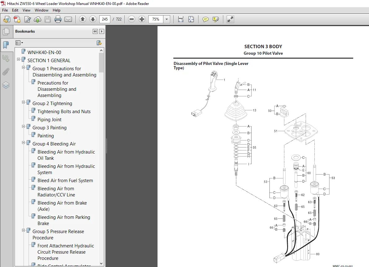
WNHK40-EN-00.....................................................................  1
SECTION 1 GENERAL................................................................  3
	Group 1 Precautions for Disassembling and Assembling.........................  5
		Precautions for Disassembling and Assembling.............................  5
	Group 2 Tightening........................................................... 11
		Tightening Bolts and Nuts................................................ 11
		Piping Joint............................................................. 14
	Group 3 Painting............................................................. 19
		Painting................................................................. 19
	Group 4 Bleeding Air......................................................... 25
		Bleeding Air from Hydraulic Oil Tank..................................... 25
		Bleeding Air from Hydraulic System....................................... 26
		Bleed Air from Fuel System............................................... 27
		Bleeding Air from Radiator/CCV Line...................................... 29
		Bleeding Air from Brake (Axle)........................................... 32
		Bleeding Air from Parking Brake.......................................... 33
	Group 5 Pressure Release Procedure........................................... 35
		Front Attachment Hydraulic Circuit Pressure Release Procedure............ 35
		Ride Control Accumulator (Option) Pressure Release Procedure............. 36
		Parking Brake Accumulator Pressure Release Procedure..................... 37
	Group 6 Preparation.......................................................... 39
		Preparation before Inspection and Maintenance............................ 39
SECTION 2 MAINTENANCE STANDARD................................................... 43
	Group 1 Body................................................................. 45
		Center Hinge............................................................. 45
		Pilot Valve (Two Lever Type )............................................ 47
	Group 2 Front Attachment..................................................... 49
		Pin and Bushing.......................................................... 49
		Standard Dimensions for Lift Arm and Bucket.............................. 51
SECTION 3 BODY................................................................... 53
	Group 1 Cab.................................................................. 55
		Removal and Installation of Cab.......................................... 55
	Group 2 Counterweight........................................................ 71
		Removal and Installation of Counterweight................................ 71
	Group 3 Center Hinge......................................................... 75
		Removal and Installation of Center Hinge................................. 75
		Removal and Installation of the Hydraulic Hoses of Front Chassis Side.... 83
	Group 4 Engine............................................................... 87
		Removal and Installation of Engine....................................... 87
		Removal and Installation of Exterior Parts...............................119
		Removal and Installation of Air Cleaner..................................131
	Group 5 Radiator Assembly....................................................135
		Replacement of Radiator and Cooling System...............................135
	Group 6 Hydraulic Oil Tank...................................................163
		Removal and Installation of Hydraulic Oil Tank...........................163
	Group 7 Fuel Tank............................................................171
		Removal and Installation of Fuel Tank....................................171
	Group 8 Pump Device..........................................................181
		Removal and Installation of Pump Device..................................181
		Disassembly and Assembly of Pump Device..................................187
		Disassembly of Main Pump.................................................191
		Assembly of Main Pump....................................................194
		Disassembly of Regulator.................................................199
		Assembly of Regulator....................................................203
		Removal and Installation of Pilot Pump...................................207
		Disassembly of Pilot Pump................................................209
		Assembly of Pilot Pump...................................................214
	Group 9 Control Valve........................................................219
		Removal and Installation of Control Valve................................219
		Disassembly and Assembly of Control Valve................................227
	Group 10 Pilot Valve.........................................................233
		Removal and Installation of Pilot Valve (Single Lever Type)..............233
		Removal and Installation of Pilot Valve (Two Lever Type )................239
		Disassembly of Pilot Valve (Single Lever Type)...........................245
		Assembly of Pilot Valve (Single Lever Type)..............................248
		Disassembly of Pilot Valve (Two Lever Type)..............................253
		Assembly of Pilot Valve (Two Lever Type).................................259
	Group 11 Brake Charge Valve..................................................267
		Removal and Installation of Brake Charge Valve...........................267
		Structure of Brake Charge Valve..........................................271
		Disassembly of Brake Charge Valve........................................273
		Assembly of Brake Charge Valve Valve.....................................274
		Removal and Installation of Brake Accumulators...........................277
	Group 12 Combination Valve...................................................281
		Removal and Installation of Combination Valve............................281
		Structure and Tightening Torque of Combination Valve Components..........287
	Group 13 DEF Tank............................................................289
		Removal and Installation of DEF Tank.....................................289
		Disassembly of DEF Tank..................................................297
		Assembly of DEF Tank.....................................................299
	Group 14 Flow Regulator Valve................................................301
		Removal and Installation of Flow Regulator Valve.........................301
		Structure of Flow Regulator Valve........................................305
	Group 15 Cooling Fan System..................................................307
		Removal and Installation of Fan Control Valve............................307
		Disassembly and Assembly of Fan Control Valve............................311
		Removal and Installation of Fan Motor....................................313
		Structure of Fan Motor...................................................317
		Removal and Installation of Pilot Pump...................................319
	Group 16 Aftertreatment Device...............................................321
		Removal and Installation of Aftertreatment Device........................321
	Group 17 Ride Control Valve and Accumulator..................................327
		Removal and Installation of Ride Control Valve and Accumulator...........327
		Disassembly of Ride Control Valve........................................333
		Assembly of Ride Control Valve...........................................336
	Group 18 Battery Disconnect Switch...........................................339
		Removal of Battery Disconnect Switch.....................................339
		Installation of Battery Disconnect Switch................................340
		Structure of Battery Box Mount...........................................341
SECTION 4 TRAVEL SYSTEM..........................................................343
	Group 1 Tire.................................................................345
		Removal and Installation of Front Tire...................................345
		Removal and Installation of Rear Tire....................................347
	Group 2 Drive Unit...........................................................353
		Removal and Installation of Torque Converter.............................353
		Disassembly and Assembly of Torque Converter.............................357
		Disassembly and Assembly of Torque Converter Sub Assembly................366
		Removal and Installation of Transmission.................................373
		Disassembly and Assembly of Transmission Assy............................383
		Disassembly and Assembly of Clutch Assembly..............................405
		Disassembly and Assembly of Low and Third Speed Clutch Assembly..........420
		Disassembly and Assembly of Second Speed Clutch Assembly.................423
		Disassembly and Assembly of Reverse Clutch Assembly......................426
		Disassembly and Assembly of First Clutch Assembly........................429
		Disassembly and Assembly of High Clutch Spider Assembly..................435
		Disassembly and Assembly of Gear Box Assembly............................441
		Removal and Installation of Transmission Control Valve...................445
		Disassembly and Assembly of Transmission Control Valve...................449
		Special Tools (For Transmission Assembly and Disassembly)................451
		Drawings for Special Tools...............................................452
	Group 3 Axle.................................................................457
		Removal and Installation of Front Axle...................................457
		Removal and Installation of Rear Axle....................................463
		Disassembly of Axle......................................................471
		Assembly of Axle.........................................................479
		Disassembly and Assembly of Spider Assembly..............................490
		Disassembly and Assembly of Internal Gear Hub Assembly...................492
		Removal and Installation of Floating Seal................................496
		Removal and Installation of Differential.................................499
		Disassembly and Assembly of Differential.................................505
		Disassembly and Assembly of Parking Brake Piston Assembly................527
		Special Tools For Axle Assembly..........................................529
		Drawings for Special Tools...............................................530
	Group 4 Propeller Shaft......................................................537
		Removal and Installation of Propeller Shaft..............................537
	Group 5 Brake Valve..........................................................549
		Removal and Installation of Brake Valve..................................549
		Disassembly and Assembly of Brake Valve Assembly.........................553
		Disassembly and Assembly of Brake Valve..................................559
		Maintenance Standard.....................................................563
	Group 6 Steering Pilot Valve.................................................565
		Removal and Installation of Steering Pilot Valve.........................565
		Disassembly of Steering Pilot Valve......................................569
		Assembly of Steering Pilot Valve.........................................572
	Group 7 Steering Valve.......................................................577
		Removal and Installation of Steering Valve...............................577
		Disassembly of Steering Valve............................................581
		Assembly of Steering Valve...............................................584
	Group 8 Steering Cylinder....................................................587
		Removal and Installation of Steering Cylinder............................587
		Disassembly of Steering Cylinder.........................................593
		Assembly of Steering Cylinder............................................596
		Removal and Installation of Steering Accumulator.........................601
		Tools for Steering Cylinder Disassembly and Assembly.....................603
	Group 9 Emergency Steering Device............................................607
		Removal and Installation of Emergency Steering Pump......................607
	Group 10 Reducing Valve......................................................615
		Removal and Installation of Reducing Valve...............................615
		Disassembly of Reducing Valve............................................617
		Assembly of Reducing Valve...............................................619
	Group 11 Stop Valve..........................................................621
		Removal and Installation of Stop Valve...................................621
		Disassembly of Stop Valve................................................625
		Assembly of Stop Valve...................................................626
	Group 12 Main Pressure Block.................................................627
		Removal and Installation of Main Pressure Block..........................627
		Structure of Main Pressure Block.........................................629
	Group 13 Priority Hammer Valve and Shuttle Valve.............................631
		Removal and Installation of Priority Hammer Valve and Shuttle Valve......631
		Structure of Priority Hammer Valve and Shuttle Valve.....................635
	Group 14 Check Valve.........................................................637
		Removal and Installation of Check Valve..................................637
		Structure of Check Valve.................................................639
SECTION 5 FRONT ATTACHMENT.......................................................641
	Group 1 Front Attachment.....................................................643
		Removal and Installation of Front Attachment.............................643
		Removal and Installation of Lever (Bell Crank)...........................657
		Removal and Installation of Bucket.......................................671
	Group 2 Cylinder.............................................................679
		Removal and Installation of Lift Arm Cylinder............................679
		Removal and Installation of Bucket Cylinder..............................687
		Disassembly of Lift Arm Cylinder.........................................699
		Assembly of Lift Arm Cylinder............................................703
		Disassembly of Bucket Cylinder...........................................709
		Assembly of Bucket Cylinder..............................................713
		Tools for Cylinder Disassembly and Assembly..............................719
Content From The Manual:
Hitachi ZW550 6 Wheel Loader Workshop Manual WNHK40 EN 00
- Precautions for Disassembling and Assembling Precautions for Disassembling Clean the Machine Thoroughly wash the machine before bringing it into the shop. Bringing a dirty machine into the shop may cause machine components to be contaminated during disassembling / assembling, resulting in damage to machine components, as well as decreased efficiency in service work.
- Inspect the Machine Be sure to thoroughly understand all disassembling / assembling procedures beforehand to help avoid incorrect disassembling of components as well as personal injury. Check and record the items listed below to prevent problems from occurring in the future. The machine model, machine serial number, and hour meter reading
- Reason for disassembly (symptoms, failed parts, and causes). Clogging of filters and oil, water or air leaks, if any. Capacities and condition of lubricants. Loose or damaged parts. Prepare and Clean Tools and Disassembly Area Prepare the necessary tools to be used and the area for disassembling work. Precautions for Disassembling and Assembling
- Precautions for Disassembling Cap the open ends in case the hoses and pipes have been disconnected. In addition, attach an identification tag onto the connectors, hoses, and pipes for assembling. Before disassembling, clean the exterior of the components and place on a workbench. Drain hydraulic oil and gear oil from the hydraulic components and reduction gear.
- Be sure to provide appropriate containers for draining fluids. Use matching marks for easier reassembling if necessary. Be sure to use the specified special tools when instructed. If a part or component cannot be removed after removing its securing nuts and bolts, do not attempt to remove it forcibly. Find the cause (s), then take the appropriate measures to remove it.
- Orderly arrange disassembled parts. Mark and tag them if necessary. Store common parts, such as bolts and nuts with reference to where they are to be used and in a manner that will prevent loss. Inspect the contact or sliding surfaces of disassembled parts for abnormal wear, sticking, or other damage. Measure and record the degree of wear and clearances. Precautions for Assembling Be sure to clean all parts and inspect them for any damage. If any damage is found, repair or replace part. Dirt or debris on the contact or sliding surfaces may shorten the service life of the machine. Take care not to contaminate any contact or sliding surfaces. Apply appropriate lubricant oil onto parts in order to prevent them from seizing
- Be sure to replace O-rings, backup rings, oil seals, and floating seals with new ones once they have been disassembled. Apply grease before installing Be sure that liquid-gasket-applied surfaces are clean and dry. If an anti-corrosive agent has been used on a new part, be sure to thoroughly clean the part to remove the agent. Fit the matching marks made when disassembling and assemble them. Be sure to use the designated tools to assemble bearings, bushings, and oil seals. Keep a record of the number of tools used for disassembly / assembly. After assembling is completed, count the number of tools so as to make sure that no forgotten tools remain in the assembled machine.
Please Note:
- This is the SAME exact manual used by your dealers to fix your vehicle.
- The same can be yours in the next 2-3 mins as you will be directed to the download page immediately after paying for the manual.
- Any queries / doubts regarding your purchase, please feel free to contact [email protected]