Trusted Business
Verified & Licensed
Virus Free Files
100% Safe Downloads
Secure Payment
SSL Protected
Instant Delivery
Available Immediately
Sale!

Hitachi ZW550 6 Wheel Loader Workshop Manual WNHK70 – PDF DOWNLOAD
Original price was: $92.95.$24.95Current price is: $24.95.
Hitachi ZW550 6 Wheel Loader Workshop Manual WNHK70
Part No : NHK70W-4-1
Instant PDF Download
Available immediately
Save to Your Device
Download & keep forever
Antivirus Scanned
100% virus-free
Trusted Worldwide
175,000+ customers
Description
Hitachi ZW550 6 Wheel Loader Workshop Manual WNHK70
File details:
Hitachi ZW550 6 Wheel Loader Workshop Manual WNHK70
Language : English
Pages : 423
Size : 34.3 MB
Downloadable : Yes
Format : PDF
Part No : NHK70W-4-1
HITACHI ZW550 6 WHEEL LOADER WORKSHOP MANUAL WNHK70 – PDF DOWNLOAD:
Image Preview:
Table of Contents:
Hitachi ZW550 6 Wheel Loader Workshop Manual WNHK70
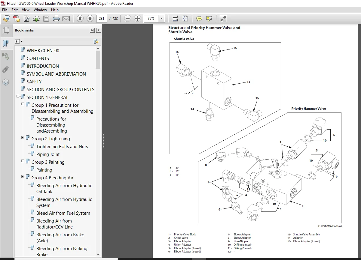
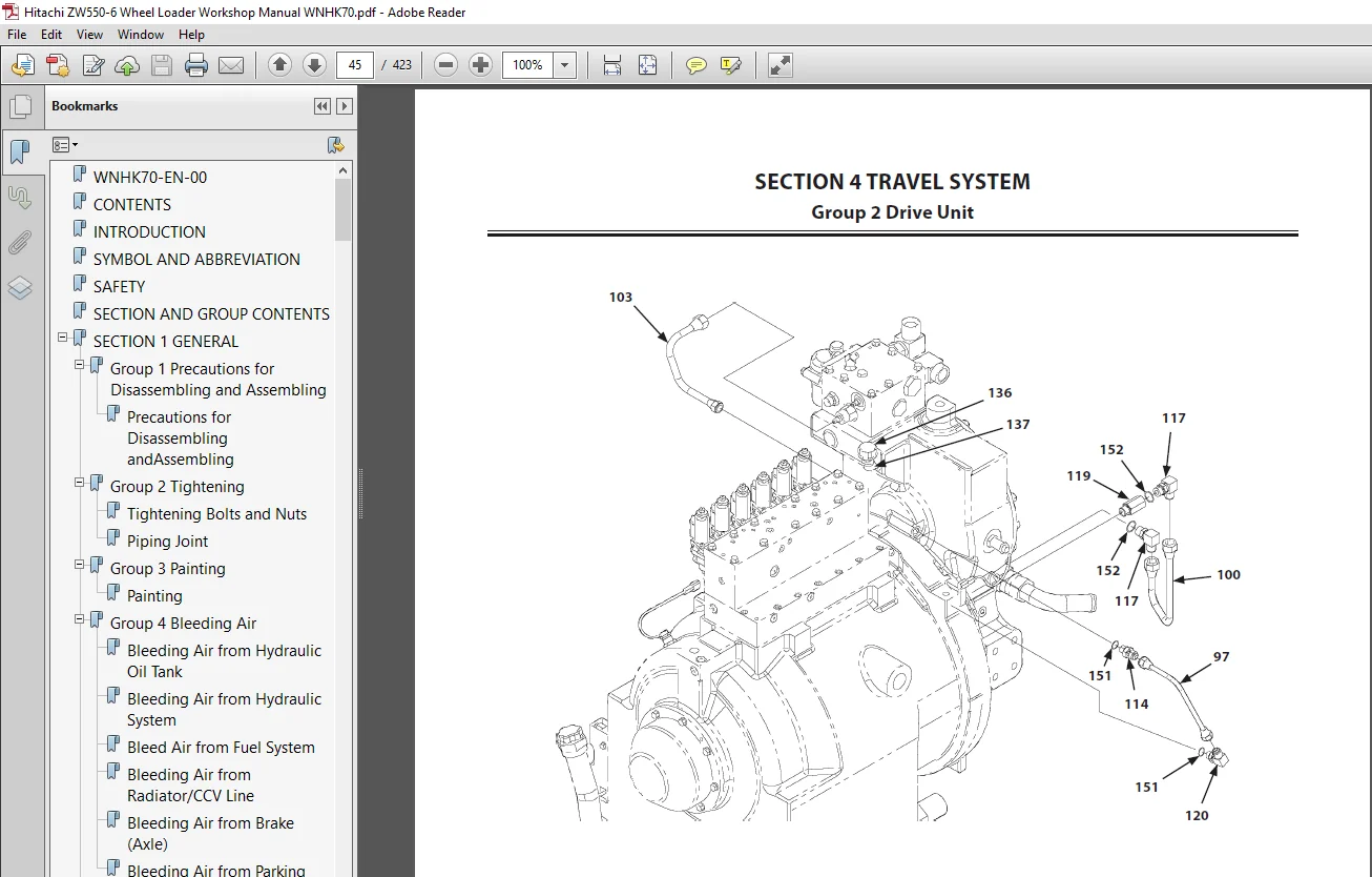
WNHK70-EN-00....................................................................  0
CONTENTS........................................................................  0
INTRODUCTION....................................................................  0
SYMBOL AND ABBREVIATION.........................................................  0
SAFETY..........................................................................  0
SECTION AND GROUP CONTENTS......................................................  0
SECTION 1 GENERAL...............................................................  0
	Group 1 Precautions for Disassembling and Assembling........................  0
		Precautions for Disassembling andAssembling.............................  0
	Group 2 Tightening..........................................................  0
		Tightening Bolts and Nuts...............................................  0
		Piping Joint............................................................  0
	Group 3 Painting............................................................  0
		Painting................................................................  0
	Group 4 Bleeding Air........................................................  0
		Bleeding Air from Hydraulic Oil Tank....................................  0
		Bleeding Air from Hydraulic System......................................  0
		Bleed Air from Fuel System..............................................  0
		Bleeding Air from Radiator/CCV Line.....................................  0
		Bleeding Air from Brake (Axle)..........................................  0
		Bleeding Air from Parking Brake.........................................  0
	Group 5 Pressure Release Procedure..........................................  0
		Front Attachment Hydraulic Circuit PressureRelease Procedure............  0
		Ride Control Accumulator Pressure ReleaseProcedure......................  0
		Parking Brake Accumulator Pressure ReleaseProcedure.....................  0
	Group 6 Preparation.........................................................  0
		Preparation before Inspection andMaintenance............................  0
SECTION 2 MAINTENANCE STANDARD..................................................  0
	Group 1 Body................................................................  0
		Center Hinge............................................................  0
		Pilot Valve (Two Lever Type)............................................  0
	Group 2 Front Attachment....................................................  0
		Pin and Bushing.........................................................  0
		Standard Dimensions for Lift Arm and Bucket.............................  0
SECTION 3 BODY..................................................................  0
	Group 1 Cab.................................................................  0
		Removal and Installation of Cab.........................................  0
	Group 2 Counterweight.......................................................  0
		Removal and Installation of Counterweight...............................  0
	Group 3 Center Hinge........................................................  0
		Removal and Installation of Center Hinge................................  0
		Removal and Installation of the HydraulicHoses of Front Frame Side......  0
	Group 4 Engine..............................................................  0
		Removal and Installation of Engine......................................  0
		Removal and Installation of Exterior Parts..............................  0
		Removal and Installation of Air Cleaner.................................  0
	Group 5 Radiator Assembly...................................................  0
		Replacement of Radiator and Cooling System..............................  0
	Group 6 Hydraulic Oil Tank..................................................  0
		Removal and Installation of Hydraulic Oil Tank..........................  0
	Group 7 Fuel Tank...........................................................  0
		Removal and Installation of Fuel Tank...................................  0
	Group 8 Pump Device.........................................................  0
		Removal and Installation of Pump Device.................................  0
		Disassembly and Assembly of Pump Device.................................  0
		Disassembly of Main Pump................................................  0
		Assembly of Main Pump...................................................  0
		Disassembly of Regulator................................................  0
		Assembly of Regulator...................................................  0
		Removal and Installation of Pilot Pump..................................  0
		Disassembly of Pilot Pump...............................................  0
		Assembly of Pilot Pump..................................................  0
	Group 9 Control Valve.......................................................  0
		Removal and Installation of Control Valve...............................  0
		Disassembly and Assembly of Control Valve...............................  0
	Group 10 Pilot Valve........................................................  0
		Removal and Installation of Pilot Valve(Single Lever Type)..............  0
		Removal and Installation of Pilot Valve (TwoLever Type )................  0
		Disassembly of Pilot Valve (Single LeverType)...........................  0
		Assembly of Pilot Valve (Single Lever Type).............................  0
		Disassembly of Pilot Valve (Two Lever Type).............................  0
		Assembly of Pilot Valve (Two Lever Type)................................  0
	Group 11 Brake Charge Valve.................................................  0
		Removal and Installation of Brake ChargeValve...........................  0
		Structure of Brake Charge Valve.........................................  0
		Disassembly of Brake Charge Valve.......................................  0
		Assembly of Brake Charge Valve..........................................  0
		Removal and Installation of BrakeAccumulators...........................  0
	Group 12 Combination Valve..................................................  0
		Removal and Installation of CombinationValve............................  0
		Structure and Tightening Torque of Combination Valve Components.........  0
	Group 13 DEF Tank...........................................................  0
		Removal and Installation of DEF Tank....................................  0
		Disassembly of DEF Tank.................................................  0
		Assembly of DEF Tank....................................................  0
	Group 14 Flow Regulator Valve...............................................  0
		Removal and Installation of Flow RegulatorValve.........................  0
		Structure of Flow Regulator Valve.......................................  0
	Group 15 Cooling Fan System.................................................  0
		Removal and Installation of Fan ControlValve............................  0
		Disassembly and Assembly of Fan ControlValve............................  0
		Removal and Installation of Fan Motor...................................  0
		Structure of Fan Motor..................................................  0
		Removal and Installation of Pilot Pump..................................  0
	Group 16 Aftertreatment Device..............................................  0
		Removal and Installation of AftertreatmentDevice........................  0
	Group 17 Ride Control Valve and Accumulator.................................  0
		Removal and Installation of Ride ControlValve and Accumulator...........  0
		Disassembly of Ride Control Valve.......................................  0
		Assembly of Ride Control Valve..........................................  0
	Group 18 Battery Disconnect Switch..........................................  0
		Removal of Battery Disconnect Switch....................................  0
		Installation of Battery Disconnect Switch...............................  0
		Structure of Battery Box Mount..........................................  0
SECTION 4 TRAVEL SYSTEM.........................................................  1
	Group 1 Tire................................................................  3
		Removal and Installation of Front Tire..................................  3
		Removal and Installation of Rear Tire...................................  5
	Group 2 Drive Unit.......................................................... 11
		Removal and Installation of Torque Converter............................ 11
		Disassembly and Assembly of TorqueConverter............................. 15
		Disassembly and Assembly of Torque ConverterSub Assembly................ 24
		Removal and Installation of Transmission................................ 31
		Disassembly and Assembly of Transmission Assy........................... 41
		Disassembly and Assembly of Clutch Assembly............................. 63
		Disassembly and Assembly of Low and ThirdSpeed Clutch Assembly.......... 78
		Disassembly and Assembly of Second SpeedClutch Assembly................. 81
		Disassembly and Assembly of Reverse ClutchAssembly...................... 84
		Disassembly and Assembly of First ClutchAssembly........................ 87
		Disassembly and Assembly of High ClutchSpider Assembly.................. 93
		Disassembly and Assembly of Gear Box Assembly........................... 99
		Removal and Installation of TransmissionControl Valve...................103
		Disassembly and Assembly of Transmission Control Valve..................107
		Special Tools (For Transmission Assembly and Disassembly)...............109
		Drawings for Special Tools..............................................110
	Group 3 Axle................................................................115
		Removal and Installation of Front Axle..................................115
		Removal and Installation of Rear Axle...................................121
		Disassembly of Axle.....................................................129
		Assembly of Axle........................................................137
		Disassembly and Assembly of Spider Assembly.............................148
		Disassembly and Assembly of Internal GearHub Assembly...................150
		Removal and Installation of Floating Seal...............................154
		Removal and Installation of Differential................................157
		Disassembly and Assembly of Differential................................163
		Disassembly and Assembly of Parking BrakePiston Assembly................185
		Special Tools For Axle Assembly.........................................187
		Drawings for Special Tools..............................................188
	Group 4 Propeller Shaft.....................................................195
		Removal and Installation of Propeller Shaft.............................195
	Group 5 Brake Valve.........................................................207
		Removal and Installation of Brake Valve.................................207
		Disassembly and Assembly of Brake ValveAssembly.........................211
		Disassembly and Assembly of Brake Valve.................................217
		Maintenance Standard....................................................221
	Group 7 Steering Valve......................................................223
		Removal and Installation of Steering Valve..............................223
		Disassembly of Steering Valve...........................................227
		Assembly of Steering Valve..............................................230
	Group 8 Steering Cylinder...................................................233
		Removal and Installation of Steering Cylinder...........................233
		Disassembly of Steering Cylinder........................................239
		Assembly of Steering Cylinder...........................................242
		Removal and Installation of SteeringAccumulator.........................247
		Tools for Steering Cylinder Disassembly andAssembly.....................249
	Group 9 Emergency Steering Device...........................................253
		Removal and Installation of EmergencySteering Pump......................253
	Group 10 Reducing Valve.....................................................261
		Removal and Installation of Reducing Valve..............................261
		Disassembly of Reducing Valve...........................................263
		Assembly of Reducing Valve..............................................265
	Group 11 Stop Valve.........................................................267
		Removal and Installation of Stop Valve..................................267
		Disassembly of Stop Valve...............................................271
		Assembly of Stop Valve..................................................272
	Group 12 Main Pressure Block................................................273
		Removal and Installation of Main Pressure Block.........................273
		Structure of Main Pressure Block........................................275
	Group 13 Priority Hammer Valve and Shuttle Valve............................277
		Removal and Installation of Priority HammerValve and Shuttle Valve......277
		Structure of Priority Hammer Valve andShuttle Valve.....................281
	Group 14 Check Valve........................................................283
		Removal and Installation of Check Valve.................................283
		Structure of Check Valve................................................285
	Group 15 Joystick Steering..................................................287
		Removal and Installation of Joystick SteeringValve (with Sears Seat)....287
		Disassembly and Assembly of JoystickSteering Valves.....................293
		Removal and Installation of Joystick SteeringLever (with Sears Seat)....301
		Disassembly of Joystick Steering Pilot Valve(for Hydraulic Type JSS)....309
		Assembly of Joystick Steering Pilot Valve...............................313
	Group 16 Axle Oil Cooler....................................................319
		Removal and Installation of Axle Oil Cooler.............................319
		Structure of Oil Cooler Assembly........................................331
		Structure of Oil Cooler Pump Unit.......................................334
SECTION 5 FRONT ATTACHMENT......................................................339
	Group 1 Front Attachment....................................................341
		Removal and Installation of Front Attachment............................341
		Removal and Installation of Lever (Bell Crank)..........................355
		Removal and Installation of Bucket......................................369
	Group 2 Cylinder............................................................377
		Removal and Installation of Lift Arm Cylinder...........................377
		Removal and Installation of Bucket Cylinder.............................385
		Disassembly of Lift Arm Cylinder........................................397
		Assembly of Lift Arm Cylinder...........................................401
		Disassembly of Bucket Cylinder..........................................407
		Assembly of Bucket Cylinder.............................................411
		Tools for Cylinder Disassembly and Assembly.............................417
SERVICE MANUAL REVISION REQUEST FORM............................................423
Please Note:
- This is the SAME exact manual used by your dealers to fix your vehicle.
- The same can be yours in the next 2-3 mins as you will be directed to the download page immediately after paying for the manual.
- Any queries / doubts regarding your purchase, please feel free to contact [email protected]