Trusted Business
Verified & Licensed
Virus Free Files
100% Safe Downloads
Secure Payment
SSL Protected
Instant Delivery
Available Immediately
Sale!

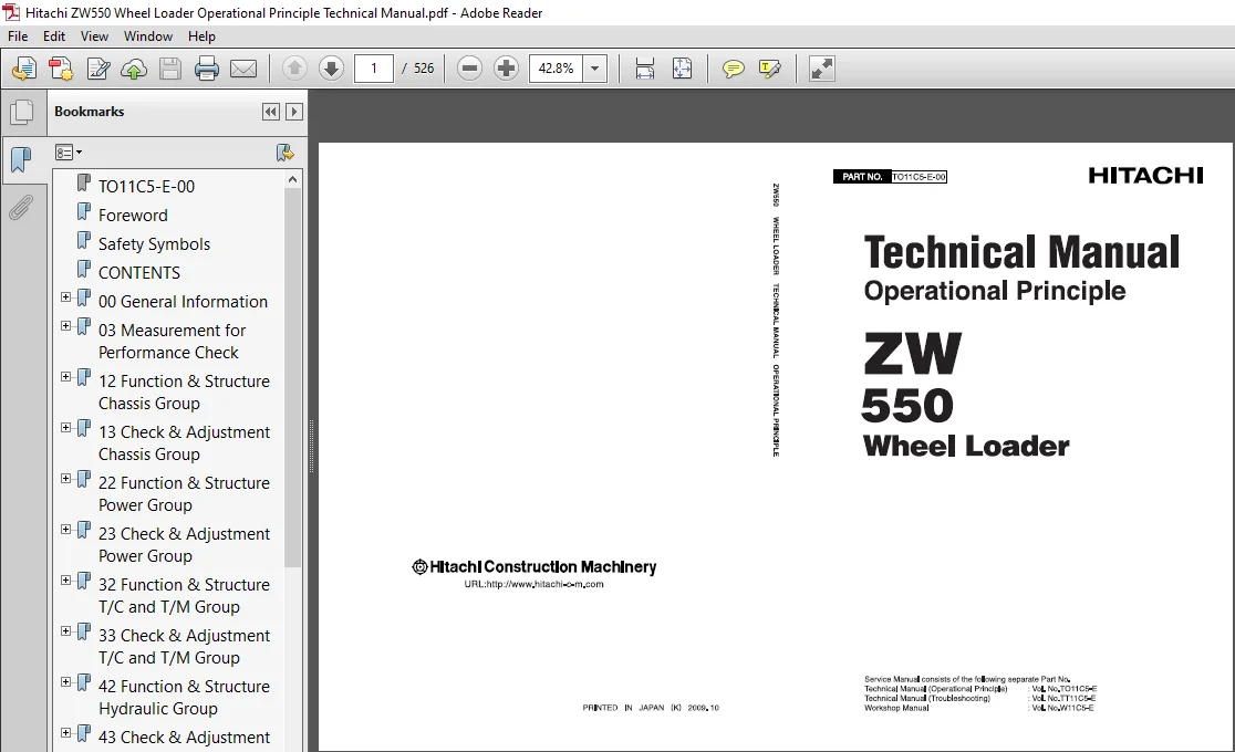
Hitachi ZW550 Wheel Loader Operational Principle Technical Manual (TO11C5-E-00) – PDF Download
Original price was: $78.95.$27.95Current price is: $27.95.
- Hitachi ZW550 Wheel Loader Operational Principle Technical Manual
- Part No:TO11C5-E-00
Instant PDF Download
Available immediately
Save to Your Device
Download & keep forever
Antivirus Scanned
100% virus-free
Trusted Worldwide
175,000+ customers
Description
Hitachi ZW550 Wheel Loader Operational Principle Technical Manual (TO11C5-E-00)
File Details:
Hitachi ZW550 Wheel Loader Operational Principle Technical Manual (TO11C5-E-00)
- Manual Language:English
- Pages: 526
- Size: 21.0 MB
- Downloadable:Yes
- Format:PDF
HITACHI ZW550 WHEEL LOADER OPERATIONAL PRINCIPLE TECHNICAL MANUAL (TO11C5-E-00) – PDF DOWNLOAD:
Image Preview:
Description:
Hitachi ZW550 Wheel Loader Operational Principle Technical Manual (TO11C5-E-00)
- To ensure good machine performance, reduce failures or problems, and prolong the service life of each component, it is necessary to operate the machine as is directed in the Operator and Maintenance Manual.
- To effectively diagnose and repair the machine, it is important to follow the guidelines laid out in this Technical Manual.
- For the engine, refer to the engine Shop Manual provided by the engine manufacturer.
- The purpose of this manual is to provide information on the product and the correct maintenance and repair methods. Please read this manual to ensure correct troubleshooting and good repair service.
- This manual will be periodically reviewed and revised for more satisfactory content. If you have any opinion or requests, please inform us.
Table Of Contents:
Hitachi ZW550 Wheel Loader Operational Principle Technical Manual (TO11C5-E-00)
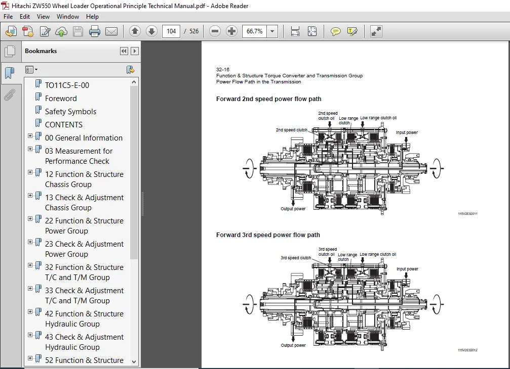
TO11C5-E-00.......................................................................................  1
Foreword..........................................................................................  3
Safety Symbols....................................................................................  4
CONTENTS..........................................................................................  5
00 General Information............................................................................ 17
	How to Use Manual............................................................................. 18
		Safety precautions........................................................................ 18
		Symbols................................................................................... 19
	Outline....................................................................................... 20
		Layout of main components................................................................. 20
		Inspection and maintenance table.......................................................... 21
		Recommended lubricants.................................................................... 24
		Coolant................................................................................... 25
			Coolant specification................................................................. 25
			Recommended mixture of antifreeze..................................................... 25
		Lubrication chart......................................................................... 26
		Weight of main components................................................................. 27
		Bolt tightening torque.................................................................... 28
			Hexagon bolt.......................................................................... 28
			Flanged hexagon bolt.................................................................. 31
		Hose band tightening torque............................................................... 32
		Liquid gasket and screw lock agent........................................................ 33
			Cautions regarding parts removal...................................................... 33
			Cautions regarding reassembly......................................................... 33
			Screw lock agent application procedure................................................ 34
			How to wind a seal tape............................................................... 34
		Cautions regarding welding repair service................................................. 35
03 Measurement for Performance Check.............................................................. 37
	Cautions on Safety............................................................................ 38
	Standard Measurement Values for Performance Check............................................. 39
12 Function & Structure Chassis Group............................................................. 43
	Front Chassis................................................................................. 44
		Loading linkage........................................................................... 44
		Loading linkage pin....................................................................... 46
	Rear Chassis.................................................................................. 47
		Fuel tank................................................................................. 47
		Floor board mount......................................................................... 48
			Floor board........................................................................... 48
			Viscous mount......................................................................... 48
	Center Pin.................................................................................... 49
		Upper center pin.......................................................................... 49
		Lower center pin.......................................................................... 50
		Dust seal................................................................................. 51
13 Check & Adjustment Chassis Group............................................................... 53
	Linkage Pin................................................................................... 54
		Liner..................................................................................... 54
			Bucket hinge pin section (#1)......................................................... 55
			How to assemble....................................................................... 55
			Bucket link pin section (#2).......................................................... 56
			How to assemble....................................................................... 56
			Adjustment............................................................................ 57
	Center Pin.................................................................................... 58
		Adjusting shim............................................................................ 58
		Installing bearing cover.................................................................. 58
		Installing bearing outer ring............................................................. 59
22 Function & Structure Power Group............................................................... 61
	Power Line.................................................................................... 62
	Engine / Transmission......................................................................... 63
		Engine / transmission mount............................................................... 63
	Radiator...................................................................................... 64
		Radiator mount............................................................................ 65
	Propeller Shaft............................................................................... 66
		First propeller shaft assembly............................................................ 67
			Transmission - Torque converter....................................................... 67
		Second propeller shaft assembly........................................................... 68
			Front differential - Transmission..................................................... 68
		Third propeller shaft assembly............................................................ 69
			Transmission - Rear differential...................................................... 69
	Axle Assembly................................................................................. 70
	Axle Support.................................................................................. 72
	Differential Gear............................................................................. 74
		Conventional type......................................................................... 74
		Function of differential gear............................................................. 77
			Power transmission.................................................................... 77
		Operation of differential gear............................................................ 77
			Straight.............................................................................. 77
			Turn.................................................................................. 78
23 Check & Adjustment Power Group................................................................. 79
	Engine........................................................................................ 80
		Measuring engine speed.................................................................... 80
		Measuring engine oil pressure............................................................. 80
	Propeller Shaft............................................................................... 81
		Propeller shaft phase..................................................................... 81
		Second propeller shaft alignment.......................................................... 81
		Propeller shaft tightening torque......................................................... 82
	Axle.......................................................................................... 83
		Axle nut tightening procedure............................................................. 83
		Differential gear adjustment procedure.................................................... 84
			Preload adjustment.................................................................... 85
			Bearing installation.................................................................. 86
			Oil seal installation................................................................. 86
			Adjusting tooth contact............................................................... 87
32 Function & Structure T/C and T/M Group......................................................... 89
	Torque Converter.............................................................................. 90
		Torque converter structure................................................................ 91
		Power flow path........................................................................... 91
		Torque multiplication..................................................................... 91
	Torque Converter (Lock-up) (Option)........................................................... 92
		Lock-up clutch structure.................................................................. 93
		Lock-up clutch function (only forward).................................................... 93
			Automatic shift (with lock-up solenoid)............................................... 94
	Torque Converter Gear Pump.................................................................... 95
		Gear pump specifications.................................................................. 95
	Transmission.................................................................................. 96
		Clutch combination........................................................................ 97
		Planetary gear............................................................................ 97
		Shift lever position...................................................................... 97
		Downshift button operation................................................................ 97
		Gear train and number of teeth............................................................ 98
			Clutch specifications................................................................. 98
			Friction plate: mm (in)............................................................... 99
			Steel plate: mm (in)..................................................................100
	Clutch Pack...................................................................................102
	Power Flow Path in the Transmission...........................................................103
		Forward 1st speed power flow path.........................................................103
		Forward 2nd speed power flow path.........................................................104
		Forward 3rd speed power flow path.........................................................104
		Forward 4th speed power flow path.........................................................105
		Reverse 1st speed power flow path.........................................................105
		Reverse 2nd speed power flow path.........................................................106
		Reverse 3rd speed power flow path.........................................................106
	Hydraulic System Diagram......................................................................107
	Hydraulic Circuit Diagram.....................................................................108
	Oil Flow......................................................................................110
		Oil flow in the torque converter line.....................................................110
		Oil flow in the transmission line.........................................................110
	T/C and T/M Oil Circulation...................................................................112
	Modulator Valve Unit..........................................................................113
		Interior schematic (not exact representation).............................................115
		Modulation Mechanism......................................................................116
			Modulator valve function..............................................................116
		Modulator valve operation.................................................................117
	Control Valve Assembly........................................................................119
		Clutch solenoid valve assembly............................................................121
			For high, low, reverse and speed clutches.............................................123
		Clutch valve assembly.....................................................................124
		Accumulator assembly......................................................................125
			Accumulator structure.................................................................125
		Direct charge valve.......................................................................126
		Lock-up clutch solenoid valve.............................................................127
33 Check & Adjustment T/C and T/M Group...........................................................129
	Clutch Oil Pressure and Time Lag..............................................................130
		Measuring clutch oil pressure.............................................................130
			Clutch oil pressure measurement procedure.............................................131
			Time lag measurement procedure........................................................132
42 Function & Structure Hydraulic Group...........................................................133
	Flushing Hydraulic Circuit....................................................................134
		Purpose of flushing.......................................................................134
	Cautions on Hydraulic Parts Replacement.......................................................135
	Hydraulic Circuit Symbols.....................................................................136
		Hydraulic lines...........................................................................136
		Pumps & motors............................................................................136
		Cylinders.................................................................................136
		Operation methods.........................................................................137
		Pressure control valve....................................................................137
		Flow control valve........................................................................137
		Directional control valve.................................................................138
		Check valve...............................................................................138
		Miscellaneous hydraulic symbols...........................................................139
	Hydraulic System Operation....................................................................140
		Hydraulic system operation outline........................................................140
			Loading system........................................................................140
			Steering system.......................................................................140
			Efficient loading system..............................................................141
			Fan motor system......................................................................141
			Ride control system (OPT).............................................................141
	Layout of Hydraulic Units.....................................................................142
	Hydraulic Tank................................................................................143
		Hydraulic tank breather valve (tank cap)..................................................144
		Hydraulic tank specifications.............................................................145
		Hydraulic oil level check.................................................................146
	Hydraulic Pump................................................................................147
		Loading and pilot and brake pump..........................................................147
		Pump specifications.......................................................................147
		Steering pump.............................................................................148
		Steering pump specifications..............................................................148
		Hydraulic pump principle..................................................................149
		Hydraulic pump wear plate.................................................................150
		Hydraulic pump bushing lubrication........................................................150
	Hydraulic Cylinder............................................................................151
		Boom cylinder.............................................................................151
		Bucket cylinder...........................................................................151
		Steering cylinder.........................................................................152
		Hydraulic cylinder specifications.........................................................153
	Loading System................................................................................154
	Reducing Valve (for Pilot Pressure)...........................................................155
	Pilot Valve...................................................................................156
		Pilot valve function......................................................................158
		Pilot valve operation (modulated position)................................................158
		Pre-detent and detent magnet solenoid.....................................................160
	Multiple Control Valve (KML35A/2T103).........................................................161
		Multiple control valve specifications.....................................................162
		Multiple control valve main relief valve..................................................163
			Main relief valve operation...........................................................163
			Adjusting set pressure................................................................164
		Multiple control valve overload relief valve (with make-up function)......................165
			Overload relief valve operation.......................................................165
			Make-up valve operation...............................................................166
		Multiple control valve make-up valve......................................................166
			Make-up valve operation...............................................................166
		Multiple control valve bucket spool.......................................................167
			Bucket spool operation................................................................167
		Multiple control valve boom spool.........................................................169
			Boom spool operation..................................................................169
	Adapter (Orifice).............................................................................172
	Ride Control (OPT)............................................................................173
		Ride control hydraulic circuit............................................................173
			Ride control function.................................................................173
		Ride control operation....................................................................174
			Preparation mode (ride control switch is OFF).........................................174
			Running mode (ride control switch is ON)..............................................175
		Ride control valve assembly (Reducing valve circuit)......................................176
			Reducing valve........................................................................177
			Check valve...........................................................................177
			Solenoid valve........................................................................178
		Ride control valve assembly (Accumulator circuit).........................................179
			Shuttle valve.........................................................................180
			Solenoid valve........................................................................180
			Selector valve........................................................................181
		Accumulator (for ride control)............................................................182
			Accumulator function..................................................................182
	Steering System...............................................................................183
	Orbitrol®.....................................................................................184
		Orbitrol® structure.......................................................................184
			Valve part............................................................................184
			Rotor part............................................................................185
		Orbitrol® specifications..................................................................185
		Orbitrol® operation.......................................................................186
			Neutral...............................................................................186
			Turn..................................................................................187
		Orbitrol® feed-back mechanism operation...................................................188
		Steering speed and flow rate control......................................................189
		Hydraulic pump oil amount and steering force..............................................189
		Orbit rotor operation principle...........................................................190
	Steering Valve (KVS32-A4.0/21)................................................................191
		Steering valve operation..................................................................193
			Neutral position (steering spool in "Neutral")........................................193
			Left turn position....................................................................194
		Steering spool variable throttle..........................................................195
		Steering valve flow control spool.........................................................196
		Steering valve main relief valve..........................................................197
			When the pressure is at the preset value or less......................................197
			When the pressure exceeds the preset value............................................198
		Steering valve overload relief valve......................................................199
			Overload relief valve operation.......................................................200
			Make-up valve operation...............................................................200
		Steering pilot circuit and its operation..................................................201
			Flow amplifier notch and pilot orifice................................................202
	Stop Valve....................................................................................203
		Stop valve function.......................................................................204
		Stop valve operation......................................................................204
	Reducing Valve (for Orbitrol®)................................................................205
	Steering Line Filter..........................................................................206
	Efficient Loading System......................................................................207
		Efficient loading system outline..........................................................207
			The operation condition of ELS........................................................207
		Mounting of the ELS valve.................................................................208
		Mounting of the variable kickout sensor...................................................209
		Efficient loading system operation........................................................210
			While the ELS is not operating........................................................210
			While the ELS is operating............................................................210
	Fan Motor System..............................................................................211
		Mounting of fan motor.....................................................................211
	Fan Motor Line................................................................................212
		Hydraulic circuit (fan motor normal rotation).............................................214
			Make-up valve.........................................................................214
		Proportional relief valve (S/N 9001~9050).................................................216
			Proportional relief valve operation...................................................216
		Proportional relief valve (S/N 9051~).....................................................218
	Reversing Fan Motor Line (OPT)................................................................223
		Reversing fan motor function..............................................................223
			Reversing fan motor (OPT).............................................................224
			Fan motor specifications..............................................................224
			Reversing fan control chart...........................................................226
		Hydraulic circuit (Reverse rotation)......................................................227
	Secondary Steering............................................................................228
		Secondary steering circuit................................................................228
			Secondary steering operation..........................................................229
			Secondary steering motor and pump.....................................................230
43 Check & Adjustment Hydraulic Group.............................................................231
	Loading/Steering Circuit Relief Valve/Ride Control Circuit Reducing Valve (OPT)...............232
		Loading circuit relief valve setting pressures............................................232
			Measuring loading circuit main relief pressure........................................233
			Measuring loading circuit overload relief pressure....................................235
			Measuring pilot circuit reducing valve pressure.......................................236
		Ride control circuit reducing valve setting pressures (OPT)...............................237
			Measuring ride control circuit reducing pressure......................................238
		Steering circuit relief valve setting pressures...........................................240
			Measuring steering circuit main relief pressure.......................................241
			Measuring steering circuit overload relief pressure...................................242
			Measuring pilot circuit relief pressure (reducing pressure)...........................243
	Hydraulic Cylinder............................................................................245
		Cylinder natural drift....................................................................245
	Stop Valve....................................................................................247
		Stop valve adjustment procedure...........................................................247
52 Function & Structure Brake Group...............................................................249
	Brake System Outline..........................................................................250
		Service brake.............................................................................250
		Parking brake.............................................................................250
		Adjustment of axle internal pressure......................................................250
	Brake Units Layout............................................................................251
	Unloader Valve................................................................................252
		Unloader valve operation..................................................................254
	Valve Unit....................................................................................255
		Accumulator low pressure sensor...........................................................256
	Accumulator...................................................................................257
	Brake Valve...................................................................................258
		Brake valve performance chart.............................................................259
		Brake valve outline.......................................................................260
			While the valve is not operating......................................................260
	Service Brake.................................................................................262
		Service brake operation...................................................................262
		Service brake friction disc...............................................................263
		Service brake steel plate.................................................................264
		Service brake piston......................................................................265
		Service brake pedal stroke adjusting mechanism............................................266
			Tolerance ring........................................................................267
		Brake circuit air bleeding procedure......................................................268
			Bleeding air from brake pipes and axle housing hubs...................................269
			Bleeding air from parking brake housing...............................................269
	Parking Brake.................................................................................270
		Parking brake operation...................................................................273
			Operation of parking brake............................................................273
		Parking brake friction disc...............................................................276
		Parking brake steel plate.................................................................276
		Parking brake solenoid valve..............................................................277
			Solenoid valve operation..............................................................277
			Solenoid valve specifications.........................................................277
	Parking Brake Manual Release..................................................................278
	Brake Circuit Check Valve.....................................................................280
	Auto Brake....................................................................................281
		Auto brake circuit........................................................................281
		Auto brake operation set value............................................................281
		Reducing valve (for Autobrake circuit)....................................................282
		Solenoid valve (for Autobrake circuit)....................................................283
			Solenoid specifications...............................................................283
	Pressure Sensor (for stop lamp and declutch)..................................................284
		Pressure sensor (for stop lamp)...........................................................284
		Pressure sensor (for Declutch)............................................................285
53 Check & Adjustment Brake Group.................................................................287
	Brake Circuit Oil Pressure....................................................................288
		Unloader valve setting pressure...........................................................288
			Unloader valve setting pressure measurement...........................................289
		Brake valve oil pressure..................................................................290
			Brake valve oil pressure measurement..................................................290
			Brake valve performance...............................................................291
	Service Brake.................................................................................292
		Service brake performance check...........................................................292
		Service brake friction plate wear measurement.............................................293
		Cautions on installing brake discs........................................................294
	Parking Brake.................................................................................295
		Parking brake performance check...........................................................295
62 Function & Structure Electrical Group..........................................................297
	How to Use Electrical Wiring Diagram..........................................................298
		Utilisation des schémas des câblages électriques (FRANÇAIS)...............................299
		Verwendung des elektrischen Schaltplans (DEUTSCH).........................................300
		Modalità di utilizzo dello schema dei collegamenti elettrici (ITALIANO)...................301
		Cómo utilizar un Diagrama de Alambrado Eléctrico (ESPAÑOL)................................302
		Como Utilizar o Diagrama de Ligações Eléctricas (PORTUGUÊS)...............................303
	Electrical Cable Color Codes..................................................................304
	Electrical Circuit Symbols....................................................................305
	Sensor Mount..................................................................................306
	Fuse..........................................................................................307
		Fuse box..................................................................................307
		Fusible link..............................................................................308
	Engine Start Circuit..........................................................................309
		Engine start circuit diagram..............................................................309
		Neutral starter...........................................................................310
			Shift lever neutral (N) position......................................................310
			Shift lever forward/reverse (F/R) position............................................310
		Starter switch............................................................................311
			ECM safety features...................................................................312
		Battery relay.............................................................................312
			Battery relay operation...............................................................312
		Alternator I terminal wire................................................................313
		Diode unit................................................................................313
		Neutral relay.............................................................................314
		Magnetic switch...........................................................................315
		Voltage relay.............................................................................316
	Power Generating/Charging Circuit.............................................................317
		Alternator................................................................................317
	ECM (Engine Controller).......................................................................318
		Function of ECM...........................................................................318
		Connection diagram........................................................................318
		Monitor lamp test.........................................................................319
		Failure diagnosis.........................................................................320
			Engine diagnostic switch (option).....................................................320
			Failure diagnostic chart..............................................................321
			Increment decrement switch (option)...................................................322
		Quantum fault code information............................................................323
		Accelerator pedal.........................................................................329
			Accelerator pedal installation........................................................330
	Transmission Control Circuit and Monitor Circuit..............................................331
		Machine control unit (MCU)................................................................331
			Connector.............................................................................332
		MCU connection diagram....................................................................333
		Machine control unit (MCU) function.......................................................335
			Forward/reverse (F/R) shifting and speed change.......................................335
			Automatic shift.......................................................................337
			Automatic shift (with lock-up solenoid)...............................................338
			Machine speed sensor..................................................................339
			Downshift button operation............................................................340
			Modulation at clutch switching........................................................341
		Modulator valve operation.................................................................342
		Adjustable declutch preset switch.........................................................343
			Back-up alarm.........................................................................344
			Parking brake.........................................................................345
			Auto brake............................................................................347
			Machine control unit (MCU) failure warning............................................350
			Secondary steering function (OPT).....................................................351
		Monitoring system.........................................................................353
			Items to be monitored and operation condition.........................................353
		Operation monitor lamps...................................................................355
	Instrument Panel and Switch...................................................................356
		Instrument panel..........................................................................356
		Instrument panel rear surface.............................................................357
		Gauge circuit.............................................................................358
		Fuel gauge circuit........................................................................360
	MODM..........................................................................................361
		MODM function.............................................................................361
		Monitor Changeover........................................................................361
			Changing display from one function to next............................................362
		Information Monitor.......................................................................364
			Information monitor display...........................................................364
			Unit conversion and language selection................................................367
		Replacement Monitor.......................................................................368
			Replacement time check................................................................368
			Replacement interval set (timer reset)................................................372
			Replacement interval pop-up...........................................................373
			Display language......................................................................374
		Fault Log Monitor.........................................................................374
			Fault log history check...............................................................374
			Selection of machine fault log and engine fault log...................................375
			Machine fault log navigation..........................................................376
			Engine fault log navigation...........................................................376
			Clear fault log.......................................................................376
			Clear active fault log (error pop up).................................................377
		Input/Output Monitor......................................................................381
			Input/Output monitor display..........................................................381
		Parameter Setting Monitor.................................................................385
			Parameter setting monitor display.....................................................385
			Parameter change......................................................................393
		Specification Setting Monitor.............................................................394
			Specification setting monitor display.................................................394
			All setting reset.....................................................................397
	Electrical Detent Circuit.....................................................................400
		Bucket leveler............................................................................400
			Proximity switch......................................................................400
		Detent solenoid...........................................................................401
		Lift kickout & lower kickout..............................................................402
			Location..............................................................................402
			Lift kickout..........................................................................402
			Lower kickout.........................................................................402
		Sensor assy...............................................................................403
		Detent solenoid...........................................................................405
		Preset height adjustment..................................................................405
	Diode.........................................................................................406
		Diode check method........................................................................407
		Caution for diode check method............................................................407
			Continuity check mode.................................................................407
			Diode check mode......................................................................407
			Resistance check mode.................................................................408
		Surge voltage and surge suppression diodes................................................409
72 Function & Structure Operator Station Group....................................................411
	Cabin.........................................................................................412
		Glass.....................................................................................414
			1. Part number 32011-21690............................................................415
			2. Part number 32011-21700............................................................415
			3. Part number 32011-21500............................................................416
		Wiper mount...............................................................................417
			Front wiper...........................................................................417
			Rear wiper............................................................................417
		Wiper motor...............................................................................418
	Operator Seat.................................................................................420
	Steering and Transmission Shift Lever.........................................................421
		Tilt case.................................................................................422
		Column shaft..............................................................................423
		Shift lever...............................................................................423
	Air Conditioner...............................................................................424
		Air conditioner components................................................................424
			Air conditioner specifications (system performance)...................................424
		Denso air conditioner structure...........................................................425
			Cooling unit..........................................................................425
			Heater and accessories................................................................427
			Air distributor (hood & defroster selection box)......................................427
			Air compressor (with magnetic clutch).................................................428
			Condenser unit........................................................................428
			Control unit..........................................................................429
		Function of cooling mechanism.............................................................430
			Principle of cooling..................................................................430
			Refrigerant...........................................................................431
			Refrigerant characteristics...........................................................432
		Cooling circuit...........................................................................433
		Electrical circuit........................................................................434
			Control schematic drawing.............................................................434
		Air conditioner functions of components...................................................435
			Control panel.........................................................................435
			Air conditioner unit..................................................................442
			Compressor and magnetic clutch........................................................451
			Condenser unit........................................................................454
			Receiver dryer........................................................................456
			Sight glass...........................................................................458
			Pressure switches.....................................................................458
			Pressure relief valve.................................................................460
			Relay A...............................................................................461
			Relay B...............................................................................461
			Refrigerant hose......................................................................462
		Charge of refrigerant.....................................................................463
			Work procedure........................................................................464
			Refrigerant charging tools............................................................466
			Refrigerant charging procedure........................................................469
			Troubleshooting using the gauge manifold..............................................475
	Troubleshooting...............................................................................480
		Air conditioner...........................................................................480
73 Check & Adjustment Operator Station Group......................................................489
	Air Conditioner...............................................................................490
		Adjustment of lubricating oil quantity when components of air conditioner are replaced....490
			When the compressor is replaced.......................................................491
			When the evaporator is replaced.......................................................492
			When the condenser is replaced........................................................492
		Adjustment of air gap (between hub and rotor) in compressor magnetic clutch...............493
		Compressor V-belt adjustment..............................................................494
			Belt adjustment procedure.............................................................494
			Belt adjustment value.................................................................494
		Parts to be replaced periodically.........................................................495
			Air filters...........................................................................495
			Receiver dryer........................................................................495
Function & Structure Supplement...................................................................497
	Foreword......................................................................................498
	01 Function & Structure Supplement............................................................497
		Quick Coupler.............................................................................499
			Hydraulic line and electrical circuit.................................................499
			Solenoid valve........................................................................501
				Solenoid valve specifications.....................................................502
		Power boost circuit.......................................................................503
			Multiple control valve main relief valve (MRV) (2 stage relief).......................505
				Multiple control valve main relief valve(MRV) operation...........................506
				Multiple control valve main relief valve(MRV) adjusting set pressure..............506
				Measuring loading circuit overload reliefpressure.................................507
				Adjusting overload relief pressure................................................507
			Hydraulic line........................................................................508
			Electrical cable......................................................................509
				Electrical connection diagram.....................................................510
		Short Boom (OPT)..........................................................................511
			Bucket cylinder.......................................................................512
				Bucket cylinder specifications....................................................512
		Limited Slip Differential (LSD)...........................................................513
			LSD gear structure....................................................................513
			LSD function..........................................................................517
			LSD operation.........................................................................517
Maintenance Log...................................................................................519
Notes.............................................................................................523
Please Note:
⦁ This is not a physical manual but a digital manual – meaning no physical copy will be couriered to you. The manual can be yours in the next 2 mins as once you make the payment, you will be directed to the download page IMMEDIATELY.
⦁ This is the same manual used by the dealers inorder to diagnose your vehicle of its faults.
⦁ Require some other service manual or have any queries: please WRITE to us at [email protected]