Trusted Business
Verified & Licensed
Virus Free Files
100% Safe Downloads
Secure Payment
SSL Protected
Instant Delivery
Available Immediately
Sale!


HITACHI ZX 160LC-5A HYDRAULIC EXCAVATOR WORKSHOP MANUAL + TROUBLESHOOTING + OPERATIONAL PRINCIPLE + ELECTRICAL-HYDRAULIC CIRCUIT DIAGRAM – DOWNLOAD
Original price was: $79.00.$39.95Current price is: $39.95.
HITACHI ZX 160LC-5A HYDRAULIC EXCAVATOR WORKSHOP MANUAL + TROUBLESHOOTING + OPERATIONAL PRINCIPLE + ELECTRICAL-HYDRAULIC CIRCUIT DIAGRAM – DOWNLOAD
Instant PDF Download
Available immediately
Save to Your Device
Download & keep forever
Antivirus Scanned
100% virus-free
Trusted Worldwide
175,000+ customers
Description
HITACHI ZX 160LC-5A HYDRAULIC EXCAVATOR WORKSHOP MANUAL + TROUBLESHOOTING + OPERATIONAL PRINCIPLE + ELECTRICAL-HYDRAULIC CIRCUIT DIAGRAM – DOWNLOAD
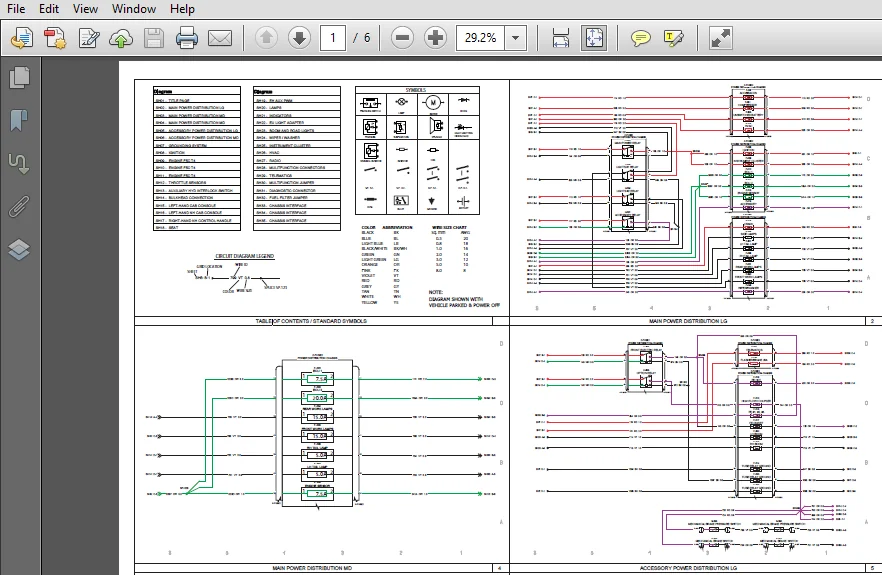
SCREENSHOTS FROM THE MANUAL:
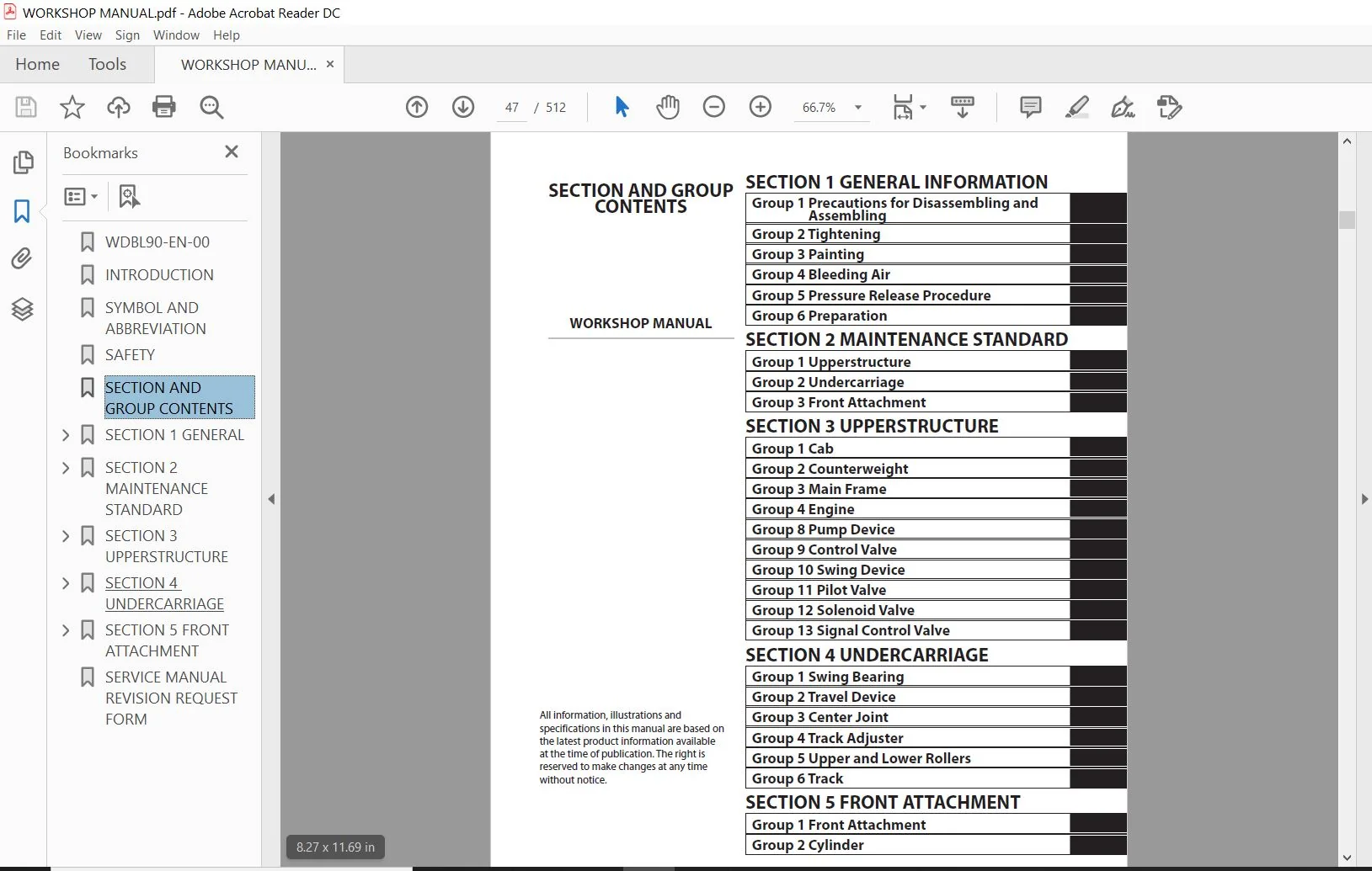
WORKSHOP MANUAL TABLE OF CONTENTS :
HITACHI ZX 160LC-5A HYDRAULIC EXCAVATOR WORKSHOP MANUAL + TROUBLESHOOTING + OPERATIONAL PRINCIPLE + ELECTRICAL-HYDRAULIC CIRCUIT DIAGRAM – DOWNLOAD
WDBL90-EN-00.........................................................  1
INTRODUCTION.........................................................  3
SYMBOL AND ABBREVIATION..............................................  5
SAFETY...............................................................  7
SECTION AND GROUP CONTENTS........................................... 47
SECTION 1 GENERAL.................................................... 49
	Group 1 Precautions for Disassembling and Assembling............. 51
		Precautions for Disassembling and Assembling................. 51
	Group 2 Tightening............................................... 57
		Tightening Bolts and Nuts.................................... 57
		Piping Joint................................................. 60
	Group 3 Painting................................................. 65
		Painting..................................................... 65
	Group 4 Bleeding Air............................................. 67
		Bleeding Air from Hydraulic Oil Tank......................... 67
		Bleeding Air from Hydraulic System........................... 68
		Bleeding Air from Fuel System................................ 69
		Bleeding Air from Radiator................................... 71
	Group 5 Pressure Release Procedure............................... 73
		Hydraulic Circuit Pressure Release Procedure................. 73
	Group 6 Preparation.............................................. 75
		Preparation before Inspection and Maintenance................ 75
SECTION 2 MAINTENANCE STANDARD....................................... 79
	Group 1 Upperstructure........................................... 81
		Pump Device.................................................. 81
		Swing Motor.................................................. 85
	Group 2 Undercarriage............................................ 89
		Travel Motor................................................. 89
		Sprocket..................................................... 91
		Front Idler.................................................. 93
		Upper Roller................................................. 95
		Lower Roller................................................. 96
		Track........................................................ 97
	Group 3 Front Attachment.........................................101
		Pin and Bushing..............................................101
		Side Cutter (2015428, 2015429)...............................103
		Point (963228)...............................................104
		Standard Dimensions for Arm and Bucket Connection............105
		Standard Dimensions for Arm and Boom Connection..............106
		Cylinder.....................................................107
SECTION 3 UPPERSTRUCTURE.............................................111
	Group 1 Cab......................................................113
		Removal and Installation of Cab..............................113
		Dimensions of Cab Glass......................................141
	Group 2 Counterweight............................................161
		Removal and Installation of Counterweight....................161
	Group 3 Main Frame...............................................163
		Removal and Installation of Main Frame.......................163
	Group 4 Engine...................................................173
		Removal and Installation of Engine...........................173
	Group 8 Pump Device..............................................199
		Removal and Installation of Pump Device......................199
		Removal and Installation of Coupling.........................209
		Disassembly of Pump Device...................................211
		Assembly of Pump Device......................................218
		Disassembly of Regulator.....................................229
		Assembly of Regulator........................................231
		Disassembly of Solenoid Valve................................233
		Assembly of Solenoid Valve...................................235
		Structure of Pilot Pump......................................237
	Group 9 Control Valve............................................239
		Removal and Installation of Control Valve....................239
		Disassembly of Housing.......................................259
		Assembly of Housing..........................................261
		Disassembly of Control Valve (4-Spool Side)..................263
		Assembly of Control Valve (4-Spool Side).....................270
		Disassembly of Control Valve (5-Spool Side)..................281
		Assembly of Control Valve (5-Spool Side).....................288
	Group 10 Swing Device............................................297
		Removal and Installation of Swing Device.....................297
		Disassembly of Swing Device..................................301
		Assembly of Swing Device.....................................306
		Disassembly of Swing Motor...................................313
		Assembly of Swing Motor......................................316
	Group 11 Pilot Valve.............................................319
		Removal and Installation of Pilot Valve (Left)...............319
		Removal and Installation of Pilot Valve(Right)...............325
		Removal and Installation of Travel Pilot Valve...............333
		Disassembly of Pilot Valves (Right and Left).................337
		Assembly of Pilot Valves (Right and Left)....................340
		Disassembly of Travel Pilot Valve............................343
		Assembly of Travel Pilot Valve...............................347
	Group 12 Solenoid Valve..........................................353
		Removal and Installation of Pilot Shut-Off Solenoid Valve....353
		Removal and Installation of 3-Spool Solenoid Valve Unit......357
		Disassembly of Pilot Shut-Off Solenoid Valve.................361
		Assembly of Pilot Shut-Off Solenoid Valve....................363
		Structure of 3-Spool Solenoid Valve Unit.....................365
	Group 13 Signal Control Valve....................................367
		Removal and Installation of Signal Control Valve.............367
		Structure of Signal Control Valve............................373
SECTION 4 UNDERCARRIAGE..............................................377
	Group 1 Swing Bearing............................................379
		Removal and Installation of Swing Bearing....................379
		Disassembly of Swing Bearing.................................383
		Assembly of Swing Bearing....................................386
	Group 2 Travel Device............................................389
		Removal and Installation of Travel Device....................389
		Disassembly of Travel Device.................................393
		Assembly of Travel Device....................................397
		Disassembly of Travel Motor..................................405
		Assembly of Travel Motor.....................................408
		Disassembly of Brake Valve...................................413
		Assembly of Brake Valve......................................415
		Precautions for Using Floating Seal..........................417
	Group 3 Center Joint.............................................419
		Removal and Installation of Center Joint.....................419
		Disassembly of Center Joint..................................423
		Assembly of Center Joint.....................................425
		Replacement of Body and Spindle..............................428
	Group 4 Track Adjuster...........................................429
		Removal and Installation of Track Adjuster...................429
		Disassembly of Front Idler...................................433
		Assembly of Front Idler......................................436
		Disassembly of Track Adjuster................................439
		Assembly of Track Adjuster...................................443
		Precautions for Using Floating Seal..........................447
	Group 5 Upper and Lower Rollers..................................449
		Removal and Installation of Upper Roller.....................449
		Removal and Installation of Lower Roller.....................453
		Disassembly of Lower Roller..................................459
		Assembly of Lower Roller.....................................461
		Precautions for Using Floating Seal..........................463
	Group 6 Track....................................................465
		Removal and Installation of Track............................465
SECTION 5 FRONT ATTACHMENT...........................................473
	Group 1 Front Attachment.........................................475
		Removal and Installation of Front Attachment.................475
	Group 2 Cylinder.................................................483
		Removal and Installation of Boom Cylinder....................483
		Removal and Installation of Arm Cylinder.....................487
		Removal and Installation of Bucket Cylinder..................493
		Disassembly of Boom, Arm, and Bucket Cylinders...............497
		Assembly of Boom, Arm, and Bucket Cylinders..................504
SERVICE MANUAL REVISION REQUEST FORM.................................511

OPERATORS MANUAL - TABLE OF CONTENTS:
TTDBL90-EN-00.............................................................................................  1
INTRODUCTION..............................................................................................  3
SYMBOL AND ABBREVIATION...................................................................................  5
SAFETY....................................................................................................  7
SECTION AND GROUP CONTENTS................................................................................ 47
SECTION 4
OPERATIONAL PERFORMANCE TEST.................................................................... 49
	Group 1 Introduction.................................................................................. 51
		Operational Performance Tests..................................................................... 51
		Preparation for Performance Tests................................................................. 52
	Group 2 Standard...................................................................................... 53
		Operational Performance Standard Table............................................................ 53
		Main Pump P-Q Diagram............................................................................. 61
		Sensor Activating Range........................................................................... 63
		MPDr. Monitor Indicating Values................................................................... 64
	Group 3 Engine Test................................................................................... 77
		Engine Speed...................................................................................... 77
		Lubricant Consumption............................................................................. 80
	Group 4 Machine Performance Test...................................................................... 81
		Travel Speed...................................................................................... 81
		Track Revolution Speed............................................................................ 82
		Mistrack Check.................................................................................... 83
		Travel Parking Leakage............................................................................ 84
		Swing Speed....................................................................................... 85
		Swing Function Drift Check........................................................................ 86
		Swing Motor Leakage............................................................................... 88
		Maximum Swingable Slant Angle..................................................................... 90
		Swing Bearing Play................................................................................ 92
		Hydraulic Cylinder Cycle Time..................................................................... 94
		Dig Function Drift Check.......................................................................... 96
		Control Lever Operating Force..................................................................... 99
		Control Lever Stroke..............................................................................100
		Combined Operation of Boom Raise/Swing Function Check.............................................101
		Combined Operation of Boom Raise/Arm Roll-In Function Check.......................................102
		Clearance of Front Attachment Connecting Part.....................................................103
	Group 5 Component Test................................................................................105
		Primary Pilot Pressure............................................................................105
		Secondary Pilot Pressure..........................................................................107
		3-Spool Solenoid Valve Set Pressure...............................................................108
		Main Pump Delivery Pressure.......................................................................111
		Main Relief Set Pressure..........................................................................112
		Relief Pressure (when relieving swing)............................................................116
		Overload Relief Valve Set Pressure................................................................118
		Main Pump Flow Rate Measurement...................................................................120
		Swing Motor Drainage..............................................................................128
		Travel Motor Drainage.............................................................................130
SECTION 5
TROUBLESHOOTING.................................................................................135
	Group 1 Diagnosing Procedure..........................................................................137
		Introduction......................................................................................137
		Diagnosis Procedure...............................................................................138
		Electric System Inspection........................................................................141
		Precautions for Inspection and Maintenance........................................................142
		Instructions for Disconnecting Connectors.........................................................144
		Fuse Inspection...................................................................................146
		Fusible Link Inspection...........................................................................149
		Battery Voltage Check.............................................................................150
		Alternator Check..................................................................................151
		Continuity Check..................................................................................152
		Voltage and Current Measurement...................................................................154
		Check by False Signal.............................................................................161
		Test Harness......................................................................................162
	Group 2 Monitor.......................................................................................165
		Outline...........................................................................................165
		Operating Procedures of Service Menu..............................................................166
		Setting Menu......................................................................................203
		Inspection of Engine Oil Level, Coolant Level, Hour Meter, and Fuel Gauge.........................206
		Fuel Gauge and Coolant Temperature Gauge..........................................................207
	Group 3 e-Service.....................................................................................209
		Outline...........................................................................................209
		List of Operation Data............................................................................210
		Snapshot Data.....................................................................................214
		Communication System..............................................................................215
	Group 4 Component Layout..............................................................................217
		Main Component....................................................................................217
		Electrical System (Overview)......................................................................218
		Electrical System (Rear Tray).....................................................................219
		Electrical System (Switch Panel)..................................................................220
		Electrical System (Around Air Cleaner)............................................................221
		Electrical System (Relays, etc.)..................................................................222
		Components Related with Engine....................................................................223
		Components Related with Pump Device...............................................................224
		Around Pump Device................................................................................225
		Components Related with Control Valve.............................................................226
		Components Related with Control Valve.............................................................226
		Components Related with Swing Device..............................................................228
		Travel Device.....................................................................................228
		3-Spool Solenoid Valve Unit.......................................................................229
		Layout of Attachment Spec. Parts..................................................................230
		Boom Foot Part Lower Side.........................................................................231
		Components in Control Valve.......................................................................234
		Pilot Port........................................................................................254
	Group 5 Troubleshooting A.............................................................................259
		Troubleshooting A (Base Machine Diagnosis
By Using Fault Codes) Procedure.........................259
		MC Fault Code List................................................................................261
		ECM Fault Code List...............................................................................272
		Monitor Controller (Monitor) Fault Code List......................................................296
		Monitor Controller (Information) Fault Code List..................................................297
		Air Conditioner Controller Fault Code List........................................................300
		Communication Terminal Fault Code List............................................................301
		MC Fault Codes 11000 to 11002.....................................................................303
		MC Fault Code 11003...............................................................................304
		MC Fault Codes 11006, 11007,11009
Monitor Controller (Monitor) Fault Codes 13002, 13003, 13005....306
		CAN0 Harness Check................................................................................307
		MC Fault Codes 11008, 11010
Monitor Controller (Monitor) Fault Codes 13004, 13006, 13007..........311
		CAN1 Harness Check................................................................................312
		MC Fault Code 11100...............................................................................315
		MC Fault Code 11101...............................................................................316
		MC Fault Codes 11200, 11202.......................................................................317
		MC Fault Codes 11206, 11208.......................................................................318
		MC Fault Codes 11301 to 11303.....................................................................319
		MC Fault Codes 11304, 11307.......................................................................320
		MC Fault Codes 11325, 11997.......................................................................321
		MC Fault Code 11410...............................................................................322
		MC Fault Code 11400...............................................................................323
		MC Fault Code 11401...............................................................................324
		MC Fault Code 11402...............................................................................325
		MC Fault Code 11403...............................................................................326
		MC Fault Code 11407...............................................................................327
		MC Fault Code 11436...............................................................................328
		MC Fault Codes 11458, 11459.......................................................................329
		MC Fault Code 11901...............................................................................330
		MC Fault Code 20011...............................................................................331
		MC Fault Code 20062...............................................................................332
		Monitor Controller (Information) Fault Codes 13304, 13310.........................................333
		Monitor Controller (Information) Fault Code 13311.................................................334
		Air Conditioner Controller Fault Codes 11 to 22...................................................335
		Air Conditioner Controller Fault Codes 43 to 92...................................................336
		Monitor Controller (Information) Fault Codes 20100 to 20114.......................................337
		Monitor Controller (Information) Fault Codes 20109 to 20149.......................................338
	Group 6 Troubleshooting B.............................................................................339
		Troubleshooting B (Machine Diagnosis by
Using Troubleshooting Symptom) Procedure..................339
		Relationship between Machine Trouble
Symptoms and Related Parts...................................341
		Correlation between Trouble Symptoms and Part Failures............................................361
		Engine System Troubleshooting.....................................................................375
		All Actuator System Troubleshooting...............................................................383
		Front Attachment System Troubleshooting...........................................................390
		Swing System Troubleshooting......................................................................402
		Travel System Troubleshooting.....................................................................404
		Other System Troubleshooting......................................................................409
		Exchange Inspection...............................................................................414
		How to Lowering Boom in Case of Emergency and When Engine Stops...................................417
	Group 7 Air Conditioner...............................................................................419
		Outline...........................................................................................419
		Functions of Main Parts...........................................................................422
		Troubleshooting...................................................................................427
		Air Conditioner Controller Fault Code List........................................................428
		Air Conditioner Controller Fault Codes 11 to 22...................................................429
		Air Conditioner Controller Fault Codes 43 to 92...................................................430
		Work after Replacing Components...................................................................452
		Refill Compressor Oil.............................................................................453
		Charge Air Conditioner with Refrigerant...........................................................454
		Hose and Pipe Tightening Torque...................................................................462
SERVICE MANUAL REVISION REQUEST FORM......................................................................465
The Attached Diagram List.................................................................................466
TODBL90-EN-00..............................................................................................................................................................  1
INTRODUCTION...............................................................................................................................................................  3
SYMBOL AND ABBREVIATION....................................................................................................................................................  5
SECTION AND GROUP CONTENTS.................................................................................................................................................  7
SECTION 1
GENERAL..........................................................................................................................................................  9
	Group 1 Specifications................................................................................................................................................. 11
		Specifications..................................................................................................................................................... 11
		Working Ranges (Grouser shoe)...................................................................................................................................... 12
	Group 2 Component Layout............................................................................................................................................... 13
		Main Component..................................................................................................................................................... 13
		Electrical System (Overview)....................................................................................................................................... 14
		Electrical System (Rear Tray)...................................................................................................................................... 15
		Electrical System (Switch Panel)................................................................................................................................... 16
		Electrical System (Around Air Cleaner)............................................................................................................................. 17
		Electrical System (Relays, etc.)................................................................................................................................... 18
		Components Related with Engine..................................................................................................................................... 19
		Components Related with Pump Device................................................................................................................................ 20
		Around Pump Device................................................................................................................................................. 21
		Components Related with Control Valve.............................................................................................................................. 22
		Components Related with Control Valve.............................................................................................................................. 22
		Components Related with Swing Device............................................................................................................................... 24
		Travel Device...................................................................................................................................................... 24
		3-Spool Solenoid Valve Unit........................................................................................................................................ 25
		Layout of Attachment Spec. Parts................................................................................................................................... 26
		Boom Foot Part Lower Side.......................................................................................................................................... 27
	Group 3 Component Specifications....................................................................................................................................... 29
		Engine............................................................................................................................................................. 29
		Engine Accessories................................................................................................................................................. 33
		Hydraulic Component................................................................................................................................................ 34
		Electrical Component............................................................................................................................................... 38
SECTION 2
SYSTEM........................................................................................................................................................... 41
	Group 1 Controller..................................................................................................................................................... 43
		Outline............................................................................................................................................................ 43
		CAN Circuit........................................................................................................................................................ 44
	Group 2 Control System................................................................................................................................................. 47
		Outline............................................................................................................................................................ 47
		Engine Control..................................................................................................................................................... 50
		Pump Control....................................................................................................................................................... 82
		Valve Control (Standard)........................................................................................................................................... 96
		Valve Control (Optional)...........................................................................................................................................108
		Other Control......................................................................................................................................................116
	Group 3 ECM System.....................................................................................................................................................125
		Outline............................................................................................................................................................125
		Fuel Injection Control.............................................................................................................................................126
		Fuel Injection Amount Correction Control...........................................................................................................................134
		EGR Control........................................................................................................................................................136
		Preheating Control.................................................................................................................................................138
		Alarm Control......................................................................................................................................................139
	Group 4 Hydraulic System...............................................................................................................................................141
		Outline............................................................................................................................................................141
		Pilot Circuit......................................................................................................................................................142
		Main Circuit.......................................................................................................................................................152
		Breaker/Pulverizer/Crusher Circuit (Optional)......................................................................................................................168
	Group 5 Electrical System..............................................................................................................................................177
		Outline............................................................................................................................................................177
		Main Circuit.......................................................................................................................................................178
		Electric Power Circuit (Key Switch: OFF)...........................................................................................................................180
		CAN Circuit........................................................................................................................................................182
		Accessory Circuit..................................................................................................................................................184
		Starting Circuit (Key Switch: START)...............................................................................................................................186
		Charging Circuit (Key Switch: ON)..................................................................................................................................188
		Surge Voltage Prevention Circuit...................................................................................................................................192
		Pilot Shut-Off Circuit (Key switch: ON)............................................................................................................................194
		Auto Shut-Down Circuit/Automatic Engine Stop Circuit at Low Temperature............................................................................................196
		Engine Stop Circuit................................................................................................................................................198
		Monitor Circuit....................................................................................................................................................201
		Security Circuit...................................................................................................................................................202
		Radio Circuit......................................................................................................................................................204
		Air Conditioner Circuit............................................................................................................................................204
		Accessory Circuit..................................................................................................................................................207
		Work Light Circuit.................................................................................................................................................208
		Wiper/Washer Circuit...............................................................................................................................................210
		Cab Light Circuit..................................................................................................................................................212
SECTION 3
COMPONENT OPERATION..............................................................................................................................................217
	Group 1 Pump Device....................................................................................................................................................219
		Outline............................................................................................................................................................219
		Main Pump..........................................................................................................................................................220
		Regulator..........................................................................................................................................................224
		Solenoid Valve.....................................................................................................................................................242
		Pilot Pump.........................................................................................................................................................244
		Pump Delivery Pressure Sensor......................................................................................................................................244
		Pump Control Pressure Sensor.......................................................................................................................................244
	Group 2 Swing Device...................................................................................................................................................245
		Outline............................................................................................................................................................245
		Swing Reduction Gear...............................................................................................................................................246
		Swing Motor........................................................................................................................................................247
		Swing Parking Brake................................................................................................................................................248
		Valve Unit.........................................................................................................................................................250
	Group 3 Control Valve..................................................................................................................................................253
		Outline............................................................................................................................................................253
		Hydraulic Circuit..................................................................................................................................................274
		Flow Combiner Valve................................................................................................................................................280
		Main Relief Valve..................................................................................................................................................282
		Overload Relief Valve (with Make-Up Function)......................................................................................................................286
		Regenerative Valve.................................................................................................................................................290
		Anti-Drift Valve...................................................................................................................................................294
		Flow Rate Control Valve............................................................................................................................................298
		Digging Regenerative Valve.........................................................................................................................................302
		Boom Lower Meter-In Cut Valve......................................................................................................................................304
		Auxiliary Flow Combiner Valve and Bypass Shut-Out Valve............................................................................................................306
	Group 4 Pilot Valve....................................................................................................................................................311
		Outline............................................................................................................................................................311
		Operation (Front Attachment / Swing and Travel Pilot Valves).......................................................................................................313
		Operation (Auxiliary Pilot Valve)..................................................................................................................................321
		Shockless Function (Only for Travel Pilot Valve)...................................................................................................................326
	Group 5 Travel Device..................................................................................................................................................327
		Outline............................................................................................................................................................327
		Travel Reduction Gear..............................................................................................................................................328
		Travel Motor.......................................................................................................................................................330
		Parking Brake......................................................................................................................................................332
		Travel Brake Valve.................................................................................................................................................334
		Overload Relief Valve..............................................................................................................................................338
		Travel Mode Control................................................................................................................................................340
	Group 6 Signal Control Valve...........................................................................................................................................345
		Outline............................................................................................................................................................345
		Pilot Port.........................................................................................................................................................346
		Shuttle Valve......................................................................................................................................................351
		Shockless Valve....................................................................................................................................................354
		Pump 1 and 2 Flow Rate Control Valve...............................................................................................................................358
		Bucket Flow Rate Control Valve Control Spool, Flow Combiner Valve Control Spool, Swing Parking Brake Release Spool, Arm 1 Flow Rate Control Valve Control Spool....360
	Group 7 Others (Upperstructure)........................................................................................................................................363
		Pilot Shut-Off Solenoid Valve......................................................................................................................................363
		Solenoid Valve.....................................................................................................................................................365
		Pilot Relief Valve.................................................................................................................................................369
		Recirculation Valve (Option).......................................................................................................................................370
	Group 8 Others (Undercarriage).........................................................................................................................................371
		Swing Bearing......................................................................................................................................................371
		Center Joint.......................................................................................................................................................372
		Track Adjuster (Front Idler Integrated Type).......................................................................................................................373
SERVICE MANUAL REVISION REQUEST FORM.......................................................................................................................................377
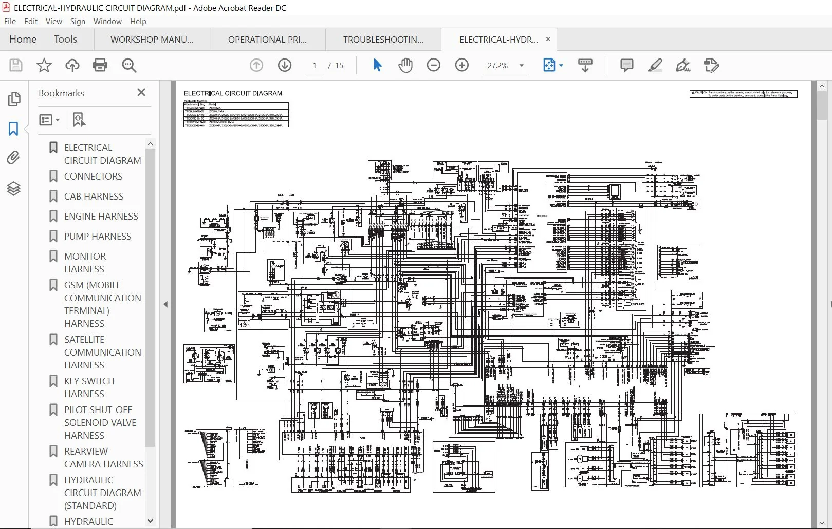
ELECTRICAL CIRCUIT DIAGRAM - TABLE OF CONTENTS:
ELECTRICAL CIRCUIT DIAGRAM..................... 1
CONNECTORS..................................... 2
CAB HARNESS.................................... 3
ENGINE HARNESS................................. 4
PUMP HARNESS................................... 5
MONITOR HARNESS................................ 6
GSM (MOBILE COMMUNICATION TERMINAL) HARNESS.... 7
SATELLITE COMMUNICATION HARNESS................ 8
KEY SWITCH HARNESS............................. 9
PILOT SHUT-OFF SOLENOID VALVE HARNESS..........10
REARVIEW CAMERA HARNESS........................11
HYDRAULIC CIRCUIT DIAGRAM (STANDARD)...........12
HYDRAULIC CIRCUIT DIAGRAM (OPTIONAL)...........13
AIR CONDITIONER CIRCUIT DIAGRAM................14
AIR CONDITIONER HARNESS........................15


TROUBLESHOOTING MANUAL - TABLE OF CONTENTS:
TODBL90-EN-00..............................................................................................................................................................  1
INTRODUCTION...............................................................................................................................................................  3
SYMBOL AND ABBREVIATION....................................................................................................................................................  5
SECTION AND GROUP CONTENTS.................................................................................................................................................  7
SECTION 1
GENERAL..........................................................................................................................................................  9
	Group 1 Specifications................................................................................................................................................. 11
		Specifications..................................................................................................................................................... 11
		Working Ranges (Grouser shoe)...................................................................................................................................... 12
	Group 2 Component Layout............................................................................................................................................... 13
		Main Component..................................................................................................................................................... 13
		Electrical System (Overview)....................................................................................................................................... 14
		Electrical System (Rear Tray)...................................................................................................................................... 15
		Electrical System (Switch Panel)................................................................................................................................... 16
		Electrical System (Around Air Cleaner)............................................................................................................................. 17
		Electrical System (Relays, etc.)................................................................................................................................... 18
		Components Related with Engine..................................................................................................................................... 19
		Components Related with Pump Device................................................................................................................................ 20
		Around Pump Device................................................................................................................................................. 21
		Components Related with Control Valve.............................................................................................................................. 22
		Components Related with Control Valve.............................................................................................................................. 22
		Components Related with Swing Device............................................................................................................................... 24
		Travel Device...................................................................................................................................................... 24
		3-Spool Solenoid Valve Unit........................................................................................................................................ 25
		Layout of Attachment Spec. Parts................................................................................................................................... 26
		Boom Foot Part Lower Side.......................................................................................................................................... 27
	Group 3 Component Specifications....................................................................................................................................... 29
		Engine............................................................................................................................................................. 29
		Engine Accessories................................................................................................................................................. 33
		Hydraulic Component................................................................................................................................................ 34
		Electrical Component............................................................................................................................................... 38
SECTION 2
SYSTEM........................................................................................................................................................... 41
	Group 1 Controller..................................................................................................................................................... 43
		Outline............................................................................................................................................................ 43
		CAN Circuit........................................................................................................................................................ 44
	Group 2 Control System................................................................................................................................................. 47
		Outline............................................................................................................................................................ 47
		Engine Control..................................................................................................................................................... 50
		Pump Control....................................................................................................................................................... 82
		Valve Control (Standard)........................................................................................................................................... 96
		Valve Control (Optional)...........................................................................................................................................108
		Other Control......................................................................................................................................................116
	Group 3 ECM System.....................................................................................................................................................125
		Outline............................................................................................................................................................125
		Fuel Injection Control.............................................................................................................................................126
		Fuel Injection Amount Correction Control...........................................................................................................................134
		EGR Control........................................................................................................................................................136
		Preheating Control.................................................................................................................................................138
		Alarm Control......................................................................................................................................................139
	Group 4 Hydraulic System...............................................................................................................................................141
		Outline............................................................................................................................................................141
		Pilot Circuit......................................................................................................................................................142
		Main Circuit.......................................................................................................................................................152
		Breaker/Pulverizer/Crusher Circuit (Optional)......................................................................................................................168
	Group 5 Electrical System..............................................................................................................................................177
		Outline............................................................................................................................................................177
		Main Circuit.......................................................................................................................................................178
		Electric Power Circuit (Key Switch: OFF)...........................................................................................................................180
		CAN Circuit........................................................................................................................................................182
		Accessory Circuit..................................................................................................................................................184
		Starting Circuit (Key Switch: START)...............................................................................................................................186
		Charging Circuit (Key Switch: ON)..................................................................................................................................188
		Surge Voltage Prevention Circuit...................................................................................................................................192
		Pilot Shut-Off Circuit (Key switch: ON)............................................................................................................................194
		Auto Shut-Down Circuit/Automatic Engine Stop Circuit at Low Temperature............................................................................................196
		Engine Stop Circuit................................................................................................................................................198
		Monitor Circuit....................................................................................................................................................201
		Security Circuit...................................................................................................................................................202
		Radio Circuit......................................................................................................................................................204
		Air Conditioner Circuit............................................................................................................................................204
		Accessory Circuit..................................................................................................................................................207
		Work Light Circuit.................................................................................................................................................208
		Wiper/Washer Circuit...............................................................................................................................................210
		Cab Light Circuit..................................................................................................................................................212
SECTION 3
COMPONENT OPERATION..............................................................................................................................................217
	Group 1 Pump Device....................................................................................................................................................219
		Outline............................................................................................................................................................219
		Main Pump..........................................................................................................................................................220
		Regulator..........................................................................................................................................................224
		Solenoid Valve.....................................................................................................................................................242
		Pilot Pump.........................................................................................................................................................244
		Pump Delivery Pressure Sensor......................................................................................................................................244
		Pump Control Pressure Sensor.......................................................................................................................................244
	Group 2 Swing Device...................................................................................................................................................245
		Outline............................................................................................................................................................245
		Swing Reduction Gear...............................................................................................................................................246
		Swing Motor........................................................................................................................................................247
		Swing Parking Brake................................................................................................................................................248
		Valve Unit.........................................................................................................................................................250
	Group 3 Control Valve..................................................................................................................................................253
		Outline............................................................................................................................................................253
		Hydraulic Circuit..................................................................................................................................................274
		Flow Combiner Valve................................................................................................................................................280
		Main Relief Valve..................................................................................................................................................282
		Overload Relief Valve (with Make-Up Function)......................................................................................................................286
		Regenerative Valve.................................................................................................................................................290
		Anti-Drift Valve...................................................................................................................................................294
		Flow Rate Control Valve............................................................................................................................................298
		Digging Regenerative Valve.........................................................................................................................................302
		Boom Lower Meter-In Cut Valve......................................................................................................................................304
		Auxiliary Flow Combiner Valve and Bypass Shut-Out Valve............................................................................................................306
	Group 4 Pilot Valve....................................................................................................................................................311
		Outline............................................................................................................................................................311
		Operation (Front Attachment / Swing and Travel Pilot Valves).......................................................................................................313
		Operation (Auxiliary Pilot Valve)..................................................................................................................................321
		Shockless Function (Only for Travel Pilot Valve)...................................................................................................................326
	Group 5 Travel Device..................................................................................................................................................327
		Outline............................................................................................................................................................327
		Travel Reduction Gear..............................................................................................................................................328
		Travel Motor.......................................................................................................................................................330
		Parking Brake......................................................................................................................................................332
		Travel Brake Valve.................................................................................................................................................334
		Overload Relief Valve..............................................................................................................................................338
		Travel Mode Control................................................................................................................................................340
	Group 6 Signal Control Valve...........................................................................................................................................345
		Outline............................................................................................................................................................345
		Pilot Port.........................................................................................................................................................346
		Shuttle Valve......................................................................................................................................................351
		Shockless Valve....................................................................................................................................................354
		Pump 1 and 2 Flow Rate Control Valve...............................................................................................................................358
		Bucket Flow Rate Control Valve Control Spool, Flow Combiner Valve Control Spool, Swing Parking Brake Release Spool, Arm 1 Flow Rate Control Valve Control Spool....360
	Group 7 Others (Upperstructure)........................................................................................................................................363
		Pilot Shut-Off Solenoid Valve......................................................................................................................................363
		Solenoid Valve.....................................................................................................................................................365
		Pilot Relief Valve.................................................................................................................................................369
		Recirculation Valve (Option).......................................................................................................................................370
	Group 8 Others (Undercarriage).........................................................................................................................................371
		Swing Bearing......................................................................................................................................................371
		Center Joint.......................................................................................................................................................372
		Track Adjuster (Front Idler Integrated Type).......................................................................................................................373
SERVICE MANUAL REVISION REQUEST FORM.......................................................................................................................................377


PLEASE NOTE:
This is the same manual used by the dealers to  diagnose and troubleshoot your vehicle
You will be directed to the download page as soon as the purchase is completed. The whole payment and downloading process will take anywhere between 2-5 minutes
Need any other service / repair / parts manual, please feel free to contact [email protected] . We still have 50,000 manuals unlisted