Hitachi ZX 250LC-7 250LCN-7 Hydraulic Excavator Operational Technical Manual PN:TODFY50 PDF
$29.95
Hitachi ZX 250LC-7 250LCN-7 Hydraulic Excavator Operational Technical Manual PN:TODFY50 – PDF DOWNLOAD
Service Manual consists of the following separate Part No.
Technical Manual (Operational Principle) : Vol. No.TODFY50-EN
Technical Manual (Troubleshooting) : Vol. No.TTDFY50-EN
Workshop Manual : Vol. No.WDFY50-EN
Engine Manual : Vol. No.ETDFY50-EN, EWDFY50-EN
Description
Hitachi ZX 250LC-7 250LCN-7 Hydraulic Excavator Operational Technical Manual PN:TODFY50 – PDF DOWNLOAD
FILE DETAILS:
Hitachi ZX 250LC-7 250LCN-7 Hydraulic Excavator Operational Technical Manual PN:TODFY50 – PDF DOWNLOAD
Language :English
Pages :479
Downloadable : Yes
File Type : PDF
IMAGES PREVIEW OF THE MANUAL:
DESCRIPTION:
Hitachi ZX 250LC-7 250LCN-7 Hydraulic Excavator Operational Technical Manual PN:TODFY50 – PDF DOWNLOAD
Service Manual consists of the following separate Part No.
Technical Manual (Operational Principle) : Vol. No.TODFY50-EN
Technical Manual (Troubleshooting) : Vol. No.TTDFY50-EN
Workshop Manual : Vol. No.WDFY50-EN
Engine Manual : Vol. No.ETDFY50-EN, EWDFY50-EN
To The Reader
This manual is written for an experienced technician to provide technical information needed to maintain and repair this machine.
- The machine specification and description according to destination may be explained on this manual.
- Be sure to thoroughly read this manual for correct product information and service procedures.
- If you have any questions or comments, at if you found any errors regarding the contents of this manual, please
- contact using “Service Manual Revision Request Form” at the end of this manual. (Note: Do not tear off the form. Copy this form for usage.)
Service Material Development Center Hitach Construction Machinery Co., Ltd.
Hitachi ZX 250LC-7 250LCN-7 Hydraulic Excavator Operational Technical Manual PN:TODFY50 – PDF DOWNLOAD
Service Manual consists of the following separate Part No.
Technical Manual (Operational Principle) : Vol. No.TODFY50-EN
Technical Manual (Troubleshooting) : Vol. No.TTDFY50-EN
Workshop Manual : Vol. No.WDFY50-EN
Engine Manual : Vol. No.ETDFY50-EN, EWDFY50-EN
TODFY50-EN-00 1
INTRODUCTION 3
To The Reader 3
Additional References 3
Manual Composition 3
Page Number 3
Trademark 4
Safety Alert Symbol and Headline Notations 4
Units Used 4
SYMBOL AND ABBREVIATION 7
Symbol and Abbreviation 7
CONTRASTING LIST OF PART NAME 9
Contrasting List of Part Name between Technical Manual and Parts Catalog 9
SECTION AND GROUP CONTENTS 11
CONTENTS 13
GENERAL 21
Specifications 23
Specifications of ZX250LC-7, 250LCN-7 23
Specifications of ZX250LC-7, 250LCN-7 (2-Piece Boom) 24
Working Ranges of ZX250LC-7, 250LCN-7 25
Working Ranges of ZX250LC-7, 250LCN-7 (2-Piece Boom) 26
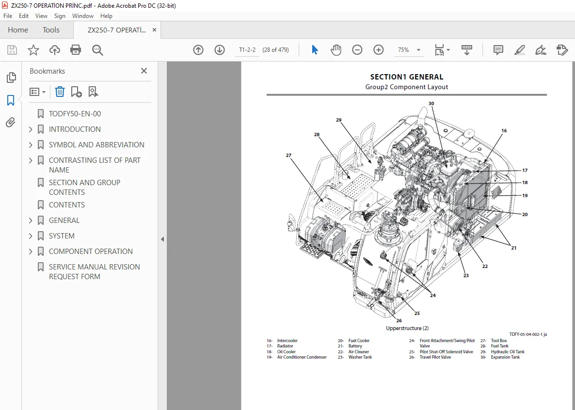
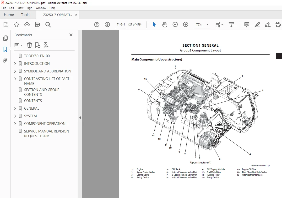
Component Layout 27
Main Component (Upperstructure) 27
Main Component (Undercarriage) 29
Main Component (Front Attachment) 29
Electrical System (Overview) 30
Electrical System (Rear Tray) 31
Electrical System (Switches) 32
Electrical System (Utility Space) 33
Electrical System (Relays) 33
Engine Oil Monitoring Sensor 34
Hydraulic Oil Monitoring Sensor 34
Engine 35
Aftertreatment Device 36
Pump Device 36
Around Pump Device 37
Control Valve 38
Signal Control Valve 38
Swing Device 39
Travel Device 40
5-Spool Solenoid Valve Unit 40
3-Spool Solenoid Valve Unit 41
2-Spool Solenoid Valve Unit (For Aftertreatment Device Regeneration Control) 41
DEF Tank 42
DEF Supply Module 42
Layout of Attachment Spec Parts 43
Around Control Valve 44
Control Valve Lower Side 44
Utility Space 45
Component Specifications 47
Specifications of Engine 47
Specifications of Engine Accessories 49
Specifications of Hydraulic Component 49
Specifications of Electrical Component 51
SYSTEM 53
Controller 55
Outline of Controller 55
CAN Circuit 55
Control System 57
Outline of Control System 57
Engine Control 57
Engine Control System Layout 58
Engine Protection Control 59
Engine Control Dial Control 61
ECO Control 63
Power Mode (ECO/PWR Mode) Switch Control 65
ECO Mode Control 67
Travel HP Mode Control 69
Auto-Idle Control 71
Hydraulic Oil Temperature Auto Warming-Up Control 73
Radiator Coolant Temperature Auto Warming-Up Control 75
Idle Speed-Up Control 77
Idle Speed-Up Control (Pilot Shut-Off Lever) 79
Engine Speed Slow Down Control 81
Heater Control 83
One-Touch Idle Control 85
Attachment Operation Speed Increase Control (Option) 87
Attachment Operation Speed Limit Control (Option) 89
Pump Control 91
Pump Control System Layout 92
Speed Sensing Control 93
Swing Relief Cut Control 95
Pump Torque Decrease Control (Radiator Coolant Temperature) 96
Pump Torque Decrease Control (Hydraulic Oil Temperature) 98
Travel Torque-Up Control 100
Pump Torque Restriction Control (During Engine Output Restriction) 102
Pump 1 Flow Rate Control 104
Pump 2 Flow Rate Control 106
Pump 3 Flow Rate Control 108
Pump 1 Flow Rate Limit Control (Option) 110
Pump 2 Flow Rate Limit Control (Option) 112
Pump 3 Flow Rate Limit Control (Option) 114
Valve Control (Standard) 116
Valve Control (Standard) System Layout 117
Power Digging Control 118
Auto-Power Lift Control 120
Travel Motor Displacement Angle Control 122
Arm Regenerative Cut Control 124
Digging Regenerative Control 126
Arm 1 Flow Rate Control 128
Arm 2 Roll-In Pilot Cut Control 130
Aftertreatment Device Manual Regeneration Control 132
Aftertreatment Device Auto Regeneration Control 134
Pump 3 Center Bypass Shut-Out Control 136
Arm Roll-In Meter-Out Open Control 138
Valve Control (Option) 141
Valve Control (Option) System Layout 142
Attachment Flow Rate Control 143
Auxiliary Flow Combiner Control 145
Breaker 1 (HSB Breaker) Control 147
Auxiliary Overload Relief Valve Pressure Control 149
Pump/Valve Coordination Control 151
Pump/Valve Coordination Control System Layout 152
Pump 3 Minimum Displacement Angle Hold Control during Digging Operation 153
Other Control 156
Work Mode Control 156
Auto Shut-Down Control 156
Automatic Engine Stop Control at Low Temperature 158
Hydraulic Oil Overheat Alarm Control 159
Breaker Alarm Control (Option) 160
Travel Alarm Control (Option) 161
Swing Alarm Control (Option) 162
Overload Alarm Control (Option) 164
Engine System 165
Outline of ECM System 165
Fuel Injection Control 166
Fuel Injection Amount Control 167
Fuel Injection Timing Control 169
Fuel Injection Rate Control 171
Fuel Injection Pressure Control 172
Fuel Injection Amount Correction Control 174
EGR Control 176
Preheating Control 178
Variable Turbocharger Control 179
Alarm Control 180
Urea SCR System 180
DEF Injection Control 181
Start-Up Control 182
DEF Defrosting Control(DEF Tank) 183
DEF Defrosting Control(DEF Piping) 184
DEF Thermal Control(DEF Tank) 185
DEF Thermal Control(DEF Piping) 186
After-Run Control 187
Engine Output Restriction Control (INDUCEMENT) 189
Insufficient DEF Level 190
Malfunction of Urea SCR System/Malfunction of EGR System 190
Outline of Aftertreatment Device 191
Operation of Aftertreatment Device 192
Aftertreatment Device Regeneration Control 193
Hydraulic System 197
Outline of Hydraulic System 197
Pilot Circuit of Hydraulic System 197
Operation Control Circuit 199
Pump Control Circuit (Refer to COMPONENT OPERATION/Pump Device ) 201
Aftertreatment Device Regeneration Control Circuit (Refer to SYSTEM/Control System ) 203
Valve Control Circuit (Refer to COMPONENT OPERATION/Control Valve, Travel Device ) 204
Travel Motor Displacement Angle Control Circuit (Refer to COMPONENT OPERATION/Travel Device ) 207
Swing Parking Brake Release Circuit (Refer to COMPONENT OPERATION/Swing Device ) 209
Main Circuit of Hydraulic System 209
Neutral Circuit 212
Flow Combiner Circuit (Front Attachment) 213
Relief Circuit 215
Combined Operation Circuit 217
Flow Combiner Circuit 218
Digging Regenerative Circuit 221
Arm Regenerative Cut Circuit 223
Arm 1 Flow Rate Control Circuit 225
Arm 2 Roll-In Pilot Cut Control Circuit 227
Pump 3 Center Bypass Shut-Out Control Circuit 229
Arm Roll-In Meter-Out Open Control Circuit 231
Bucket Regenerative Cut Circuit 233
Boom Lower Meter-In Cut Control 235
Boom Cylinder Bottom Pressure: High (With the Front Attachment above the Ground) 235
Boom Cylinder Bottom Pressure: Low (With the Track Raised off the Ground) 236
Pump 3 Minimum Displacement Angle Hold Control during Digging Operation Circuit 238
Breaker/Pulverizer/Crusher Circuit of Hydraulic System (Option) 239
Auxiliary Flow Combiner Circuit 241
When Performing Single Operation of Auxiliary Flow Combiner Circuit 241
When Performing Combined Operation of Auxiliary Flow Combiner Circuit 243
Breaker 1 (HSB Breaker) Circuit 245
Breaker 2 (NPK Breaker) Circuit 246
Electrical System 249
Outline of Electrical System 249
Main Circuit of Electrical System 249
Electric Power Circuit (Key Switch: OFF) 249
CAN Circuit 251
Accessory Circuit (Key Switch: ACC) 252
Starting Circuit (Key Switch: START) 253
Charging Circuit (Key Switch: ON) 255
Alternator Operation 256
Regulator Operation 257
Surge Voltage Prevention Circuit 257
Pilot Shut-Off Circuit (Key Switch: ON) 258
Auto Shut-Down Circuit/Automatic Engine Stop Circuit at Low Temperature 259
Engine Stop Circuit 261
Emergency Stop Circuit 262
Monitor Circuit of Electrical System 264
Security Circuit 265
Aerial Angle Circuit 266
Control Lever Automatic Pilot Shut-Off Circuit 266
Seat Belt Reminder Circuit 267
Radio Circuit 268
Air Conditioner Circuit 269
Accessory Circuit 270
Work Light Circuit (Work Light: ON) 270
Work Light Circuit (Work Light and Boom Light: ON) 272
Wiper Circuit 274
Washer Circuit 276
Cab Light Circuit (Cab Light Switch: Door Interlocking Position (Key Switch: ON)) 278
Cab Light Circuit (Cab Light Switch: ON Position) 279
COMPONENT OPERATION 281
Pump Device 285
Outline of Pump Device 285
Outline of Main Pump 286
Operational Principle of Main Pump 286
Increasing and Decreasing of Main Pump Delivery Flow Rate 287
Outline of Regulator 288
Regulator Control Function 290
Control by Pump Control Pressure 291
Control by Own and Partner Pump Delivery Pressure (Regulators for Pump 1 and Pump 2) 291
Control by Own Pump Delivery Pressure (Pump 3 Regulator) 292
Control by Pilot Pressure from Torque Control Solenoid Valves 293
Control by Pilot Pressure from Maximum Pump Flow Rate Limit Control Solenoid Valves (Pump Flow Rate Limit Control) 295
Control by Pilot Pressure from Maximum Pump Flow Rate Limit Control Solenoid Valves (Pump Flow Rate Control) 296
Flow Rate Increase Control by Pump Control Pressure 297
Flow Rate Decrease Control by Pump Control Pressure 300
Flow Rate Decrease Control by Own and Partner Pump Delivery Pressure (Regulators for Pump 1 and Pump 2) 303
Flow Rate Increase Control by Own and Partner Pump Delivery Pressure (Regulators for Pump 1 and Pump 2) 306
Flow Rate Decrease Control by Own Pump Delivery Pressure (Pump 3 Regulator) 309
Flow Rate Increase Control by Own Pump Delivery Pressure (Pump 3 Regulator) 312
Flow Rate Decrease Control by Pilot Pressure from Torque Control Solenoid Valve 314
Flow Rate Control by Pilot Pressure from Maximum Pump Flow Rate Limit Control Solenoid Valves (Pumps 1, Pump 2, and Pump 3) 317
Outline of Maximum Flow Rate Limit Control Solenoid Valve and Torque Control Solenoid Valve 318
Operation of Maximum Flow Rate Limit Control Solenoid Valve and Torque Control Solenoid Valve 318
Outline of Pilot Pump 320
Outline of Pump Delivery Pressure Sensor 320
Outline of Pump Control Pressure Sensor 320
Swing Device 323
Outline of Swing Device 323
Outline of Swing Reduction Gear 324
Outline of Swing Motor 325
Outline of Swing Parking Brake 326
When Brake is Released of Swing Parking Brake 326
When Brake is Applied of Swing Parking Brake 326
Outline of Valve Unit 328
Operation of Make-Up Valve 328
Outline of Swing Relief Valve 330
Low-Pressure Relief Operation (Shockless Function) of Swing Relief Valve 330
High-Pressure Relief Operation (Overload Prevention) of Swing Relief Valve 331
Outline of Swing Dampener Valve 331
Operation of Swing Dampener Valve 332
Output Curve of Swing Dampener Valve: Between A and B (When Relieving) 332
Output Curve of Swing Dampener Valve: Operation of Combination Valve A between A and B (During Relief) 334
Output Curve of Swing Dampener Valve: Operation of Combination Valve B between A and B (During Relief) 336
Output Curve of Swing Dampener Valve: Between B and C (Pressure Begins to Decrease) 338
Output Curve of Swing Dampener Valve: Operation of Combination Valve A between B and C (Pressure Begins to Decrease) 340
Output Curve of Swing Dampener Valve: Between C and D (Port BM Pressure Decreases) 342
Output Curve of Swing Dampener Valve: Operation of Combination Valve B between C and D (Port BM Pressure Decreases) 344
Output Curve of Swing Dampener Valve: Between D and E (During Aftershock) 346
Output Curve of Swing Dampener Valve: Operation of Combination Valve A between D and E (During Aftershock) 348
Output Curve of Swing Dampener Valve: Operation of Combination Valve B between D and E (During Aftershock) 350
Control Valve 353
Outline of Control Valve 353
Components in Control Valve 354
Main Circuit of Control Valve 373
Pilot Operation Control Circuit of Control Valve 376
External Pilot Pressure Circuit of Control Valve 377
Operation of Flow Combiner Valve 379
Outline of Main Relief Valve 381
Relief Operation of Main Relief Valve 381
Pressure Increasing Operation of Main Relief Valve 382
Outline of Overload Relief Valve (With Make-Up Function) 383
Relief Operation of Overload Relief Valve 383
Make-Up Operation of Overload Relief Valve 384
Outline of Regenerative Valve 385
Operation of Boom Regenerative Valve 385
Outline of Bucket Regenerative Valve 386
Operation When Performing Bucket Regenerative Operation 387
Operation When Performing Bucket Regenerative Cut Operation 388
Operation When Performing Arm Regenerative Operation 390
Operation When Releasing Arm Regenerative Operation 393
Outline of Anti-Drift Valve 395
Holding Operation of Anti-Drift Valve 395
Releasing Operation of Anti-Drift Valve 396
Outline of Flow Rate Control Valve 397
Normal Operation of Flow Rate Control Valve 397
Flow Rate Control Operation of Flow Rate Control Valve 398
Outline of Arm Roll-In Meter-Out Open Control Spool 399
Operation of Arm Roll-In Meter-Out Open Control Spool 399
Outline of Digging Regenerative Valve 402
Operation of Digging Regenerative Valve 402
Outline of Boom Lower Meter-In Cut Valve 403
Operation of Boom Lower Meter-In Cut Valve (With the Track off the Ground) 404
Operation of Boom Lower Meter-In Cut Valve (With the Front Attachment above the Ground) 406
Outline of Auxiliary Flow Combiner Valve and Pump 1 Bypass Shut-Out Valve 409
Operation of Auxiliary Flow Combiner Valve and Pump 1 Bypass Shut-Out Valve (During Single Operation) 409
Operation of Auxiliary Flow Combiner Valve and Pump 1 Bypass Shut-Out Valve (During Combined Operation) 411
Outline of Pump 3 Bypass Shut-Out Valve 414
Operation of Pump 3 Bypass Shut-Out Valve 414
Pilot Valve 417
Outline of Pilot Valve 417
Outline of Front Attachment/Swing Pilot Valve 417
Outline of Travel Pilot Valve 418
Outline of Auxiliary 1 and Positioning/Auxiliary 2 Pilot Valves 418
Operation of Front Attachment/Swing and Travel Pilot Valves 419
When Front Attachment/Swing and Travel Pilot Valves are in Neutral (Output Curve: A to B) 420
During Metering or Decompressing of Front Attachment/Swing and Travel Pilot Valves (Output Curve: C to D) 422
Full Stroke of Front Attachment/Swing and Travel Pilot Valves (Output Curve: E to F) 424
Operation of Auxiliary 1 and Positioning/Auxiliary 2 Pilot Valves 426
When Auxiliary 1 and Positioning/Auxiliary 2 Pilot Valves are in Neutral (Output Curve: A to B) 426
During Metering or Decompressing of Auxiliary 1 and Positioning/Auxiliary 2 Pilot Valves (Output Curve: C to D) 427
Outline of Shockless Function (Only Travel Pilot Valve) 429
Operation of Shockless Function 429
Travel Device 431
Outline of Travel Device 431
Outline of Travel Reduction Gear 431
Outline of Travel Motor 432
Operation of Travel Motor 433
Outline of Parking Brake 434
Operation of Parking Brake (When Parking Brake is Released) 435
Operation of Parking Brake (When Parking Brake is Applied) 436
Outline of Travel Brake Valve 437
Operation of Counterbalance Valve (During Travel) 438
Operation of Counterbalance Valve (When Descending a Slope) 440
Outline of Travel Relief Valve 441
Operation of Travel Relief Valve (During Relief) 441
Operation of Travel Relief Valve (During Make-Up) 442
Outline of Travel Mode Control 444
Operation of Selecting Travel Mode (Slow Speed) 444
Operation of Selecting Travel Mode (Fast Speed) 445
Signal Control Valve 447
Outline of Signal Control Valve 447
Pilot Valve Side of Pilot Port 447
Control Valve Side of Pilot Port 448
Outline of Shuttle Valve 450
Outline of Shockless Valve 453
Operation of Shockless Valve (During Boom Raise Operation) 453
Operation of Shockless Valve (During Boom Lower Operation or When Stopping Boom Raise Operation (Shock Reducing Operation)) 454
Operation of Pump 1 Flow Rate Control Valve, Pump 2 Flow Rate Control Valve, and Pump 3 Flow Rate Control Valve 457
Operation of Flow Combiner Valve Control Spool 458
Operation of Swing Parking Brake Release Spool 458
Others (Upperstructure) 459
Outline of Pilot Shut-Off Solenoid Valve 459
Pilot Shut-Off Lever: LOCK Position 460
Pilot Shut-Off Lever: UNLOCK Position 460
Outline of Solenoid Valve 461
Outline of 5-Spool Solenoid Valve Unit 461
Outline of 3-Spool Solenoid Valve Unit 462
Outline of 2-Spool Solenoid Valve Unit (For Aftertreatment Device Manual Regeneration Control) 462
Outline of Auxiliary Control Solenoid Valve Unit (Option) 463
Outline of Proportional Solenoid Valve 464
Operation of Proportional Solenoid Valve (When in Neutral) 464
Operation of Proportional Solenoid Valve (When Excited) 464
Outline of ON/OFF Solenoid Valve 466
Operation of ON/OFF Solenoid Valve (when in Neutral) 466
Operation of ON/OFF Solenoid Valve (When in Operation) 466
Outline of Hose Rupture Valve 467
Operation of Hose Rupture Valve (When Control Lever is in Neutral) 467
Operation of Hose Rupture Valve (During Boom Lower Operation (Control Lever Stroke: Less than Half-Stroke)) 468
Operation of Hose Rupture Valve (During Boom Lower Operation (Control Lever Stroke: More than Half-Stroke)) 470
Outline of Pilot Relief Valve 473
Outline of Recirculation Valve 474
Others (Undercarriage) 475
Outline of Swing Bearing 475
Outline of Center Joint 476
Outline of Track Adjuster (Front Idler Integrated Type) 477
SERVICE MANUAL REVISION REQUEST FORM 479
S.M 6/2/2025