Hitachi ZX 350LC-7 350LCN-7 Hydraulic Excavator WORKSHOP MANUAL PT WDD750-EN-00 PDF
$32.95
Hitachi ZX 350LC-7 350LCN-7 Hydraulic Excavator WORKSHOP MANUAL PT WDD750-EN-00 – PDF DOWNLOAD
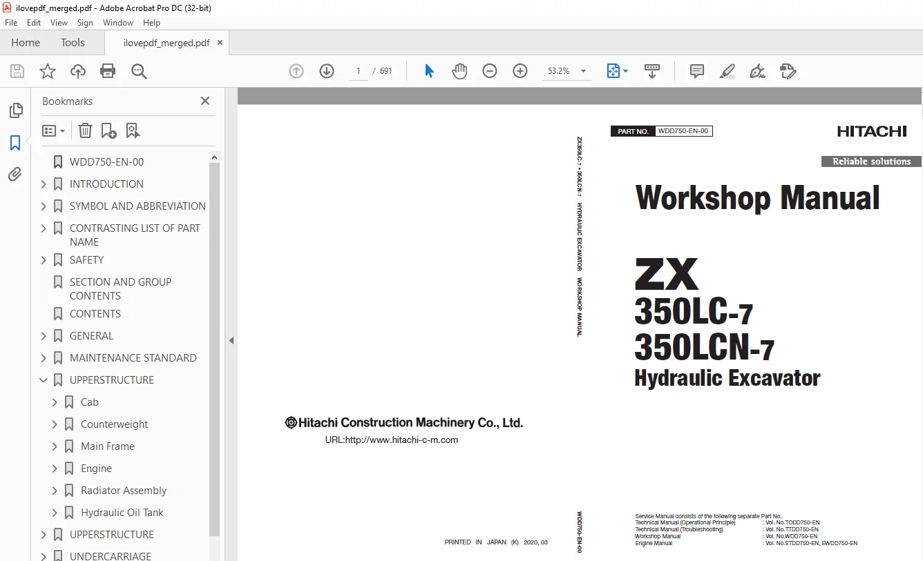
Service Manual consists of the following separate Part No.
Technical Manual (Operational Principle) : Vol. No.TODD750-EN
Technical Manual (Troubleshooting) : Vol. No.TTDD750-EN
Workshop Manual : Vol. No.WDD750-EN
Engine Manual : Vol. No.ETDD750-EN, EWDD750-EN
Description
Hitachi ZX 350LC-7 350LCN-7 Hydraulic Excavator WORKSHOP MANUAL PT WDD750-EN-00 – PDF DOWNLOAD
FILE DETAILS:
Hitachi ZX 350LC-7 350LCN-7 Hydraulic Excavator WORKSHOP MANUAL PT WDD750-EN-00 – PDF DOWNLOAD
Language :English
Pages :691
Downloadable : Yes
File Type : PDF
IMAGES PREVIEW OF THE MANUAL:
DESCRIPRION:
Hitachi ZX 350LC-7 350LCN-7 Hydraulic Excavator WORKSHOP MANUAL PT WDD750-EN-00 – PDF DOWNLOAD
Service Manual consists of the following separate Part No.
Technical Manual (Operational Principle) : Vol. No.TODD750-EN
Technical Manual (Troubleshooting) : Vol. No.TTDD750-EN
Workshop Manual : Vol. No.WDD750-EN
Engine Manual : Vol. No.ETDD750-EN, EWDD750-EN
This manual is written for an experienced technician to provide technical information needed to maintain and repair this machine.
The machine specification and description according to destination may be explained on this manual.
●Be sure to thoroughly read this manual for correct product information and service procedures.
●If you have any questions or comments, at if you found any errors regarding the contents of this manual, please contact using “Service Manual Revision Request Form” at the end of this manual. (Note: Do not tear off the form. Copy this form for usage.)
•Service Material Development Center Hitach Construction Machinery Co., Ltd.
•TEL: 81-29-832-9673
•FAX: 81-29-831-1162
•E-mail: [email protected]
All information, illustrations and specifications in this manual are based on the latest product information available at the time of publication. The right is reserved to make changes at any time without notice.
Additional References
Please refer to the other materials (operator’s manual, parts catalog, engine technical material and Hitachi training material etc.) in addition to this manual.
Manual Composition
This manual consists the Technical Manual, the Workshop Manual and the Engine Manual.
●Information included in the Technical Manual: Technical information needed for redelivery and delivery
•Operation and activation of all devices and systems, operational performance tests, and troubleshooting procedures.
●Information included in the Workshop Manual: Technical information needed for maintenance and repair of the machine
•Tools and devices needed for maintenance and repair, maintenance standards, and removal / installation and assemble / disassemble procedures
●Information included in the Engine Manual: Technical information needed for redelivery and delivery and maintenance and repair of the machine
•Operation and activation of all devices and systems, troubleshooting and assemble / disassemble procedures
TABLE OF CONTENTS:
Hitachi ZX 350LC-7 350LCN-7 Hydraulic Excavator WORKSHOP MANUAL PT WDD750-EN-00 – PDF DOWNLOAD
Service Manual consists of the following separate Part No.
Technical Manual (Operational Principle) : Vol. No.TODD750-EN
Technical Manual (Troubleshooting) : Vol. No.TTDD750-EN
Workshop Manual : Vol. No.WDD750-EN
Engine Manual : Vol. No.ETDD750-EN, EWDD750-EN
WDD750-EN-00 1
INTRODUCTION 3
To The Reader 3
Additional References 3
Manual Composition 3
Page Number 3
Trademark 4
Safety Alert Symbol and Headline Notations 4
Units Used 4
SYMBOL AND ABBREVIATION 7
Symbol and Abbreviation 7
CONTRASTING LIST OF PART NAME 9
Contrasting List of Part Name between Technical Manual and Parts Catalog 9
SAFETY 11
Recognize Safety Information 11
Understand Signal Words 11
Follow Safety Instructions 12
Prepare for Emergencies 13
Wear Protective Clothing 13
Protect Against Noise 14
Inspect Machine 14
General Precautions for the Cab 15
Use Handrail and Steps 15
Adjust the Operator’s Seat 16
Ensure Safety Before Rising from or Leaving Operator’s Seat 16
Fasten Your Seat Belt 16
Move and Operate Machine Safely 17
Start the Engine Only from Operator’s Seat 17
Jump Starting 18
Keep Riders off Machine 18
Precautions for Operations 19
Perform Job Site Risk Assessment Beforehand 20
Install OPG Guard 21
Restriction of Attachment Installation 21
Provide Signals for Jobs Involving Multiple Machines 21
Confirm Direction of Machine Travel 22
Drive Machine Safely 23
Avoid Injury from Rollaway Accidents 25
Avoid Accidents from Reversing and Swing Operation 26
Keep People Clear from Working Area 27
Never Position the Bucket Over Anyone 27
Avoid Undercutting 28
Avoid Tipping 28
Never Undercut a High Bank 29
Dig with Caution 29
Caution with an Overhead Obstacle 30
Avoid Power Lines 30
Precautions for Lightning 31
Object Handling 31
Protect Against Flying Debris and Falling Object 32
Park Machine Safely 33
Handle Fluids Safely−Avoid Fires 34
Transport Safely 35
Practice Maintenance Safely 36
Warn Others of Service Work 37
Support Machine Properly 38
Stay Clear of Moving Parts 38
Prevent Parts from Flying 39
Avoid Injury from Attachment Falling Accident 39
Prevent Burns 40
Replace Rubber Hoses Periodically 41
Avoid High-Pressure Fluids 41
Prevent Fires 42
Check for Oil Leaks: 42
Check for Short circuits: 42
Clean up Flammable Materials: 43
Check Key Switch: 43
Check Heat Shields: 43
Evacuating in Case of Fire 44
Beware of Exhaust Fumes 44
Precautions for Welding and Grinding 45
Avoid Heating Near Pressurized Fluid Lines 45
Avoid Applying Heat to Lines Containing Flammable Fluids 45
Precautions for Handling Accumulator and Gas Damper 46
Remove Paint Before Welding or Heating 46
Beware of Asbestos and Silica Dust and Other Contamination 46
Prevent Battery Explosions 47
Service Air Conditioning System Safely 47
Handle Chemical Products Safely 48
Dispose of Waste Properly 48
Never Ride Attachment 49
Notes on Aftertreatment Device 49
Precautions for Communication Terminal 49
Precautions for Communication Terminal Equipment 50
Notes on Protection by Operator’s Station when the Machine Rolls Over 51
Before Returning the Machine to the Customer 51
SECTION AND GROUP CONTENTS 53
CONTENTS 57
GENERAL 69
Precautions for Disassembling and Assembling 71
Precautions for Disassembling and Assembling 71
Precautions for Using Floating Seal 73
Precautions for Using Nylon Sling 75
Maintenance Standard Terminology 77
Tightening 79
Tightening Bolts and Nuts 79
Bolt Types 81
Specified Tightening Torque Chart 83
Tightening Order 85
Precautions for Spilt Flange 87
Nut and Bolt Locking 89
Tightening Piping Joint 91
Union Joint 93
Pipe Joint 95
O-Ring Face Seal Joint 97
Quick Coupling 99
Screw-In Connection101
Seal Tape Application103
Low-Pressure-Hose Clamp Tightening105
Connecting Hose107
Painting109
Painting109
Bleeding Air111
Bleeding Air from Hydraulic System111
Bleeding Air from Pump113
Bleeding Air from Travel Motor, Swing Motor115
Bleeding Air from Hydraulic Circuit117
Bleeding Air from Fuel System119
Air Bleeding from the Diesel Exhaust Fluid Defrosting Piping121
Preparation123
Preparation before Inspection and Maintenance123
Hydraulic Circuit Pressure Release Procedure125
Pressure Release from Hydraulic Oil Tank127
Pressure Release from Expansion Tank129
MAINTENANCE STANDARD131
Upperstructure133
Maintenance Standard for Pump Device133
Maintenance Standard for Swing Motor137
Undercarriage141
Maintenance Standard for Travel Motor141
Maintenance Standard for Sprocket143
Maintenance Standard of Front Idler145
Maintenance Standard for Upper Roller147
Maintenance Standard for Lower Roller149
Maintenance Standard of Track151
Front Attachment155
Maintenance Standard for Pin and Bushing155
Maintenance Standard for Side Cutter (2021232, 2021233)157
Maintenance Standard for Point (4512365)159
Maintenance Standard for Side Cutter (4435856, 4435857)161
Maintenance Standard for Point (4400253)163
Standard Dimensions for Arm and Bucket Connection165
Standard Dimensions for Arm and Boom Connection167
Maintenance Standard for Cylinder169
UPPERSTRUCTURE171
Cab175
Removal of Cab Interior Parts175
Removal of Cab Exterior Parts185
Removal of Cab Body189
Removal of Controller Assembly and Parts Around the Monitor193
Installation of Controller Assembly and Parts Around the Monitor199
Installation of Cab Body205
Installation of Cab Exterior Parts209
Installation of Cab Interior Parts213
Dimensions of Cab Glass223
Procedure to Remove Cab Glass233
Procedure to Install Cab Glass235
Procedures to Install Upper Door Glass243
Procedures to Install Upper Front Glass245
Counterweight247
Removal of Counterweight247
Installation of Counterweight249
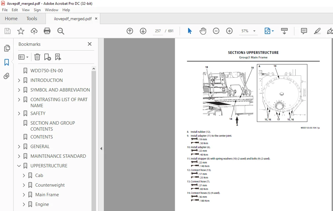
Main Frame251
Removal of Main Frame251
Installation of Main Frame255
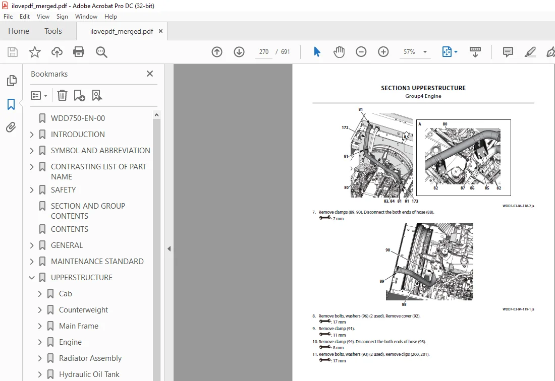
Engine261
Preparation before Removal of Engine261
Removal of Covers and Related Parts Around the Engine263
Removal of Wire Harnesses and Hoses Around the Engine269
Removal of Engine Body277
Installation of Engine Body279
Installation of Wire Harnesses and Hoses Around the Engine281
Installation of Related Parts of the Engine293
Work after Installation of Engine and Installation of Covers295
Radiator Assembly301
Removal of Radiator301
Installation of Radiator309
Removal of Intercooler315
Installation of Intercooler321
Removal of Oil Cooler327
Installation of Oil Cooler335
Hydraulic Oil Tank343
Removal of Hydraulic Oil Tank343
Installation of Hydraulic Oil Tank351
UPPERSTRUCTURE 0
Solenoid Valve359
Removal of Pilot Shut-Off Solenoid Valve359
Installation of Pilot Shut-Off Solenoid Valve361
Disassembly of Pilot Shut-Off Solenoid Valve363
Assembly of Pilot Shut-Off Solenoid Valve365
Removal of 5-Spool Solenoid Valve Unit367
Installation of 5-Spool Solenoid Valve Unit371
Structure of 5-Spool Solenoid Valve Unit375
Removal of 2-Spool Solenoid Valve Unit377
Installation of 2-Spool Solenoid Valve Unit379
Structure of 2-Spool Solenoid Valve Unit381
Removal of 3-Spool Solenoid Valve Unit383
Installation of 3-Spool Solenoid Valve Unit387
Structure of 3-Spool Solenoid Valve Unit389
Signal Control Valve391
Removal of Signal Control Valve391
Installation of Signal Control Valve395
Structure of Signal Control Valve397
Aftertreatment Device401
Removal of Aftertreatment Device401
Installation of Aftertreatment Device415
DEF Tank429
Removal of DEF Tank429
Installation of DEF Tank435
Removal of DEF Tank Suction Filter441
Installation of DEF Tank Suction Filter447
Removal of DEF Tank Water Supply Inlet Filter453
Installation of DEF Tank Water Supply Inlet Filter455
Assembly of DEF Tank Water Supply Inlet Filter457
Coolant Control Valve459
Removal of Coolant Control Valve459
Installation of Coolant Control Valve461
DEF Supply Module463
Removal of DEF Supply Module463
Installation of DEF Supply Module465
UNDERCARRIAGE467
Swing Bearing469
Removal of Swing Bearing469
Installation of Swing Bearing471
Disassembly of Swing Bearing475
Assembly of Swing Bearing479
Travel Device481
Removal of Travel Device481
Installation of Travel Device483
Disassembly of Travel Device485
Assembly of Travel Device491
Disassembly of Travel Motor499
Assembly of Travel Motor503
Disassembly of Brake Valve509
Assembly of Brake Valve511
Center Joint513
Removal of Center Joint513
Installation of Center Joint515
Disassembly of Center Joint517
Assembly of Center Joint519
Replacement of Body and Spindle523
Track Adjuster525
Removal of Track Adjuster525
Installation of Track Adjuster527
Disassembly of Front Idler529
Assembly of Front Idler533
Disassembly of Track Adjuster537
Assembly of Track Adjuster541
Upper and Lower Rollers545
Removal of Upper Roller545
Installation of Upper Roller547
Removal of Lower Roller551
Installation of Lower Roller555
Disassembly of Lower Roller559
Assembly of Lower Roller563
Track567
Removal of Track567
Installation of Track571
FRONT ATTACHMENT577
Front Attachment579
Removal of Front Attachment579
Installation of Front Attachment585
Removal of Bucket591
Installation of Bucket595
Removal of Arm599
Installation of Arm603
Cylinder607
Removal of Boom Cylinder607
Installation of Boom Cylinder611
Disassembly of Boom Cylinder617
Assembly of Boom Cylinder621
Removal of Arm Cylinder623
Installation of Arm Cylinder627
Disassembly of Arm Cylinder633
Assembly of Arm Cylinder637
Removal of Bucket Cylinder641
Installation of Bucket Cylinder645
Disassembly of Bucket Cylinder649
Assembly of Bucket Cylinder653
Removal of Positioning Cylinder655
Installation of Positioning Cylinder659
Disassembly of Positioning Cylinder665
Assembly of Positioning Cylinder669
Hose Rupture Valve671
Removal of Hose Rupture Valve for Boom Cylinder671
Installation of Hose Rupture Valve for Boom Cylinder673
Structure of Hose Rupture Valve for Boom Cylinder (Right)675
Structure of Hose Rupture Valve for Boom Cylinder (Left)677
Removal of Hose Rupture Valve for Arm Cylinder679
Installation of Hose Rupture Valve for Arm Cylinder681
Structure of Hose Rupture Valve for Arm Cylinder683
Removal of Hose Rupture Valve for Positioning Cylinder685
Installation of Hose Rupture Valve for Positioning Cylinder687
Structure of Hose Rupture Valve for Positioning Cylinder689
SERVICE MANUAL REVISION REQUEST FORM691
S.M 30/1/25