Hitachi ZX 890LCH-7 890LCR-7 Hydraulic Excavator Troubleshooting Technical Manual PN:TTJBR41
$31.95
Hitachi ZX 890LCH-7 890LCR-7 Hydraulic Excavator Troubleshooting Technical Manual PN:TTJBR41 – PDF DOWNLOAD
Service Manual consists of the following separate Part No.
Technical Manual (Operational Principle) : Vol. No.TOJBR41-EN
Technical Manual (Troubleshooting) : Vol. No.TTJBR41-EN
Workshop Manual : Vol. No.WJBR41-EN
Engine Manual : Vol. No.ETJAQ51-EN, EWJAQ51-EN
Description
Hitachi ZX 890LCH-7 890LCR-7 Hydraulic Excavator Troubleshooting Technical Manual PN:TTJBR41 – PDF DOWNLOAD
FILE DETAILS:
Hitachi ZX 890LCH-7 890LCR-7 Hydraulic Excavator Troubleshooting Technical Manual PN:TTJBR41 – PDF DOWNLOAD
Language :English
Pages :645
Downloadable : Yes
File Type : PDF
IMAGES PREVIEW OF THE MANUAL:
DESCRIPRION:
Hitachi ZX 890LCH-7 890LCR-7 Hydraulic Excavator Troubleshooting Technical Manual PN:TTJBR41 – PDF DOWNLOAD
Service Manual consists of the following separate Part No.
Technical Manual (Operational Principle) : Vol. No.TOJBR41-EN
Technical Manual (Troubleshooting) : Vol. No.TTJBR41-EN
Workshop Manual : Vol. No.WJBR41-EN
Engine Manual : Vol. No.ETJAQ51-EN, EWJAQ51-EN
INTRODUCTION
To The Reader
This manual is written for an experienced technician to provide technical information needed to maintain and repair this
machine.
The machine specification and description according to destination may be explained on this manual.
● Be sure to thoroughly read this manual for correct product information and service procedures.
● If you have any questions or comments, at if you found any errors regarding the contents of this manual, please
contact using “Service Manual Revision Request Form” at the end of this manual. (Note: Do not tear off the form. Copy
this form for usage.)
• Service Material Development Center Hitach Construction Machinery Co., Ltd.
• TEL: 81-29-832-9673
• FAX: 81-29-831-1162
• E-mail: [email protected]
All information, illustrations and specifications in this manual are based on the latest product information available at the
time of publication. The right is reserved to make changes at any time without notice.
Additional References
Please refer to the other materials (operator’s manual, parts catalog, engine technical material and Hitachi training
material etc.) in addition to this manual.
Manual Composition
This manual consists the Technical Manual, the Workshop Manual and the Engine Manual.
● Information included in the Technical Manual: Technical information needed for redelivery and delivery
• Operation and activation of all devices and systems, operational performance tests, and troubleshooting
procedures.
● Information included in the Workshop Manual: Technical information needed for maintenance and repair of the
machine
• Tools and devices needed for maintenance and repair, maintenance standards, and removal / installation and
assemble / disassemble procedures
● Information included in the Engine Manual: Technical information needed for redelivery and delivery and
maintenance and repair of the machine
• Operation and activation of all devices and systems, troubleshooting and assemble / disassemble procedures
TABLE OF CONTENTS:
Hitachi ZX 890LCH-7 890LCR-7 Hydraulic Excavator Troubleshooting Technical Manual PN:TTJBR41 – PDF DOWNLOAD
Service Manual consists of the following separate Part No.
Technical Manual (Operational Principle) : Vol. No.TOJBR41-EN
Technical Manual (Troubleshooting) : Vol. No.TTJBR41-EN
Workshop Manual : Vol. No.WJBR41-EN
Engine Manual : Vol. No.ETJAQ51-EN, EWJAQ51-EN
TTJBR41-EN-00 1
INTRODUCTION 3
To The Reader 3
Additional References 3
Manual Composition 3
Page Number 3
Trademark 4
Safety Alert Symbol and Headline Notations 4
Units Used 4
SYMBOL AND ABBREVIATION 7
Symbol and Abbreviation 7
CONTRASTING LIST OF PART NAME 9
Contrasting List of Part Name between Technical Manual and Parts Catalog 9
SAFETY 11
Recognize Safety Information 11
Understand Signal Words 11
Follow Safety Instructions 12
Prepare for Emergencies 13
Wear Protective Clothing 13
Protect Against Noise 14
Inspect Machine 14
General Precautions for the Cab 15
Use Handrail and Steps 15
Adjust the Operator’s Seat 16
Ensure Safety Before Rising from or Leaving Operator’s Seat 16
Fasten Your Seat Belt 16
Move and Operate Machine Safely 17
Start the Engine Only from Operator’s Seat 17
Jump Starting 18
Keep Riders off Machine 18
Precautions for Operations 19
Perform Job Site Risk Assessment Beforehand 20
Install OPG Guard 21
Restriction of Attachment Installation 21
Provide Signals for Jobs Involving Multiple Machines 21
Confirm Direction of Machine Travel 22
Drive Machine Safely 23
Avoid Injury from Rollaway Accidents 25
Avoid Accidents from Reversing and Swing Operation 26
Keep People Clear from Working Area 27
Never Position the Bucket Over Anyone 27
Avoid Undercutting 28
Avoid Tipping 28
Never Undercut a High Bank 29
Dig with Caution 29
Caution with an Overhead Obstacle 30
Avoid Power Lines 30
Precautions for Lightning 31
Lifting Application 31
Protect Against Flying Debris and Falling Object 32
Park Machine Safely 33
Handle Fluids Safely−Avoid Fires 34
Transport Safely 35
Practice Maintenance Safely 36
Warn Others of Service Work 37
Support Machine Properly 38
Stay Clear of Moving Parts 38
Prevent Parts from Flying 39
Avoid Injury from Attachment Falling Accident 39
Prevent Burns 40
Replace Rubber Hoses Periodically 41
Avoid High-Pressure Fluids 41
Prevent Fires 42
Check for Oil Leaks: 42
Check for Short circuits: 42
Clean up Flammable Materials: 43
Check Key Switch: 43
Check Heat Shields: 43
Evacuating in Case of Fire 44
Beware of Exhaust Fumes 44
Precautions for Welding and Grinding 45
Avoid Heating Near Pressurized Fluid Lines 45
Avoid Applying Heat to Lines Containing Flammable Fluids 45
Precautions for Handling Accumulator and Gas Damper 46
Remove Paint Before Welding or Heating 46
Beware of Asbestos and Silica Dust and Other Contamination 46
Prevent Battery Explosions 47
Service Air Conditioning System Safely 47
Handle Chemical Products Safely 48
Dispose of Waste Properly 48
Never Ride Attachment 49
Notes on Aftertreatment Device 49
Precautions for Communication Terminal 49
Precautions for Communication Terminal Equipment 50
Before Returning the Machine to the Customer 50
SECTION AND GROUP CONTENTS 53
CONTENTS 55
OPERATIONAL PERFORMANCE TEST 65
Introduction 67
Operational Performance Tests 67
Preparation for Performance Tests 68
Standard 71
Operational Performance Standard Table 71
Engine System Performance Standards 71
Travel System Performance Standards 72
Swing System Performance Standards 72
Front Attachment System Performance Standards 73
Lever System Performance Standards 73
Combined Operation System Performance Standards 74
Components System Performance Standards 74
Main Pump P-Q Diagram 75
Fan Pump I-Q Diagram 76
Engine Control Dial Activating Range 76
Pilot Pressure Sensor (4436535) Activating Range 77
Pump Displacement Control Pressure Sensor (4436536) Activating Range 77
Pump Delivery Pressure Sensor (4668254) Activating Range 78
Monitor Indicating Values of ECM 79
Monitor Indicating Values of MC 81
Monitor Indicating Values of MC (Pressure Sensor) 84
Monitor Indicating Values of MC (Solenoid Valve) 86
Monitor Indicating Values of Switch Box Controller 87
Engine Test 89
Engine Speed 89
Lubricant Consumption 91
Machine Performance Test 93
Travel Speed 93
Track Link Revolution Speed 93
Mistrack Check 94
Travel Parking Leakage 95
Swing Speed 96
Swing Function Drift Check 97
Swing Motor Leakage 99
Maximum Swingable Slant Angle100
Swing Bearing Play101
Hydraulic Cylinder Cycle Time103
Dig Function Drift Check (Maximum Reach Position)104
Dig Function Drift Check (Arm Roll-In Position)106
Control Lever Operating Force107
Control Lever Stroke108
Combined Operation of Boom Raise and Swing Function Check108
Combined Operation of Boom Raise and Arm Roll-In Function Check110
Component Test113
Primary Pilot Pressure113
Secondary Pilot Pressure114
4-Spool Solenoid Valve Unit Set Pressure (Control Valve Side)115
4-Spool Solenoid Valve Unit Set Pressure (Hydraulic Oil Tank Side)118
Main Pump Delivery Pressure120
Fan Pump Delivery Pressure121
Main Relief Set Pressure122
Main Relief Valve Pressure Adjustment Procedure124
High-Pressure Side of Main Relief Pressure Adjustment Procedure125
Low-Pressure Side of Main Relief Pressure Adjustment Procedure127
Relief Pressure (When Relieving Swing)128
Relief Pressure (When Relieving Travel)129
Overload Relief Valve Set Pressure130
Overload Relief Valve Pressure Adjustment Procedure (Reference)131
Main Pump Flow Rate132
Fan Pump Flow Rate134
Adjustment of Main Pump Flow Rate Control136
Adjustment of Fan Pump Flow Rate Control137
Swing Motor Drainage138
Travel Motor Drainage141
Radiator Fan Motor Drainage142
Oil Cooler Fan Motor Drainage144
Adjustment147
Rewrite of Aftertreatment Device Serial No147
How to Clear Fault Code147
Measuring Method of No-Load-Max Differential Pressure149
Differential Pressure Sensor Learning150
Filter Maintenance151
Procedure after Replacing DCU and ECM151
Air Bleeding from the Diesel Exhaust Fluid Defrosting Piping152
How to Check Manual Regeneration Switch154
Remedy at DEF Pressure Decrease155
Clean DEF Tank156
Remedy when Mixing Oil in DEF Tank160
Calibration of Aerial Angle160
Oil Monitoring Sensor Setting168
[A] Constant Change (Oil Monitoring Sensor Setting)169
[D] Sensor Collective Diagnosis (Oil Monitoring Sensor Functional Check)172
[B] Diagnosis of Engine Oil Monitoring Sensor (Oil Monitoring Sensor Functional Check)175
[C] Diagnosis of Hydraulic Oil Monitoring Sensor (Oil Monitoring Sensor Functional Check)178
TTJBR41-EN-00 0
TROUBLESHOOTING183
Diagnosing Procedure191
Introduction191
Diagnosis Procedure192
Electrical System Inspection195
Precautions for Inspection and Maintenance195
Instructions for Disconnecting Connectors197
Instructions for Removing Relays199
Fuse Inspection201
Fuse Connection Destination201
Fusible Link Inspection203
Battery Voltage Check206
Alternator Check206
Continuity Check208
Voltage and Current Measurement of 24-Volt Circuit209
Voltage and Current Measurement of 5-Volt Circuit214
Check by False Signal217
Test Wire Harness217
Removal of ECM219
Installation of ECM220
Removal of DCU221
Installation of DCU223
Removal of MC (Main Controller)225
Installation of MC (Main Controller)228
Removal of Monitor Controller231
Installation of Monitor Controller234
Removal of GSM238
Installation of GSM241
Removal of Aerial Angle Controller245
Installation of Aerial Angle Controller248
Mounting Position of Pump Delivery Pressure Sensor251
Mounting Position of Pump Displacement Control Pressure Sensor252
Mounting Position of Boom Raise Pilot Pressure Sensor253
Mounting Position of Boom Lower Pilot Pressure Sensor253
Mounting Position of Arm Roll-Out Pilot Pressure Sensor254
Mounting Position of Arm Roll-In Pilot Pressure Sensor255
Mounting Position of Bucket Roll-Out Pilot Pressure Sensor255
Mounting Position of Bucket Roll-In Pilot Pressure Sensor256
Mounting Position of Travel Pilot Pressure Sensor257
Mounting Position of 4-Spool and 5-Spool Pilot Pressure Sensor Pilot Pressure Sensor257
Mounting Position of Swing Pilot Pressure Sensor258
Mounting Position of Front Pilot Pressure Sensor259
Mounting Position of Attachment Pilot Pressure Sensor260
Mounting Position of Fuel Sensor261
Mounting Position of Hydraulic Oil Temperature Sensor261
Mounting Position of Differential Pressure Sensor262
Mounting Position of Exhaust Temperature Sensor263
Mounting Position of NOx Sensor264
Mounting Position of Engine Oil Monitoring Sensor265
Mounting Position of Hydraulic Oil Monitoring Sensor266
Mounting Position of Ambient Temperature Sensor266
Mounting Position of Re-circulated Air Temperature Sensor267
Mounting Position of Frost Sensor267
Mounting Position of Solar Radiation Sensor268
Monitor269
Basic Screen of Monitor269
Operating Procedures of Service Menu269
How to Display Service Menu270
How to Display Troubleshooting Screen272
How to Display Monitoring275
Monitoring Items of Engine Controller (ECM)279
Monitoring Items of Main Controller (MC)281
Monitoring Items of PLCU286
Monitoring Items of Monitor Controller (Information)286
Monitoring Items of Switch Box Controller287
Monitoring Items of Air Conditioner Unit288
How to Display Controller Version288
How to Display Operation289
How to Display Communication Terminal Status291
List of Communication Terminal Status292
Operating Procedures of Breaker Alarm293
Operating Procedures of Machine Setting (Constant Change)295
List of Machine Setting Items298
Operating Procedures of Monitor Setting (Operation Permission)299
Operating Procedures of Monitor Setting (Maintenance Items)302
List of Monitor Setting Items305
Operating Procedures of Attachment Setting (Constant Change)308
List of Attachment Setting Items310
Operating Procedures of Engine Setting313
How to Display Aftertreatment Device No315
Attachment Adjustment316
Operating Procedures of Pump Flow Rate317
Inspection of Engine Oil Level and Coolant Level320
Inspection of Hour Meter and Fuel Gauge321
Fuel Gauge322
Coolant Temperature Gauge323
DEF Gauge323
Hydraulic Oil Temperature Gauge324
e-Service325
Outline of e-Service325
List of Operation Data325
Communication System327
Component Layout329
Main Component (Upperstructure)329
Main Component (Undercarriage)331
Main Component (Front Attachment)331
Electrical System (Overview)332
Electrical System (Rear Tray)333
Electrical System (Switches)334
Electrical System (Utility Space)335
Electrical System (Around Battery)336
Engine Oil Monitoring Sensor337
Hydraulic Oil Monitoring Sensor338
Engine339
Aftertreatment Device340
Pump Device341
Control Valve342
Signal Control Valve342
Pilot Check Valve343
Swing Device344
Travel Device344
4-Spool Solenoid Valve Unit (Control Valve Side)344
4-Spool Solenoid Valve Unit (Hydraulic Oil Tank Side)345
Expansion Tank345
Air Cleaner346
DEF Tank346
DEF Supply Module347
Electric Fuel Pump347
Around Radiator348
Around Oil Cooler349
Shockless Valve349
Radiator Fan Valve350
Oil Cooler Fan Valve350
Boom Upper Area351
Arm Upper Area351
Distribution Valve (Upperstructure)352
Auto-Lubrication Device352
Components in Control Valve353
Pilot Valve Side of Pilot Port364
Control Valve Side of Pilot Port365
Port Layout of Control Valve (Main Circuit)367
Port Layout of Control Valve (Pilot Circuit)369
Cab Harness372
Main Harness380
Pump Harness389
NOx Harness390
Monitor Harness391
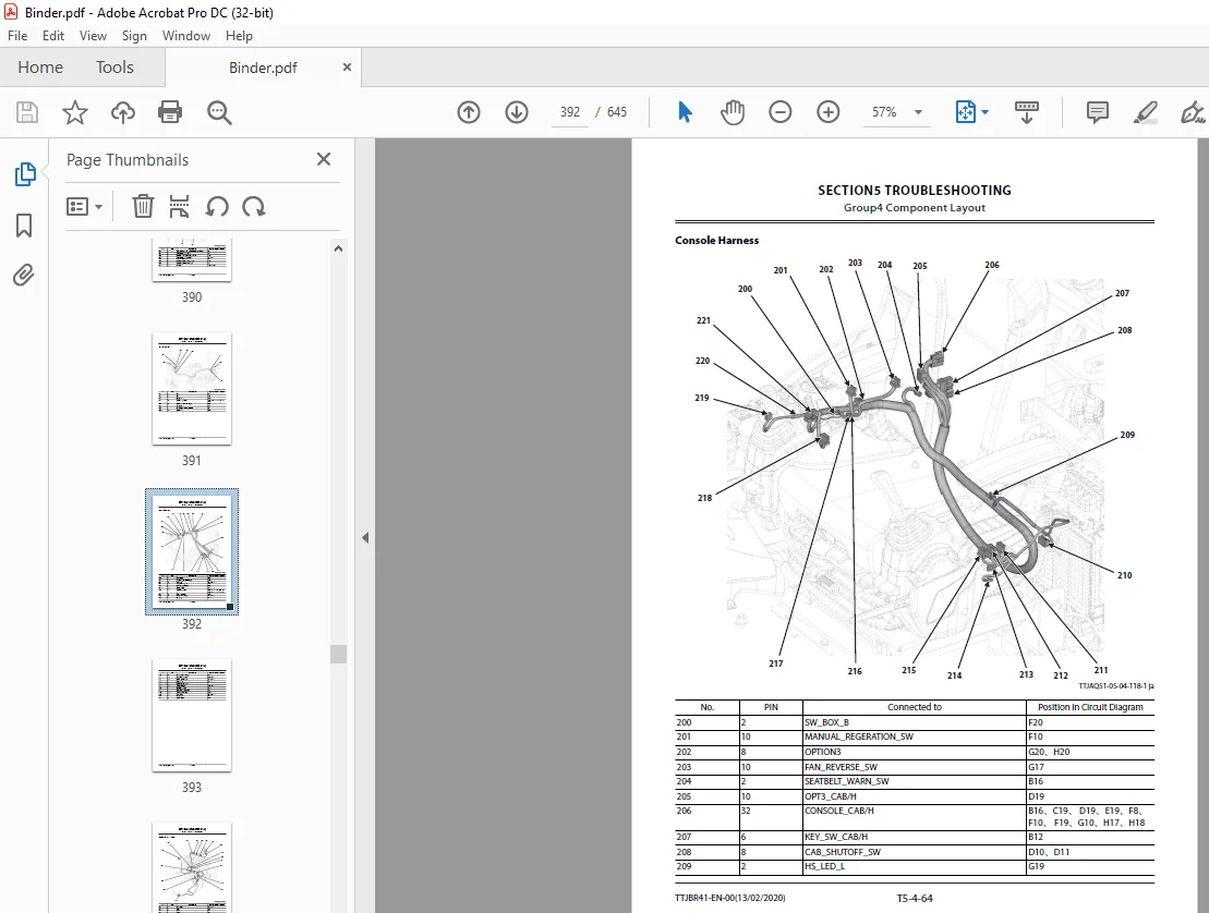
Console Harness392
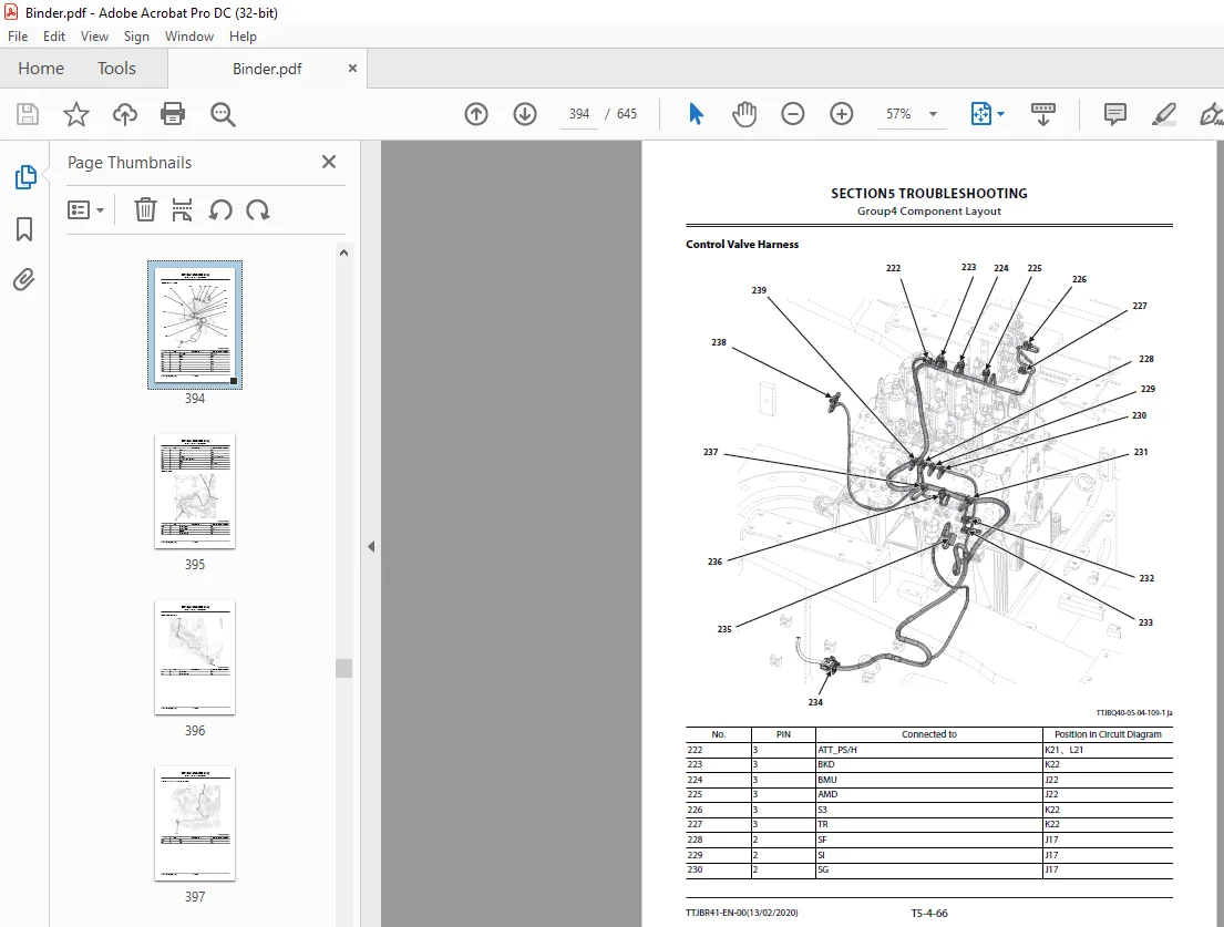
Control Valve Harness394
Wiper Harness395
Wiper Motor Harness396
Pilot Shut-Off Solenoid Valve Harness397
Engine Stop Switch Harness398
Cigar Lighter Sub Harness399
Engine Harness400
Rear View Camera Harness401
Oil Cooler Harness402
Auto Lubrication Harness403
Connector Layout of Monitor Controller404
Connector Layout of MC405
Connector Layout of ECM and VGS Controller406
Connector Layout of DCU407
Connector Layout of GSM 407
Connector Layout of Aerial Angle Controller408
Connector Layout of PLCU (Option)408
Troubleshooting A409
Troubleshooting A (Base Machine Diagnosis by Using Fault Codes) Procedure409
Contents of Troubleshooting A409
MC Fault Code 73000-3410
MC Fault Code 73000-4412
MC Fault Code 73001-3414
MC Fault Code 73001-4415
MC Fault Code 73002-3415
MC Fault Code 73003-2416
MC Fault Code 73004-2416
MC Fault Code 73005-2416
MC Fault Code 73006-2417
MC Fault Code 41000-2417
MC Fault Code 51000-3418
MC Fault Code 51000-4418
MC Fault Code 51001-3419
MC Fault Code 51001-4420
MC Fault Code 51046-3421
MC Fault Code 51046-4421
MC Fault Code 51045-3422
MC Fault Code 51045-4423
MC Fault Code 53000-3424
MC Fault Code 53000-4425
MC Fault Code 53001-3426
MC Fault Code 53001-4427
MC Fault Code 53022-3427
MC Fault Code 53022-4428
MCの故障コード53004-3429
MCの故障コード53004-4430
MC Fault Code 53005-3430
MC Fault Code 53005-4431
MC Fault Code 53006-3432
MC Fault Code 53006-4433
MC Fault Code 53015-3433
MC Fault Code 53015-4434
MC Fault Code 53016-3435
MC Fault Code 53016-4436
MC Fault Code 53029-3436
MC Fault Code 53029-4437
MC Fault Code 53023-3438
MC Fault Code 53023-4439
MC Fault Code 53024-3439
MC Fault Code 53024-4440
MC Fault Code 53025-3441
MC Fault Code 53025-4442
MC Fault Code 51041-2442
MC Fault Code 51041-6443
MC Fault Code 51041-5444
MC Fault Code 51042-2444
MC Fault Code 51042-6445
MC Fault Code 51042-5445
MC Fault Code 51009-2446
MC Fault Code 51009-6447
MC Fault Code 51009-5447
MC Fault Code 51040-2448
MC Fault Code 51040-6449
MC Fault Code 51040-5449
MC Fault Code 55000-2450
MC Fault Code 55000-6450
MC Fault Code 55000-5451
MC Fault Code 51038-2452
MC Fault Code 51038-6452
MC Fault Code 51038-5453
MC Fault Code 51043-2454
MC Fault Code 51043-6454
MC Fault Code 51043-5455
MC Fault Code 51051-2456
MC Fault Code 51051-6456
MC Fault Code 51051-5457
MC Fault Code 51052-2458
MC Fault Code 51052-6458
MC Fault Code 51052-5459
MC Fault Code 51037-2460
MC Fault Code 51037-6460
MC Fault Code 51037-5461
MC Fault Code 51050-2462
MC Fault Code 51050-6462
MC Fault Code 51050-5463
MC Fault Code 51044-2463
MC Fault Code 51044-6464
MC Fault Code 51044-5464
MC Fault Code 51039-2465
MC Fault Code 51039-6465
MC Fault Code 51039-5466
MC Fault Code 51021-3466
MC Fault Code 51021-4467
MC Fault Code 51022-3468
MC Fault Code 51022-4469
MC Fault Code 51025-0470
MC Fault Code 63000-2470
MC Fault Code 73007-2471
MC Fault Code 73034-2471
Monitor Controller (Information) Fault Code 41001-2471
Monitor Controller (Information) Fault Code 41002-3472
Monitor Controller (Information) Fault Code 41003-3472
Monitor Controller (Information) Fault Code 41003-4473
Monitor Controller (Information) Fault Code 73033-2475
Monitor Controller (Information) Fault Code 41004-14475
Monitor Controller (Information) Fault Code 41005-14475
Monitor Controller (Information) Fault Code 41006-14476
Monitor Controller (Information) Fault Code 41007-14476
Monitor Controller (Information) Fault Code 41008-14477
Monitor Controller (Information) Fault Code 41004-20477
Monitor Controller (Information) Fault Code 73013-2477
Monitor Controller (Information) Fault Code 73014-2478
Monitor Controller (Information) Fault Code 73015-2478
Monitor Controller (Information) Fault Code 73016-2479
Monitor Controller (Information) Fault Code 73017-2479
Monitor Controller (Information) Fault Code 73018-2479
Monitor Controller (Information) Fault Code 73019-2480
Monitor Controller (Information) Fault Code 73020-2480
Monitor Controller (Information) Fault Code 73021-2481
Monitor Controller (Information) Fault Code 68004-12481
Monitor Controller (Information) Fault Code 68005-12481
Monitor Controller (Information) Fault Code 68006-12482
Monitor Controller (Information) Fault Code 68007-12482
Monitor Controller (Information) Fault Code 68008-12482
Monitor Controller (Information) Fault Code 68009-12482
Monitor Controller (Information) Fault Code 41002-4482
Monitor Controller (Information) Fault Code 73029-2483
Monitor Controller (Monitor) Fault Code 73010-2483
Monitor Controller (Monitor) Fault Code 73011-2484
Monitor Controller (Monitor) Fault Code 73012-2484
Monitor Controller (Monitor) Fault Code 73030-2484
Monitor Controller (Monitor) Fault Code 13911-3485
Monitor Controller (Monitor) Fault Code 13912-4485
Monitor Controller (Monitor) Fault Code 13913-3486
Monitor Controller (Monitor) Fault Code 13914-4487
Monitor Controller (Monitor) Fault Code 13917-3487
Monitor Controller (Monitor) Fault Code 13918-4488
Monitor Controller (Monitor) Fault Code 13921-3488
Monitor Controller (Monitor) Fault Code 13922-4489
Monitor Controller (Monitor) Fault Code 13943-2489
Monitor Controller (Monitor) Fault Code 13944-2490
Monitor Controller (Monitor) Fault Code 13951-2491
Monitor Controller (Monitor) Fault Code 13991-2491
Monitor Controller (Monitor) Fault Code 13992-2492
Switch Box Controller Fault Code 14504-3492
Switch Box Controller Fault Code 14504-4492
Aerial Angle Controller Fault Code 68000-2493
Aerial Angle Controller Fault Code 68001-2493
Aerial Angle Controller Fault Code 68002-2494
Aerial Angle Controller Fault Code 73022-2495
Aerial Angle Controller Fault Code 68003-2495
Power-CAN harness Check495
Body-CAN Harness Check497
ISO-CAN (Engine) Harness Check499
IF-CAN Harness Check501
OPT-CAN Harness Check502
ECM Fault Code List502
DCU Fault Code List512
Troubleshooting B523
Troubleshooting B (Machine Diagnosis by Using Trouble Symptom) Procedure523
Contents of Troubleshooting B523
Relationship between Machine Trouble Symptoms and Related Parts525
When a Fault Occurs in MC (Main Controller)525
When a Fault Occurs in Switch Box Controller525
When a Fault Occurs in Engine Control Dial525
When a Fault Occurs in Auto-Idle Switch526
When a Fault Occurs in Power Mode Switch526
When a Fault Occurs in Travel Mode Switch526
When a Fault Occurs in Power Digging Switch527
When a Fault Occurs in Pilot Shut-Off Switch (Pilot Shut-Off Lever)527
When a Fault Occurs in Manual Regeneration Switch528
When a Fault Occurs in Aerial Angle Switch528
When a Fault Occurs in Learning Switch528
When a Fault Occurs in Fan Reverse Rotation Switch529
When a Fault Occurs in Boom Mode Selector Switch529
When a Fault Occurs in Auto-Lubrication Switch529
When a Fault Occurs in Proximity Switch530
When a Fault Occurs in Pilot Shut-Off Solenoid Valve530
When a Fault Occurs in Hydraulic Oil Temperature Sensor530
When a Fault Occurs in Differential Pressure Sensor531
When a Fault Occurs in DOC Inlet Exhaust Temperature Sensor531
When a Fault Occurs in DOC Outlet Exhaust Temperature Sensor531
When a Fault Occurs in SCR Exhaust Temperature Sensor532
When a Fault Occurs in Pump 1 Delivery Pressure Sensor532
When a Fault Occurs in Pump 2 Delivery Pressure Sensor532
When a Fault Occurs in Pump 1 Displacement Control Pressure Sensor533
When a Fault Occurs in Pump 2 Displacement Control Pressure Sensor533
When a Fault Occurs Swing Pilot Pressure Sensor533
When a Fault Occurs in Boom Raise Pilot Pressure Sensor534
When a Fault Occurs in Boom Lower Pilot Pressure Sensor534
When a Fault Occurs in Arm Roll-In Pilot Pressure Sensor534
When a Fault Occurs in Travel Pilot Pressure Sensor535
When a Fault Occurs in Front Pilot Pressure Sensor535
When a Fault Occurs in Bucket Roll-In Pilot Pressure Sensor536
When a Fault Occurs in Arm Roll-Out Pilot Pressure Sensor536
When a Fault Occurs in Bucket Roll-Out Pilot Pressure Sensor536
When a Fault Occurs in 5-Spool Pilot Pressure Sensor537
When a Fault Occurs in 4-Spool Pilot Pressure Sensor537
When a Fault Occurs in Attachment Pilot Pressure Sensor (Option)537
When a Fault Occurs in Pump 2 Control Solenoid Valve538
When a Fault Occurs in Pump 1 Control Solenoid Valve538
When a Fault Occurs in Swing Flow Rate Control Solenoid Valve (SI)538
When a Fault Occurs in Maximum Boom Mode Selector Control Solenoid Valve (SF)539
When a Fault Occurs in Travel Motor Displacement Angle Solenoid Valve (SC)539
When a Fault Occurs in Main Relief Valve Control Solenoid Valve (SF)540
When a Fault Occurs in Arm 2 Flow Rate Control Solenoid Valve (SG)540
When a Fault Occurs in Arm Regenerative Control Solenoid Valve (SI)541
When a Fault Occurs in 4-Spool Bypass Shut-Out Control Solenoid Valve (SG)541
When a Fault Occurs in 5-Spool Bypass Shut-Out Control Solenoid Valve (SC)542
When a Fault Occurs in Fan Reverse Rotation Control Solenoid Valve542
When a Fault Occurs in Fan Pump Control Solenoid Valve542
When a Fault Occurs in Main Relief Valve543
When a Fault Occurs in Overload Relief Valve543
When a Fault Occurs in Boom Anti-Drift Valve544
When a Fault Occurs in Arm Rod Anti-Drift Valve544
When a Fault Occurs in Flow Combiner Valve544
When a Fault Occurs in Boom Regenerative Valve545
When a Fault Occurs in Arm Regenerative Valve545
When a Fault Occurs in Arm Regeneration Cut Valve545
When a Fault Occurs in Bucket Regenerative Valve546
When a Fault Occurs in Bucket Regeneration Cut Valve546
When a Fault Occurs in Arm 1 Flow Rate Control Valve547
When a Fault Occurs in Arm 2 Flow Rate Control Valve547
When a Fault Occurs in Swing Flow Rate Control Valve548
When a Fault Occurs in Boom Flow Rate Control Valve548
When a Fault Occurs in Auxiliary Flow Combiner Valve549
When a Fault Occurs in Pump 1 Bypass Shut-Out Valve549
When a Fault Occurs in Pump 2 Bypass Shut-Out Valve550
When a Fault Occurs in Boom Lower Meter-In Cut Valve550
When a Fault Occurs in Travel Motor Displacement Angle Control Valve551
When a Fault Occurs in Swing Parking Brake Release Spool551
When a Fault Occurs in Arm Flow Rate Control Valve Control Spool551
When a Fault Occurs in Flow Combiner Valve Control Spool552
Identification Symbol of Troubleshooting B552
Correlation between Trouble Symptoms and Part Failures554
Parts Related with “E-1 Starter does not rotate”554
Parts Related with “E-2 Even if starter rotates, engine does not start”554
Parts Related with “E-3 Even if power mode switch is operated, power mode is not shifted”554
Parts Related with “E-4 ECO, PWR mode is faulty”555
Parts Related with “E-5 Even if travel lever is single operation with ECO or PWR mode, engine speed does not increase”555
Parts Related with “E-6 Auto-idle system is faulty”555
Parts Related with “E-9 Auto shut-down is not activated”556
Parts Related with “E-12 Engine speed does not decrease when audio mute/one-touch idle switch is pushed”556
Parts Related with “A-1 All actuators do not work”557
Parts Related with “A-2 All actuator speeds are slow”557
Parts Related with “A-3 Actuator does not stop even if control lever is set to neutral”557
Parts Related with “A-4 Auto or manual regeneration of aftertreatment device cannot be performed”558
Parts Related with “A-5 Travel (right) operation speed is slow when performing travel single operation Bucket single operation speed is slow (All problems occur at the same time)”558
Parts Related with “A-6 Travel (left) operation speed is slow when performing travel single operation Attachment single operation speed is slow (All problems occur at the same time)”558
Parts Related with “A-11 Fan does not rotate normally”559
Parts Related with A-12 Fan does not rotate in reverse when fan reverse rotation switch is pressed559
Parts Related with “F-1 All front attachment actuator powers are weak”559
Parts Related with “F-2 Front attachment drifts remarkably”560
Parts Related with “F-3 When boom raise or arm roll-out is operated, boom or arm starts to move after moving slightly down”560
Parts Related with “F-4 Even if power digging switch is pushed, power does not increase Boom raise power is weak when performing digging operation”560
Parts Related with “F-5 Boom, arm, or bucket single operation is not operated Boom, arm, or bucket single operation speed is slow”561
Parts Related with “F-6 Bucket roll-in speed is slow or power is weak when performing digging operation”561
Parts Related with “F-7 When performing combined operation, arm does not start to move smoothly Arm starts to move slightly slow when performing arm single operation These troubles often occur when temperature is low”561
Parts Related with “F-8 When performing combined operation, boom does not start to move smoothly Boom starts to move slightly slow when performing boom lower single operation”562
Parts Related with “F-9 Boom lower speed above ground is faster than other actuators when performing combined operation Machine cannot be raised off the ground”562
Parts Related with “F-10 Arm roll-in speed is slow when performing combined operation of arm roll-in and bucket roll-in”562
Parts Related with “F-11 Arm roll-in speed is fast when performing arm level crowding operation Arm power is weak when performing digging operation”563
Parts Related with “F-12 Boom raise speed is slow when performing combined operation of swing and boom raise Arm roll-out speed is slow when performing combined operation of swing and arm roll-out”563
Parts Related with “F-25 Machine is raised off the ground even when boom mode selector switch is pressed”563
Parts Related with “S-1 Swing speed is slow or is not operated”564
Parts Related with “S-2 When starting swing operation, swing speed is fast”564
Parts Related with “S-3 Swing speed is slow when performing combined operation of swing and arm roll-in”565
Parts Related with “T-1 Both of right and left travels are not operated or travel speed is slow”565
Parts Related with “T-2 One side travel is not operated or travel speed is slow Machine mistracks”565
Parts Related with “T-3 Machine mistracks when performing combined operation of travel and front attachment”565
Parts Related with “T-4 Fast travel can not be selected Travel mode does not change from slow speed mode to fast speed mode”566
Parts Related with “O-1 Work light does not light”566
Parts Related with “O-2 Cab light does not light”566
Parts Related with “O-3 Wiper is not operated”567
Parts Related with “O-4 Washer is not operated”567
Parts Related with “O-5 Boom light does not light”567
Parts Related with “O-6 Camera image does not change when aerial angle switch is pressed”567
Parts Related with “O-7 Auto-lubrication does not activate when auto-lubrication switch is turned ON”568
Parts Related with “O-8 Auto-lubrication does not stop when lubrication time is exceeded Auto-lubrication does not stop when auto-lubrication switch is turned OFF”568
Parts Related with “O-9 Auto-lubrication device stops, and auto-lubrication alarm is displayed”568
E-1 Starter does not rotate568
E-2 Even if starter rotates, engine does not start570
E-3 Even if power mode switch is operated, power mode is not shifted570
E-4 ECO, PWR mode is faulty571
E-5 Even if travel lever is single operation with ECO or PWR mode, engine speed does not increase571
E-6 Auto-idle system is faulty572
E-9 Auto shut-down is not activated572
E-12 Engine speed does not decrease when audio mute/one-touch idle switch is pushed573
A-1 All actuators do not work574
A-2 All actuator speeds are slow575
A-3 Actuator does not stop even if control lever is set to neutral576
A-4 Auto or manual regeneration of aftertreatment device cannot be performed576
A-5 Travel (right) operation speed is slow when performing travel single operation Bucket single operation speed is slow (All problems occur at the same time)577
A-6 Travel (left) operation speed is slow when performing travel single operation Attachment single operation speed is slow (All problems occur at the same time)578
A-11 Fan does not rotate normally578
A-12 Fan does not rotate in reverse when fan reverse switch is pressed578
F-1 All front attachment actuator powers are weak579
F-2 Front attachment drifts remarkably579
F-3 When boom raise or arm roll-out is operated, boom or arm starts to move after moving slightly down580
F-4 Even if power digging switch is pushed, power does not increase Boom raise power is weak when performing digging operation581
F-5 Boom, arm, or bucket single operation is not operated Boom, arm, or bucket single operation speed is slow581
F-6 Bucket roll-in speed is slow or power is weak when performing digging operation582
F-7 When performing combined operation, arm does not start to move smoothly Arm starts to move slightly slow when performing arm single operation These troubles often occur when temperature is low582
F-8 When performing combined operation, boom does not start to move smoothly Boom starts to move slightly slow when performing boom lower single operation583
F-9 Boom lower speed above ground is faster than other actuators when performing combined operation Machine cannot be raised off the ground583
F-10 Arm roll-in speed is slow when performing combined operation of arm roll-in and bucket roll-in584
F-11 Arm roll-in speed is fast when performing arm level crowding operation Arm power is weak when performing digging operation584
F-12 Boom raise speed is slow when performing combined operation of swing and boom raise Arm roll-out speed is slow when performing combined operation of swing and arm roll-out585
F-25 Machine is raised off ground even when boom mode selector switch is pressed585
S-1 Swing speed is slow or is not operated585
S-2 When starting swing operation, swing speed is fast586
S-3 Swing speed is slow when performing combined operation of swing and arm roll-in587
T-1 Both of right and left travels are not operated or travel speed is slow588
T-2 One side travel is not operated or travel speed is slow Machine mistracks588
T-3 Machine mistracks when performing combined operation of travel and front attachment589
T-4 Fast travel can not be selected Travel mode does not change from slow speed mode to fast speed mode590
O-1 Work light does not light590
O-2 Cab light does not light591
O-3 Wiper is not operated591
O-4 Washer is not operated592
O-5 Boom light does not light593
O-6 Camera image does not change when aerial angle switch is pressed593
O-7 Auto-lubrication does not activate when auto-lubrication switch is turned ON594
O-8 Auto-lubrication does not stop when lubrication time is exceeded Auto-lubrication does not stop when auto-lubrication switch is turned OFF595
O-9 Auto-lubrication device stops, and auto-lubrication alarm is displayed595
Exchange Inspection596
How to Lower Boom in Case of Emergency and When Engine Stops without Hose Rupture Valve599
Air Conditioner601
Outline of Air Conditioner601
Component Layout of Air Conditioner602
Functions of Main Electrical Parts604
Troubleshooting of Air Conditioner607
Monitor Controller (Monitor) Fault Code 13911-3608
Monitor Controller (Monitor) Fault Code 13912-4608
Monitor Controller (Monitor) Fault Code 13913-3609
Monitor Controller (Monitor) Fault Code 13914-4610
Monitor Controller (Monitor) Fault Code 13917-3610
Monitor Controller (Monitor) Fault Code 13918-4611
Monitor Controller (Monitor) Fault Code 13921-3611
Monitor Controller (Monitor) Fault Code 13922-4612
Monitor Controller (Monitor) Fault Code 13943-2612
Monitor Controller (Monitor) Fault Code 13944-2613
Monitor Controller (Monitor) Fault Code 13951-2614
Monitor Controller (Monitor) Fault Code 13991-2614
Monitor Controller (Monitor) Fault Code 13992-2615
Faulty Cooling (1)616
Faulty Cooling (2)617
Faulty Cooling (3)618
Faulty Cooling (4)620
Faulty Cooling (5)622
Faulty Heating (1)623
Faulty Heating (2)625
Others626
Blower motor does not operate628
Compressor clutch does not operate629
Cooling Circuit Check by Using Manifold Gauge630
Work after Replacing Components633
Refill compressor oil633
Necessity of Purging634
Procedures for Charging Air Conditioner with Refrigerant634
Warm-Up Operation640
Hose and Pipe Tightening Torque642
SERVICE MANUAL REVISION REQUEST FORM643
The Attached Diagram List644
S.M 1/2/25