Hitachi ZX135US-5B Hydraulic Excavator Technical Workshop Manual (WDAE-EN-00) – PDF Download
Original price was: $78.95.$26.95Current price is: $26.95.
- Hitachi ZX135US-5B Hydraulic Excavator Technical Workshop Manual
- Part No:WDAE-EN-00
Description
Hitachi ZX135US-5B Hydraulic Excavator Technical Workshop Manual (WDAE-EN-00)
File Details:
Hitachi ZX135US-5B Hydraulic Excavator Technical Workshop Manual (WDAE-EN-00)
- Manual Language:English
- Downloadable:Yes
- Pages: 599
- Size: 7.51 MB
- Format:PDF
HITACHI ZX135US-5B HYDRAULIC EXCAVATOR TECHNICAL WORKSHOP MANUAL (WDAE-EN-00) – PDF DOWNLOAD:
Image Preview:
Description:
Hitachi ZX135US-5B Hydraulic Excavator Technical Workshop Manual (WDAE-EN-00)
To The Reader
This manual is written for an experienced technician to provide technical information needed to maintain and repair this machine.
The machine specification and description according to destination may be explained on this manual.
Be sure to thoroughly read this manual for correct product information and service procedures.
If you have any questions or comments, at if you found any errors regarding the contents of this manual, please contact using “Service Manual Revision Request Form” at the end of this manual.
Additional References
Please refer to the other materials (operator’s manual, parts catalog, engine technical material and Hitachi training material etc.) in addition to this manual.
Manual Composition
This manual consists the Technical Manual, the Workshop Manual and the Engine Manual.
Information included in the Technical Manual: Technical information needed for redelivery and delivery, operation and activation of all devices and systems, operational performance tests, and troubleshooting procedures.
Information included in the Workshop Manual: Technical information needed for maintenance and repair of the machine, tools and devices needed for maintenance and repair, maintenance standards, and removal / installation and assemble / disassemble procedures.
Information included in the Engine Manual: Technical information needed for redelivery and delivery and maintenance and repair of the machine, operation and activation of all devices and systems, troubleshooting and assemble / disassemble procedures.
Table Of Contents:
Hitachi ZX135US-5B Hydraulic Excavator Technical Workshop Manual (WDAE-EN-00)
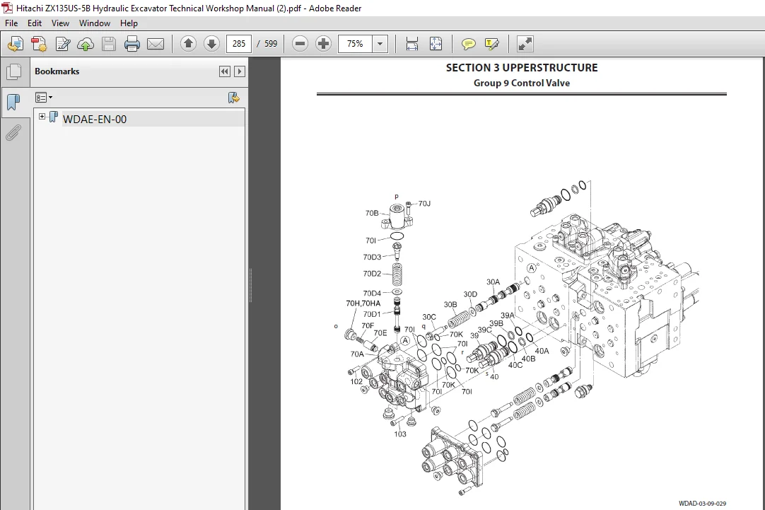
WDAE-EN-00......................................................................  1
	INTRODUCTION................................................................  3
		To The Reader...........................................................  3
		Additional References...................................................  3
		Manual Composition......................................................  3
		Page Number.............................................................  3
		Safety Alert Symbol and Headline Notations..............................  4
		Units Used..............................................................  4
	SYMBOL AND ABBREVIATION.....................................................  5
	SAFETY......................................................................  7
		Recognize Safety Information............................................  7
		Understand Signal Words.................................................  7
		Follow Safety Instructions..............................................  8
		Prepare for Emergencies.................................................  9
		Wear Protective Clothing................................................  9
		Protect Against Noise................................................... 10
		Inspect Machine......................................................... 10
		General Precautions for Cab............................................. 11
		Use Handholds and Steps................................................. 12
		Adjust the Operator's Seat.............................................. 12
		Ensure Safety Before Rising from or Leaving Operator’s Seat............. 13
		Fasten Your Seat Belt................................................... 13
		Move and Operate Machine Safely......................................... 14
		Operate Only from Operator's Seat....................................... 14
		Jump Starting........................................................... 15
		Keep Riders off Machine................................................. 15
		Precautions for Operations.............................................. 16
		Investigate Job Site Beforehand......................................... 17
		Install OPG Guard....................................................... 18
		Provide Signals for Jobs Involving Multiple Machines.................... 19
		Confirm Direction of Machine to Be Driven............................... 19
		Drive Machine Safely.................................................... 20
		Avoid Injury from Rollaway Accidents.................................... 22
		Avoid Injury from Back-Over and Swing Accidents......................... 23
		Keep Person Clear from Working Area..................................... 24
		Never Position Bucket Over Anyone....................................... 24
		Avoid Undercutting...................................................... 25
		Avoid Tipping........................................................... 25
		Never Undercut a High Bank.............................................. 26
		Dig with Caution........................................................ 26
		Operate with Caution.................................................... 26
		Avoid Power Lines....................................................... 27
		Precautions for Lightning............................................... 27
		Object Handling......................................................... 28
		Protect Against Flying Debris........................................... 28
		Park Machine Safely..................................................... 29
		Handle Fluids Safely−Avoid Fires........................................ 29
		Transport Safely........................................................ 30
		Practice Safe Maintenance............................................... 31
		Warn Others of Service Work............................................. 32
		Support Machine Properly................................................ 32
		Stay Clear of Moving Parts.............................................. 33
		Prevent Parts from Flying............................................... 33
		Store Attachments Safely................................................ 34
		Prevent Burns........................................................... 34
		Replace Rubber Hoses Periodically....................................... 35
		Avoid High-Pressure Fluids.............................................. 35
		Prevent Fires........................................................... 36
		Evacuating in Case of Fire.............................................. 38
		Beware of Exhaust Fumes................................................. 38
		Precautions for Welding and Grinding.................................... 39
		Avoid Heating Near Pressurized Fluid Lines.............................. 40
		Avoid Applying Heat to Lines Containing Flammable Fluids................ 40
		Precautions for Handling Accumulator and Gas Dumper..................... 40
		Remove Paint Before Welding or Heating.................................. 41
		Beware of Asbestos and Silicon Dust and Other Contamination............. 41
		Prevent Battery Explosions.............................................. 42
		Service Air Conditioning System Safely.................................. 42
		Handle Chemical Products Safely......................................... 43
		Dispose of Waste Properly............................................... 43
		Never Ride Attachment................................................... 44
		Notes for Muffler Filter................................................ 44
		Precautions for Communication Terminal.................................. 44
		Precaution for Communication Terminal Equipment......................... 45
		Before Returning the Machine to the Customer............................ 46
	SECTION AND GROUP CONTENTS.................................................. 47
	SECTION 1 GENERAL........................................................... 49
		Group 1 Precautions for Disassembling and Assembling.................... 51
			Precautions for Disassembling and Assembling........................ 51
		Group 2 Tightening...................................................... 57
			Tightening Bolts and Nuts........................................... 57
			Piping Joint........................................................ 60
		Group 3 Painting........................................................ 67
			Painting............................................................ 67
		Group 4 Bleeding Air.................................................... 69
			Bleeding Air from Hydraulic Oil Tank................................ 69
			Bleeding Air from Hydraulic System.................................. 70
			Bleeding Air from Fuel System....................................... 71
			Bleeding Air from Radiator.......................................... 73
		Group 5 Pressure Release Procedure...................................... 75
			Hydraulic Circuit Pressure Release Procedure........................ 75
		Group 6 Preparation..................................................... 77
			Preparation before Inspection and Maintenance....................... 77
	SECTION 2 MAINTENANCE STANDARD.............................................. 81
		Group 1 Upperstructure.................................................. 83
			Pump Device......................................................... 83
			Swing Motor......................................................... 85
			Swing Parking Brake................................................. 87
		Group 2 Undercarriage................................................... 89
			Travel Motor........................................................ 89
			Parking Brake....................................................... 91
			Sprocket............................................................ 92
			Front Idler......................................................... 93
			Upper Roller........................................................ 95
			Lower Roller........................................................ 96
			Track............................................................... 97
		Group 3 Front Attachment................................................101
			Pin and Bushing.....................................................101
			Side Cutter (2015428, 2015429)......................................103
			Point (Z963228).....................................................104
			Standard Dimensions for Arm and Bucket Connection...................105
			Standard Dimensions for Arm and Boom Connection.....................106
			Cylinder............................................................107
	SECTION 3 UPPERSTRUCTURE....................................................111
		Group 1 Cab.............................................................113
			Removal and Installation of Cab.....................................113
			Dimensions of Cab Glass.............................................139
		Group 2 Counterweight...................................................159
			Removal and Installation of Counterweight...........................159
		Group 3 Main Frame......................................................161
			Removal and Installation of Main Frame..............................161
		Group 4 Engine..........................................................175
			Removal and Installation of Engine..................................175
		Group 8 Pump Device.....................................................199
			Removal and Installation of Pump Device.............................199
			Removal and Installation of Coupling................................215
			Disassembly of Pump Device..........................................217
			Assembly of Pump Device.............................................224
			Disassembly of Regulator............................................233
			Assembly of Regulator...............................................235
			Disassembly of Solenoid Valve.......................................237
			Assembly of Solenoid Valve..........................................239
			Structure of Pilot Pump.............................................241
		Group 9 Control Valve...................................................243
			Removal and Installation of Control Valve...........................243
			Disassembly of Housing..............................................263
			Assembly of Housing.................................................265
			Disassembly of Control Valve (Housing A Side).......................267
			Assembly of Control Valve (Housing A Side)..........................275
			Disassembly of Control Valve (Housing B Side).......................283
			Assembly of Control Valve (Housing B Side)..........................294
			Removal and Installation of Blade Control Valve (Optional)..........305
			Disassembly of Blade Control Valve (Optional).......................309
			Assembly of Blade Control Valve (Optional)..........................311
		Group 10 Swing Device...................................................313
			Removal and Installation of Swing Device............................313
			Disassembly of Swing Device.........................................319
			Assembly of Swing Device............................................324
			Disassembly of Swing Motor..........................................331
			Assembly of Swing Motor.............................................334
			Disassembly of Valve Unit...........................................341
			Assembly of Valve Unit..............................................343
		Group 11 Pilot Valve....................................................345
			Removal and Installation of Pilot Valve (Left)......................345
			Removal and Installation of Pilot Valve (Right).....................351
			Removal and Installation of Travel Pilot Valve......................359
			Removal and Installation of Blade Pilot Valve.......................363
			Disassembly of Pilot Valves (Right and Left)........................371
			Assembly of Pilot Valves (Right and Left)...........................374
			Disassembly of Travel Pilot Valve...................................377
			Assembly of Travel Pilot Valve......................................381
			Disassembly of Blade Pilot Valve....................................387
			Assembly of Blade Pilot Valve.......................................390
		Group 12 Solenoid Valve.................................................393
			Removal and Installation of Pilot Shut-Off Solenoid Valve...........393
			Removal and Installation of 4-Spool Solenoid Valve Unit.............397
			Removal and Installation of 2-Spool Solenoid Valve Unit.............405
			Disassembly of Pilot Shut-Off Solenoid Valve........................409
			Assembly of Pilot Shut-Off Solenoid Valve...........................411
			Structure of 4-Spool Solenoid Valve Unit............................413
			Structure of 2-Spool Solenoid Valve Unit............................415
		Group 13 Signal Control Valve...........................................417
			Removal and Installation of Signal Control Valve....................417
			Structure of Signal Control Valve...................................425
		Group 14 Muffler Filter.................................................427
			Removal and Installation of Muffler Filter..........................427
			Disassembly of Muffler Filter.......................................435
			Assembly of Muffler Filter..........................................437
	SECTION 4 UNDERCARRIAGE.....................................................441
		Group 1 Swing Bearing...................................................443
			Removal and Installation of Swing Bearing...........................443
			Disassembly of Swing Bearing........................................449
			Assembly of Swing Bearing...........................................452
		Group 2 Travel Device...................................................455
			Removal and Installation of Travel Device...........................455
			Disassembly of Travel Device........................................457
			Assembly of Travel Device...........................................461
			Disassembly of Travel Motor.........................................467
			Assembly of Travel Motor............................................471
			Disassembly of Brake Valve..........................................477
			Assembly of Brake Valve.............................................479
			Precautions for Using Floating Seal.................................481
		Group 3 Center Joint....................................................483
			Removal and Installation of Center Joint (Without Blade)............483
			Removal and Installation of Center Joint (With Blade)...............487
			Disassembly of Center Joint (Without Blade).........................491
			Assembly of Center Joint (Without Blade)............................493
			Replacement of Body (Without Blade).................................496
			Disassembly of Center Joint (With Blade)............................497
			Assembly of Center Joint (With Blade)...............................499
			Replacement of Body (With Blade)....................................502
		Group 4 Track Adjuster..................................................503
			Removal and Installation of Track Adjuster..........................503
			Disassembly of Track Adjuster.......................................505
			Assembly of Track Adjuster..........................................510
		Group 5 Front Idler.....................................................513
			Removal and Installation of Front Idler.............................513
			Disassembly of Front Idler..........................................515
			Assembly of Front Idler.............................................518
			Precautions for Using Floating Seal.................................521
		Group 6 Upper and Lower Rollers.........................................523
			Removal and Installation of Upper Roller............................523
			Removal and Installation of Lower Roller............................527
			Disassembly of Lower Roller.........................................531
			Assembly of Lower Roller............................................533
			Precautions for Using Floating Seal.................................535
		Group 7 Track...........................................................537
			Removal and Installation of Track...................................537
		Group 8 Blade Cylinder..................................................543
			Removal and Installation of Blade Cylinder..........................543
			Disassembly of Blade Cylinder.......................................547
			Assembly of Blade Cylinder..........................................549
	SECTION 5 FRONT ATTACHMENT..................................................553
		Group 1 Front Attachment................................................555
			Removal and Installation of Front Attachment........................555
		Group 2 Cylinder........................................................561
			Removal and Installation of Boom Cylinder...........................561
			Removal and Installation of Arm Cylinder............................565
			Removal and Installation of Bucket Cylinder.........................571
			Disassembly of Boom, Arm, and Bucket Cylinders......................575
			Assembly of Boom, Arm, and Bucket Cylinders.........................582
		Group 3 Hose Rupture Valve..............................................587
			Removal and Installation of Hose Rupture Valve for Boom Cylinder....587
			Removal and Installation of Hose Rupture Valve for Arm Cylinder.....589
			Structure of Hose Rupture Valve for Boom Cylinder (Right)...........591
			Structure of Hose Rupture Valve for Boom Cylinder (Left)............593
			Structure of Hose Rupture Valve for Arm Cylinder....................595
	SERVICE MANUAL REVISION REQUEST FORM........................................599
Please Note:
⦁ This is not a physical manual but a digital manual – meaning no physical copy will be couriered to you. The manual can be yours in the next 2 mins as once you make the payment, you will be directed to the download page IMMEDIATELY.
⦁ This is the same manual used by the dealers inorder to diagnose your vehicle of its faults.
⦁ Require some other service manual or have any queries: please WRITE to us at [email protected]