Hitachi ZX135US-6 Hydraulic Excavator Operational Principle+Troubleshooting+Workshop Manual – PDF DOWNLOAD
$33.95
Hitachi ZX135US-6 Hydraulic Excavator Operational Principle+Troubleshooting+Workshop Manual
This Listing includes all of the manuals mentioned below:
Hitachi ZX135US-6 Hydraulic Excavator Electrical Circuit Diagram
Hitachi ZX135US-6 Hydraulic Excavator Hydraulic Circuit Diagram
Hitachi ZX135US-6 Hydraulic Excavator Technical Operational Principle Manual
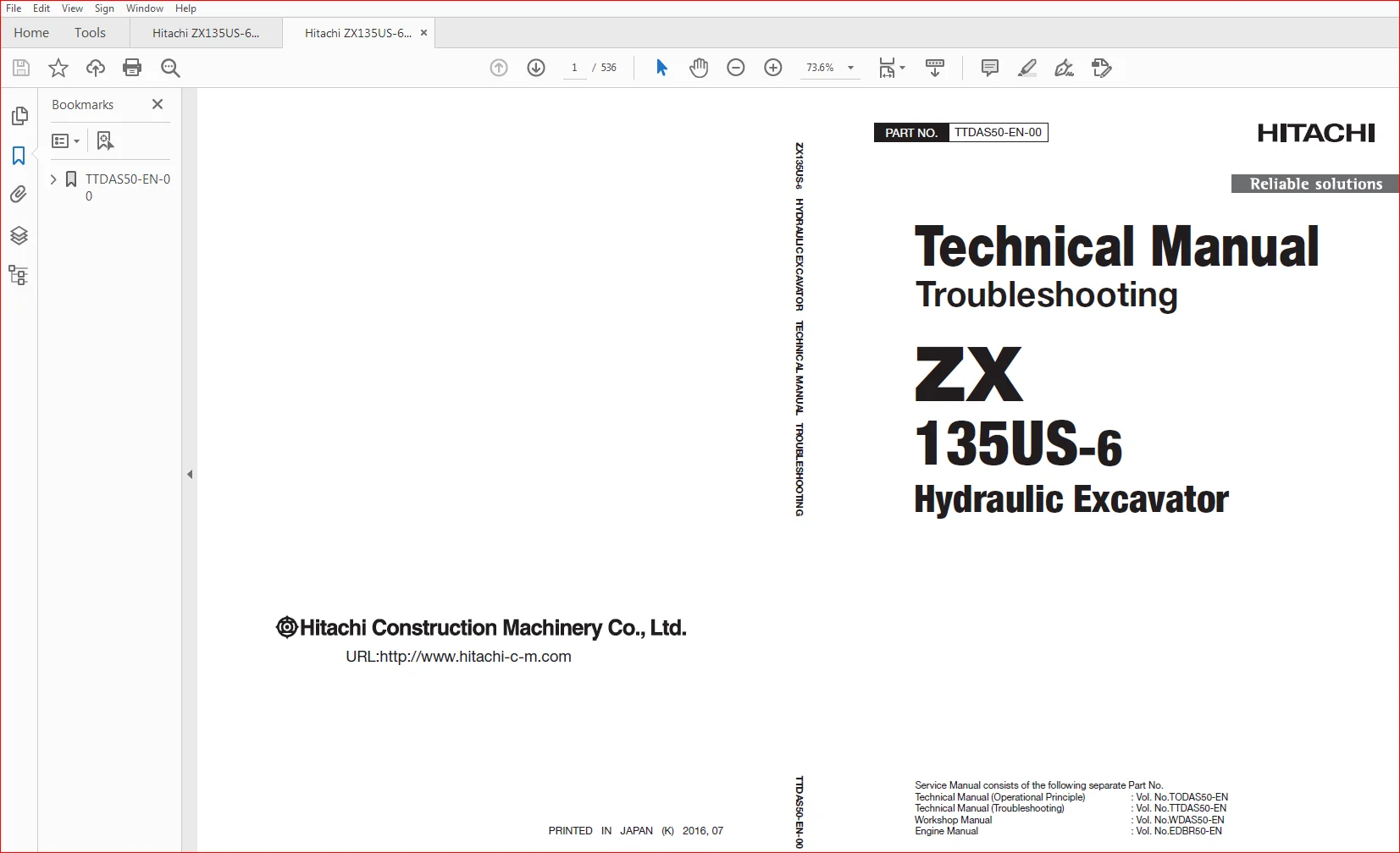
Hitachi ZX135US-6 Hydraulic Excavator Technical Troubleshooting Manual
Hitachi ZX135US-6 Hydraulic Excavator workshop Manual
Description
Hitachi ZX135US-6 Hydraulic Excavator Operational Principle+Troubleshooting+Workshop Manual
FILE DETAILS:
Hitachi ZX135US-6 Hydraulic Excavator Operational Principle+Troubleshooting+Workshop Manual
This Listing includes all of the manuals mentioned below:
Hitachi ZX135US-6 Hydraulic Excavator Electrical Circuit Diagram
Hitachi ZX135US-6 Hydraulic Excavator Hydraulic Circuit Diagram
Hitachi ZX135US-6 Hydraulic Excavator Technical Operational Principle Manual
Hitachi ZX135US-6 Hydraulic Excavator Technical Troubleshooting Manual
Hitachi ZX135US-6 Hydraulic Excavator workshop Manual
DESCRIPTION:
Hitachi ZX135US-6 Hydraulic Excavator Operational Principle+Troubleshooting+Workshop Manual
INTRODUCTION:
TO THE READER:
• This manual is written for an experienced technician to provide technical information needed to maintain and repair this machine.
• Be sure to thoroughly read this manual for correct product information and service procedures.
• If you have any questions or comments, at if you found any errors regarding the contents of this manual, please contact using “Service Manual Revision Request Form” at the end of this manual.
ADDITIONAL REFERENCES:
• Please refer to the materials listed below in addition to this manual.
• The Operator’s Manual
• The Parts Catalog
• The Engine Manual
• Parts Catalog of the Engine
• Hitachi Training Material
MANUAL COMPOSITION:
• This manual consists of three portions: the Technical Manual (Operational Principle), the Technical Manual (Troubleshooting) and the Workshop Manual.
• Information included in the Technical Manual (Operational Principle): technical information needed for redelivery and delivery, operation and activation of all devices and systems.
• Information included in the Technical Manual (Troubleshooting): technical information needed for operational performance tests, and troubleshooting procedures.
• Information included in the Workshop Manual: technical information needed for maintenance and repair of the machine, tools and devices needed for maintenance and repair, maintenance standards, and removal/installation and assemble/ disassemble procedures.
TABLE OF CONTENTS:
Hitachi ZX135US-6 Hydraulic Excavator Operational Principle+Troubleshooting+Workshop Manual
- Hitachi ZX135US-6 Hydraulic Excavator workshop Manual
SECTION 1
GENERAL
Group 1 Precautions for Disassembling and Assembling
Precautions for Disassembling and
AssemblingW1-1-1-1
Group 2 Tightening
Tightening Bolts and NutsW1-2-1-1
Piping JointW1-2-1-4
Group 3 Painting
PaintingW1-3-1-1
Group 4 Bleeding Air
Bleeding Air from Hydraulic SystemW1-4-1-1
Bleeding Air from Fuel SystemW1-4-1-2
Air Bleeding from the DEF Defrosting PipingW1-4-1-4
Group 5 Preparation
Preparation before Inspection and
MaintenanceW1-5-1-1
Hydraulic Circuit Pressure Release ProcedureW1-5-1-3
Pressure Release from Hydraulic Oil TankW1-5-1-4
Pressure Release from Expansion Tank W1-5-1-5
SECTION 2
MAINTENANCE STANDARD
Group 1 Upperstructure
Pump DeviceW2-1-1-1
Swing MotorW2-1-2-1
Swing Parking BrakeW2-1-2-3
Group 2 Undercarriage
Travel MotorW2-2-1-1
Parking BrakeW2-2-1-3
SprocketW2-2-1-4
Front IdlerW2-2-2-1
Upper RollerW2-2-3-1
Lower RollerW2-2-3-2
TrackW2-2-4-1
Group 3 Front Attachment
Pin and BushingW2-3-1-1
Side Cutter (2015428, 2015429)W2-3-1-3
Point (963228)W2-3-1-4
SECTION 3
UPPERSTRUCTURE
Standard Dimensions for Arm and Bucket
ConnectionW2-3-1-5
Standard Dimensions for Arm and Boom
ConnectionW2-3-1-6
CylinderW2-3-2-1
Group 1 Cab
Removal and Installation of CabW3-1-1-1
Dimensions of Cab GlassW3-1-2-1
Group 2 Counterweight
Removal and Installation of CounterweightW3-2-1-1
Group 3 Main Frame
Removal and Installation of Main FrameW3-3-1-1
Group 4 Engine
Removal and Installation of EngineW3-4-1-1
Group 8 Pump Device
Removal and Installation of Pump DeviceW3-8-1-1
Removal and Installation of CouplingW3-8-2-1
Disassembly of Pump DeviceW3-8-3-1
Assembly of Pump DeviceW3-8-3-8
Disassembly of RegulatorW3-8-4-1
Assembly of RegulatorW3-8-4-3
Disassembly of Solenoid Valve UnitW3-8-5-1
Assembly of Solenoid Valve UnitW3-8-5-3
Structure of Pilot Pump and Blade PumpW3-8-6-1
Group 9 Control Valve
Removal and Installation of Control ValveW3-9-1-1
Removal and Installation of Blade Control
ValveW3-9-2-1
Disassembly of HousingW3-9-3-1
Assembly of HousingW3-9-3-3
Disassembly of A-Side Control ValveW3-9-4-1
Assembly of A-Side Control ValveW3-9-4-9
Disassembly of B-Side Control ValveW3-9-5-1
Assembly of B-Side Control ValveW3-9-5-12
Disassembly of Blade Control ValveW3-9-6-1
Assembly of Blade Control ValveW3-9-6-3
Group 10 Swing Device
Removal and Installation of Swing DeviceW3-10-1-1
Disassembly of Swing Reduction GearW3-10-2-1
Assembly of Swing Reduction GearW3-10-2-6
Disassembly of Swing MotorW3-10-3-1
Assembly of Swing MotorW3-10-3-4
Disassembly of Valve UnitW3-10-4-1
Assembly of Valve UnitW3-10-4-3
Group 11 Pilot Valve
Removal and Installation of Pilot Valve (Left)W3-11-1-1
Removal and Installation of Pilot Valve
(Right)W3-11-2-1
Removal and Installation of Travel Pilot
ValveW3-11-3-1
Removal and Installation of Blade Pilot ValveW3-11-4-1
Disassembly of Pilot Valves (Right and Left)W3-11-5-1
Assembly of Pilot Valves (Right and Left)W3-11-5-4
Disassembly of Travel Pilot ValveW3-11-6-1
Assembly of Travel Pilot ValveW3-11-6-5
Disassembly of Blade and Positioning Pilot
ValvesW3-11-7-1
Assembly of Blade and Positioning Pilot
ValvesW3-11-7-4
Group 12 Solenoid Valve
Removal and Installation of Pilot Shut-Off
Solenoid ValveW3-12-1-1
Removal and Installation of 4-Spool Solenoid
Valve UnitW3-12-2-1
Removal and Installation of 2-Spool Solenoid
Valve UnitW3-12-3-1
Removal and Installation of Maximum Pump
1 Flow Rate Limit Control Solenoid ValveW3-12-4-1
Disassembly of Pilot Shut-Off Solenoid
ValveW3-12-5-1
Assembly of Pilot Shut-Off Solenoid ValveW3-12-5-3
Structure of 4-Spool Solenoid Valve UnitW3-12-6-1
Structure of 2-Spool Solenoid Valve UnitW3-12-7-1
Structure of Maximum Pump 1 Flow Rate
Limit Control Solenoid ValveW3-12-8-1
Group 13 Signal Control Valve
Removal and Installation of Signal Control
ValveW3-13-1-1
Structure of Signal Control ValveW3-13-2-1
Group 14 Aftertreatment Device
Removal and Installation of Aftertreatment
DeviceW3-14-1-1
Group 15 DEF Tank
Removal and Installation of DEF TankW3-15-1-1
Group 16 Coolant Control Valve
Removal and Installation of Coolant Control
ValveW3-16-1-1
Group 17 DEF Supply Module
Removal and Installation of DEF
Supply ModuleW3-17-1-1
SECTION 4
UNDERCARRIAGE
Group 1 Swing Bearing
Removal and Installation of Swing BearingW4-1-1-1
Disassembly of Swing BearingW4-1-2-1
Assembly of Swing BearingW4-1-2-4
Group 2 Travel Device
Removal and Installation of Travel DeviceW4-2-1-1
Disassembly of Travel DeviceW4-2-2-1
Assembly of Travel DeviceW4-2-2-5
Disassembly of Travel MotorW4-2-3-1
Assembly of Travel MotorW4-2-3-5
Disassembly of Brake ValveW4-2-4-1
Assembly of Brake ValveW4-2-4-3
Precautions for Using Floating SealW4-2-5-1
Group 3 Center Joint
Removal and Installation of Center Joint
(Without Blade)W4-3-1-1
Removal and Installation of Center Joint
(With Blade)W4-3-2-1
Disassembly of Center Joint (without Blade)W4-3-3-1
Assembly of Center Joint (without Blade)W4-3-3-3
Replacement of Body and SpindleW4-3-3-6
Disassembly of Center Joint (with Blade)W4-3-4-1
Assembly of Center Joint (with Blade)W4-3-4-3
Replacement of Body and SpindleW4-3-4-6
Group 4 Track Adjuster
Removal and Installation of Track AdjusterW4-4-1-1
Disassembly of Track AdjusterW4-4-2-1
Assembly of Track AdjusterW4-4-2-6
Precautions for Using Floating SealW4-4-3-1
Group 5 Front Idler
Removal and Installation of Front IdlerW4-5-1-1
Disassembly of Front IdlerW4-5-2-1
Assembly of Front IdlerW4-5-2-4
Precautions for Using Floating SealW4-5-3-1
Group 6 Upper and Lower Rollers
Removal and Installation of Upper RollerW4-6-1-1
Removal and Installation of Lower RollerW4-6-2-1
Disassembly of Lower RollerW4-6-3-1
Assembly of Lower RollerW4-6-3-3
Precautions for Using Floating SealW4-6-4-1
Group 7 Track
Removal and Installation of TrackW4-7-1-1
Group 8 Blade Cylinder
Removal and Installation of Blade CylinderW4-8-1-1
Disassembly of Blade CylinderW4-8-2-1
Assembly of Blade CylinderW4-8-2-4
SECTION 5
FRONT ATTACHMENT
Group 1 Front Attachment
Removal and Installation of Front AttachmentW5-1-1-1
Group 2 Cylinder
Removal and Installation of Boom CylinderW5-2-1-1
Removal and Installation of Arm CylinderW5-2-2-1
Removal and Installation of Bucket CylinderW5-2-3-1
Removal and Installation of Positioning
CylinderW5-2-4-1
Disassembly of Boom, Arm and Bucket
CylindersW5-2-5-1
Assembly of Boom, Arm and Bucket CylindersW5-2-5-7
Disassembly of Positioning CylinderW5-2-6-1
Assembly of Positioning CylinderW5-2-6-6
Group 3 Hose Rupture Valve
Removal and Installation of Hose Rupture
Valve for Boom CylinderW5-3-1-1
Removal and Installation of Hose Rupture
Valve for Arm CylinderW5-3-2-1
Removal and Installation of Hose Rupture
Valve for Positioning CylinderW5-3-3-1
Structure of Hose Rupture Valve for Boom
Cylinder (Right)W5-3-4-1
Structure of Hose Rupture Valve for Boom
Cylinder (Left)W5-3-4-3
Structure of Hose Rupture Valve for Arm
CylinderW5-3-4-5
Structure of Hose Rupture Valve for Positioning
CylinderW5-3-4-7
- Hitachi ZX135US-6 Hydraulic Excavator Technical Troubleshooting Manual
SECTION 4
OPERATIONAL PERFORMANCE TEST
Group 1 Introduction
Operational Performance TestsT4-1-1
Preparation for Performance TestsT4-1-2
Group 2 Standard
Operational Performance Standard TableT4-2-1
Main Pump P-Q Diagram (P1, P2)T4-2-11
Sensor Activating RangeT4-2-13
Monitor Indicating ValuesT4-2-14
Group 3 Engine Test
Engine SpeedT4-3-1
Lubricant ConsumptionT4-3-4
Group 4 Machine Performance Test
Travel SpeedT4-4-1
Track Revolution SpeedT4-4-2
Mistrack CheckT4-4-3
Travel Parking LeakageT4-4-4
Swing SpeedT4-4-5
Swing Function Drift CheckT4-4-6
Swing Motor LeakageT4-4-8
Maximum Swingable Slant AngleT4-4-10
Swing Bearing PlayT4-4-12
Hydraulic Cylinder Cycle TimeT4-4-14
Dig Function Drift CheckT4-4-16
Control Lever Operating ForceT4-4-20
Control Lever StrokeT4-4-21
Combined Operation of Boom Raise and Swing
Function CheckT4-4-22
Combined Operation of Boom Raise and Arm
Roll-In Function CheckT4-4-23
Clearance of Front Attachment Connecting
PartT4-4-24
Group 5 Component Test
Primary Pilot PressureT4-5-1
Secondary Pilot PressureT4-5-3
4-Spool Solenoid Valve Set PressureT4-5-4
2-Spool Solenoid Valve (Aftertreatment Device Regeneration Control) Set PressureT4-5-5
Main Pump Delivery PressureT4-5-7
Main Relief Set PressureT4-5-8
Relief Pressure (when relieving swing)T4-5-14
Overload Relief Valve Set PressureT4-5-16
Main Pump Flow Rate MeasurementT4-5-20
Swing Motor DrainageT4-5-28
Travel Motor DrainageT4-5-30
Group 6 Adjustment
Rewrite of Aftertreatment Device Serial NoT4-6-1
How to Clear Fault CodeT4-6-2
Procedure after Replacing DCU and ECMT4-6-3
Air Bleeding from the Diesel Exhaust Fluid
Defrosting PipingT4-6-4
How to Check Manual Regeneration SwitchT4-6-6
Remedy at DEF Pressure DecreaseT4-6-8
Remedy at DEF Abnormal QualityT4-6-10
Clean DEF TankT4-6-12
Remedy when Mixing Oil in DEF TankT4-6-14
SECTION 5
TROUBLESHOOTING
Group 1 Diagnosing Procedure
IntroductionT5-1-1
Diagnosis ProcedureT5-1-2
Electrical System InspectionT5-1-5
Precautions for Inspection and Maintenance T5-1-6
Instructions for Disconnecting ConnectorsT5-1-8
Fuse InspectionT5-1-10
Fusible Link InspectionT5-1-13
Battery Voltage CheckT5-1-14
Alternator CheckT5-1-15
Continuity CheckT5-1-16
Voltage and Current MeasurementT5-1-18
Check by False SignalT5-1-26
Test Wire HarnessT5-1-27
Group 2 Monitor
OutlineT5-2-1
Operating Procedures of Service MenuT5-2-2
Setting MenuT5-2-43
Inspection of Engine Oil Level, Coolant Level,
Hour Meter, and Fuel GaugeT5-2-48
Fuel Gauge, Coolant Temperature Gauge, DEF
GaugeT5-2-49
Group 3 e-Service
OutlineT5-3-1
List of Operation DataT5-3-2
Communication SystemT5-3-4
Group 4 Component Layout
Main ComponentT5-4-1
Electrical System (Overview)T5-4-5
Electrical System (Rear Tray)T5-4-6
Electrical System (Switch Panel)T5-4-7
Electrical System (Around Air Cleaner)T5-4-8
Electrical System (Relays)T5-4-9
EngineT5-4-10
Aftertreatment DeviceT5-4-11
Aftertreatment DeviceT5-4-12
Pump DeviceT5-4-13
Around Pump DeviceT5-4-14
Control ValveT5-4-15
Signal Control ValveT5-4-15
Swing DeviceT5-4-17
Travel DeviceT5-4-17
4-Spool Solenoid Valve UnitT5-4-18
Maximum Pump 1 Flow Rate Limit Control
Solenoid ValveT5-4-18
2-Spool Solenoid Valve Unit (Aftertreatment
Device Regeneration Control)T5-4-18
DEF TankT5-4-19
DEF Supply ModuleT5-4-19
Layout of Attachment Spec PartsT5-4-21
Components in Control ValveT5-4-26
Pilot PortT5-4-44
Group 5 Troubleshooting A
Troubleshooting A (Base Machine Diagnosis By
Using Fault Codes) ProcedureT5-5-1
MC Fault Code ListT5-5-3
ECM Fault Code ListT5-5-24
DCU Fault Code ListT5-5-38
Monitor Controller (Monitor) Fault Code ListT5-5-46
Monitor Controller (Information) Fault Code
ListT5-5-47
Air Conditioner Controller Fault Code ListT5-5-50
Communication Terminal Fault Code ListT5-5-51
MC Fault Codes 11000 to 11002T5-5-53
MC Fault Code 11003T5-5-54
MC Fault Codes 11006, 11007,11009T5-5-57
Monitor Controller (Monitor) Fault Codes 13002,
13003, 13005T5-5-57
CAN0 Harness CheckT5-5-58
ISO-CAN (Engine) Harness CheckT5-5-62
MC Fault Codes 11008, 11010T5-5-65
Monitor Controller (Monitor) Fault Codes 13004,
13006, 13007T5-5-65
CAN1 Harness CheckT5-5-66
MC Fault Code 11100T5-5-69
MC Fault Code 11101T5-5-70
MC Fault Codes 11200 to 11202T5-5-71
MC Fault Codes 11206 to 11208T5-5-72
MC Fault Codes 11301 to 11303T5-5-73
MC Fault Codes 11304, 11307, 11325T5-5-74
MC Fault Codes 11995, 11997T5-5-75
MC Fault Code 11400T5-5-76
MC Fault Code 11401T5-5-77
MC Fault Code 11402T5-5-78
MC Fault Code 11403T5-5-79
MC Fault Code 11407T5-5-80
MC Fault Code 11408T5-5-81
MC Fault Code 11409T5-5-82
MC Fault Code 11410T5-5-83
MC Fault Code 11428T5-5-84
MC Fault Codes 11434, 11435T5-5-85
MC Fault Code 11436T5-5-86
MC Fault Codes 11458, 11459T5-5-87
MC Fault Code 11901T5-5-88
MC Fault Codes 20010 to 20012T5-5-89
Monitor Controller (Information) Fault Codes
13304, 13310T5-5-90
Monitor Controller (Information) Fault Code
13311T5-5-91
Monitor Controller (Information) Fault Codes
20100 to 20114T5-5-92
Monitor Controller (Information) Fault Codes
20109 to 20149T5-5-93
Air Conditioner Controller Fault Codes 11 to 22T5-5-94
Air Conditioner Controller Fault Codes 43 to 92T5-5-95
Group 6 Troubleshooting B
Troubleshooting B (Machine Diagnosis by Using
Trouble Symptom) ProcedureT5-6-1
Relationship between Machine Trouble
Symptoms and Related PartsT5-6-3
Correlation between Trouble Symptoms and
Part FailuresT5-6-30
Engine System TroubleshootingT5-6-47
All Actuator System TroubleshootingT5-6-57
Front Attachment System TroubleshootingT5-6-66
Swing System TroubleshootingT5-6-80
Travel System TroubleshootingT5-6-82
Blade System Troubleshooting (Option)T5-6-88
Other System TroubleshootingT5-6-90
Exchange InspectionT5-6-95
How to Lowering Boom When Emergency and
When Engine Stops without Hose Rupture
ValveT5-6-98
How to Lowering Boom When Emergency and
When Engine Stops with Hose Rupture ValveT5-6-99
Attachment Circuit Pressure Release
ProcedureT5-6-100
Group 7 Air Conditioner
OutlineT5-7-1
Functions of Main PartsT5-7-4
TroubleshootingT5-7-9
Air Conditioner Controller Fault Code ListT5-7-10
Air Conditioner Controller Fault Codes 11 to 22T5-7-11
Air Conditioner Controller Fault Codes 43 to 92T5-7-12
Work after Replacing ComponentsT5-7-34
Refill Compressor OilT5-7-35
Charge Air Conditioner with RefrigerantT5-7-36
Hose and Pipe Tightening TorqueT5-7-44
- Hitachi ZX135US-6 Hydraulic Excavator Technical Operational Principle Manual
SECTION 1
GENERAL
Group 1 Specifications
SpecificationsT1-1-1
Working Ranges (Grouser shoe)T1-1-4
Group 2 Component Layout
Main ComponentT1-2-1
Electrical System (Overview)T1-2-5
Electrical System (Rear Tray)T1-2-6
Electrical System (Switch Panel)T1-2-7
Electrical System (Around Air Cleaner)T1-2-8
Electrical System (Relays)T1-2-9
EngineT1-2-10
Aftertreatment DeviceT1-2-11
Aftertreatment DeviceT1-2-12
Pump DeviceT1-2-13
Around Pump DeviceT1-2-14
Control ValveT1-2-15
Signal Control ValveT1-2-15
Swing DeviceT1-2-17
Travel DeviceT1-2-17
4-Spool Solenoid Valve UnitT1-2-18
Maximum Pump 1 Flow Rate Limit Control
Solenoid ValveT1-2-18
2-Spool Solenoid Valve Unit (Aftertreatment
Device Regeneration Control)T1-2-18
DEF TankT1-2-19
DEF Supply ModuleT1-2-19
Layout of Attachment Spec PartsT1-2-21
Group 3 Component Specifications
EngineT1-3-1
Engine AccessoriesT1-3-5
Hydraulic ComponentT1-3-6
Electrical ComponentT1-3-10
Optional PartsT1-3-11
SECTION 2
SYSTEM
Group 1 Controller
Outline T2-1-1
CAN Circuit T2-1-2
Group 2 Control System
Outline T2-2-1
Engine Control T2-2-4
Pump ControlT2-2-34
Valve Control (Standard)T2-2-52
Valve Control (Option)T2-2-70
Other ControlT2-2-80
Group 3 Engine System
ECM System T2-3-1
Fuel Injection Control T2-3-2
Fuel Injection Amount Correction ControlT2-3-10
EGR ControlT2-3-12
Preheating ControlT2-3-14
Variable Turbocharger ControlT2-3-15
Alarm ControlT2-3-16
Urea SCR SystemT2-3-17
Engine Output Restriction Control
(INDUCEMENT)T2-3-28
Aftertreatment DeviceT2-3-32
Aftertreatment Device Regeneration ControlT2-3-36
Group 4 Hydraulic System
Outline T2-4-1
Pilot Circuit T2-4-2
Main CircuitT2-4-14
Blade/Breaker/Pulverizer/Crusher Circuit
(Option)T2-4-32
Outline (2-Piece Boom)T2-4-41
Pilot Circuit (2-Piece Boom)T2-4-42
Main Circuit (2-Piece Boom)T2-4-46
Group 5 Electrical System
Outline T2-5-1
Main Circuit T2-5-2
Electric Power Circuit (Key Switch: OFF) T2-5-4
CAN Circuit T2-5-6
Accessory Related Circuit (Key Switch: ACC) T2-5-8
Starting Circuit (Key Switch: START) T2-5-10
Charging Circuit (Key Switch: ON)T2-5-12
Surge Voltage Prevention CircuitT2-5-16
Pilot Shut-Off Circuit (Key Switch: ON)T2-5-18
Auto Shut-Down Circuit/Automatic Engine Stop
Circuit at Low TemperatureT2-5-20
Engine Stop CircuitT2-5-22
Monitor CircuitT2-5-25
Security CircuitT2-5-26
Radio CircuitT2-5-28
Air Conditioner CircuitT2-5-28
Accessory CircuitT2-5-31
Work Light CircuitT2-5-32
Wiper/Washer CircuitT2-5-34
Cab Light CircuitT2-5-36
SECTION 3
COMPONENT OPERATION
Group 1 Pump Device
OutlineT3-1-1
Main PumpT3-1-2
RegulatorT3-1-4
Solenoid ValveT3-1-22
Pilot Pump, Blade Pump (Option)T3-1-24
Pump Delivery Pressure SensorT3-1-24
Pump Control Pressure SensorT3-1-24
Group 2 Swing Device
OutlineT3-2-1
Swing Reduction GearT3-2-2
Swing MotorT3-2-3
Swing Parking BrakeT3-2-4
Valve UnitT3-2-6
Group 3 Control Valve
OutlineT3-3-1
Hydraulic CircuitT3-3-20
Flow Combiner ValveT3-3-26
Main Relief ValveT3-3-28
Overload Relief Valve (with Make-Up Function)T3-3-32
Regenerative ValveT3-3-36
Anti-Drift ValveT3-3-44
Flow Rate Control ValveT3-3-48
Digging Regenerative ValveT3-3-52
Boom Lower Meter-In Cut ValveT3-3-54
Auxiliary Flow Combiner Valve and Bypass
Shut-Out ValveT3-3-56
Blade Control Valve (Option), Positioning
Control Valve (Option)T3-3-60
2-Piece Boom (Option)T3-3-62
Blade Circuit (Option)T3-3-66
Group 4 Pilot Valve
OutlineT3-4-1
Operation (Front Attachment/Swing and Travel
Pilot Valves)T3-4-3
Operation (Auxiliary, Blade, Positioning Pilot
Valves)T3-4-11
Shockless Function (Only for Travel Pilot Valve)T3-4-16
Group 5 Travel Device
OutlineT3-5-1
Travel Reduction GearT3-5-2
Travel MotorT3-5-4
Parking BrakeT3-5-6
Travel Brake ValveT3-5-8
Overload Relief ValveT3-5-12
Travel Mode ControlT3-5-14
Group 6 Signal Control Valve
OutlineT3-6-1
Pilot PortT3-6-2
Shuttle ValveT3-6-7
Shockless ValveT3-6-10
Pump 1 Flow Rate Control Valve, Pump 2 Flow
Rate Control ValveT3-6-14
Bucket Flow Rate Control Valve Control Spool,
Flow Combiner Valve Control Spool,
Swing Parking Brake Release Spool,
Arm 1 Flow Rate Control Valve Control SpoolT3-6-16
Group 7 Others (Upperstructure)
Pilot Shut-Off Solenoid ValveT3-7-1
Solenoid ValveT3-7-3
Hose Rupture ValveT3-7-8
Pilot Relief ValveT3-7-14
Recirculation Valve (Option)T3-7-15
Group 8 Others (Undercarriage)
Swing BearingT3-8-1
CenterjointT3-8-2
Track AdjusterT3-8-4
HITACHI ZX135US-6 HYDRAULIC EXCAVATOR OPERATIONAL PRINCIPLE+TROUBLESHOOTING+WORKSHOP MANUAL – PDF DOWNLOAD:
IMAGES PREVIEW OF THE MANUAL:
PLEASE NOTE:
- This is the SAME exact manual used by your dealers to fix your vehicle.
- The same can be yours in the next 2-3 mins as you will be directed to the download page immediately after paying for the manual.
- Any queries / doubts regarding your purchase, please feel free to contact [email protected]