Hitachi ZX210LCN-G Hydraulic Excavator Operational Principle Technical Manual – PDF Download
Original price was: $71.95.$25.95Current price is: $25.95.
- Hitachi ZX210LCN-G Hydraulic Excavator Operational Principle Technical Manual
- Part No:TODC390-EN-00
Description
Hitachi ZX210LCN-G Hydraulic Excavator Operational Principle Technical Manual
File Details:
Hitachi ZX210LCN-G Hydraulic Excavator Operational Principle Technical Manual
- Manual Language:English
- Pages: 238
- Size: 6.24 MB
- Downloadable:Yes
- Format:PDF
HITACHI ZX210LCN-G HYDRAULIC EXCAVATOR OPERATIONAL PRINCIPLE TECHNICAL MANUAL – PDF DOWNLOAD:
Image Preview:
Description:
Hitachi ZX210LCN-G Hydraulic Excavator Operational Principle Technical Manual
TO THE READER
This manual is written for an experienced technician to provide technical information needed to maintain and repair this machine. The machine specification and description according to destination may be explained on this manual.
• Be sure to thoroughly read this manual for correct product information and service procedures.
• If you have any questions or comments, at if you found any errors regarding the contents of this manual, please contact using “Service Manual Revision Request Form” at the end of this manual.
ADDITIONAL REFERENCES
Please refer to the other materials (operator’s manual, parts catalog, engine technical material and Hitachi training material etc.) in addition to this manual.
MANUAL COMPOSITION
This manual consists the Technical Manual and the Workshop Manual.
• Information included in the Technical Manual: technical information needed for redelivery and delivery, operation and activation of all devices and systems, operational performance tests, and troubleshooting procedures.
• Information included in the Workshop Manual: technical information needed for maintenance and repair of the machine, tools and devices needed for maintenance and repair, maintenance standards, and removal/installation and assemble/ disassemble procedures.
Table Of Contents:
Hitachi ZX210LCN-G Hydraulic Excavator Operational Principle Technical Manual
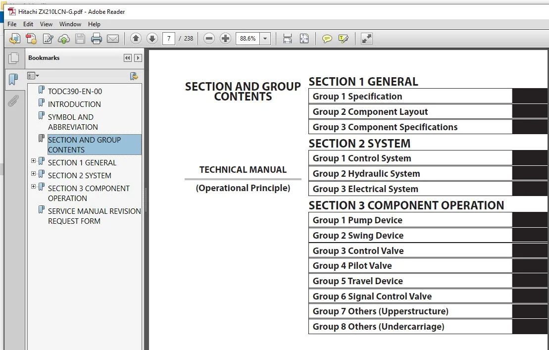
TODC390-EN-00............................................................................................................................................................  1
INTRODUCTION.............................................................................................................................................................  3
SYMBOL AND ABBREVIATION..................................................................................................................................................  5
SECTION AND GROUP CONTENTS...............................................................................................................................................  7
SECTION 1 GENERAL........................................................................................................................................................  9
	Group 1 Specifications............................................................................................................................................... 11
		Specifications................................................................................................................................................... 11
		Working Ranges................................................................................................................................................... 12
	Group 2 Component Layout............................................................................................................................................. 13
		Main Component................................................................................................................................................... 13
		Electrical Component Layout (Overview)........................................................................................................................... 14
		Electrical System (Relays and Related Equipment)................................................................................................................. 15
		Electrical System (Monitors and Switches)........................................................................................................................ 16
		Pump Device...................................................................................................................................................... 17
		Swing Device..................................................................................................................................................... 17
		Control Valve.................................................................................................................................................... 18
		Signal Control Valve............................................................................................................................................. 18
		Solenoid Valve Unit.............................................................................................................................................. 18
		Travel Device.................................................................................................................................................... 19
	Group 3 Component Specifications..................................................................................................................................... 21
		Engine........................................................................................................................................................... 21
		Engine Accessories............................................................................................................................................... 25
		Hydraulic Component.............................................................................................................................................. 26
		Electrical Component............................................................................................................................................. 30
SECTION 2 SYSTEM......................................................................................................................................................... 33
	Group 1 Control System............................................................................................................................................... 35
		Outline.......................................................................................................................................................... 35
		Engine Control................................................................................................................................................... 36
		Pump Control..................................................................................................................................................... 57
		Speed Sensing Control............................................................................................................................................ 58
		Valve Control.................................................................................................................................................... 66
		Other Controls................................................................................................................................................... 78
	Group 2 Hydraulic System............................................................................................................................................. 81
		Outline.......................................................................................................................................................... 81
		Pilot Circuit.................................................................................................................................................... 82
		Main Circuit..................................................................................................................................................... 92
	Group 3 Electrical System............................................................................................................................................103
		Outline..........................................................................................................................................................103
		Main Circuit.....................................................................................................................................................104
		Electric Power Circuit (Key Switch: OFF).........................................................................................................................105
		Indicator Light Check Circuit (Key Switch: ON)...................................................................................................................106
		Accessory Circuit................................................................................................................................................107
		Preheat Circuit (Key Switch: ON/START)...........................................................................................................................108
		Starting Circuit (Key Switch: START).............................................................................................................................110
		Charging Circuit (Key Switch: ON)................................................................................................................................113
		Surge Voltage Prevention Circuit.................................................................................................................................116
		Engine Stop Circuit..............................................................................................................................................118
SECTION 3 COMPONENT OPERATION............................................................................................................................................121
	Group 1 Pump Device..................................................................................................................................................123
		Outline..........................................................................................................................................................123
		Main Pump........................................................................................................................................................124
		Regulator........................................................................................................................................................128
		Solenoid Valve...................................................................................................................................................144
		Pilot Pump.......................................................................................................................................................146
		N Sensor (Engine Speed Sensor)...................................................................................................................................146
		Pump Delivery Pressure Sensor....................................................................................................................................146
		Pump Control Pressure Sensor.....................................................................................................................................147
	Group 2 Swing Device.................................................................................................................................................149
		Outline..........................................................................................................................................................149
		Swing Reduction Gear.............................................................................................................................................150
		Swing Motor......................................................................................................................................................151
		Swing Parking Brake..............................................................................................................................................152
		Valve Unit.......................................................................................................................................................153
	Group 3 Control Valve................................................................................................................................................155
		Outline..........................................................................................................................................................155
		Hydraulic Circuit................................................................................................................................................166
		Flow Combiner Valve..............................................................................................................................................170
		Main Relief Valve................................................................................................................................................172
		Overload Relief Valve (with Make-Up Function)....................................................................................................................174
		Regenerative Valve...............................................................................................................................................176
		Arm Regenerative Valve...........................................................................................................................................178
		Anti-Drift Valve.................................................................................................................................................180
		Flow Rate Control Valve..........................................................................................................................................182
		Auxiliary Flow Combiner Valve and Bypass Shut-Out Valve..........................................................................................................184
	Group 4 Pilot Valve..................................................................................................................................................187
		Outline..........................................................................................................................................................187
		Operation........................................................................................................................................................190
		Shockless Function (Only For Travel Pilot Valve).................................................................................................................196
	Group 5 Travel Device................................................................................................................................................197
		Outline..........................................................................................................................................................197
		Travel Reduction Gear............................................................................................................................................198
		Travel Motor.....................................................................................................................................................199
		Parking Brake....................................................................................................................................................201
		Travel Brake Valve...............................................................................................................................................203
		Overload Relief Valve............................................................................................................................................207
		Travel Mode Control..............................................................................................................................................209
	Group 6 Signal Control Valve.........................................................................................................................................213
		Outline..........................................................................................................................................................213
		Pilot Port.......................................................................................................................................................214
		Shuttle Valve....................................................................................................................................................218
		Shockless Valve..................................................................................................................................................222
		Pump 1 and Pump 2 Flow Rate Control Valves.......................................................................................................................224
		Bucket Flow Rate Control Valve Control Spool, Flow Combiner Valve Control Spool, Swing Parking Brake Release Spool, Arm Flow Rate Control Valve Control Spool....226
	Group 7 Others (Upperstructure)......................................................................................................................................227
		Pilot Shut-Off Valve.............................................................................................................................................227
		Solenoid Valve Unit..............................................................................................................................................228
		Pilot Relief Valve...............................................................................................................................................230
		EC Motor.........................................................................................................................................................230
	Group 8 Others (Undercarriage).......................................................................................................................................231
		Swing Bearing....................................................................................................................................................231
		Center Joint.....................................................................................................................................................232
		Track Adjuster...................................................................................................................................................233
SERVICE MANUAL REVISION REQUEST FORM.....................................................................................................................................237
Please Note:
⦁ This is the same manual used by the DEALERSHIPS to SERVICE your vehicle.
⦁ The manual can be all yours – Once payment is complete, you will be taken to the download page from where you can download the manual. All in 2-5 minutes time!!
⦁ Need any other service / repair / parts manual, please feel free to contact us at heydownloadss @gmail.com . We may surprise you with a nice offer