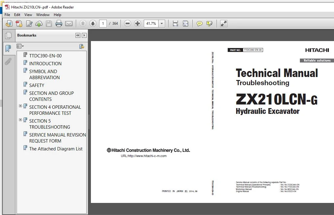
Hitachi ZX210LCN-G Hydraulic Excavator Troubleshooting Technical Manual (TTDC390-EN-00) – PDF Download
Original price was: $59.95.$23.95Current price is: $23.95.
- Hitachi ZX210LCN-G Hydraulic Excavator Troubleshooting Technical Manual
- Part No:TTDC390-EN-00
Description
Hitachi ZX210LCN-G Hydraulic Excavator Troubleshooting Technical Manual (TTDC390-EN-00)
File Details:
Hitachi ZX210LCN-G Hydraulic Excavator Troubleshooting Technical Manual (TTDC390-EN-00)
- Manual Language:English
- Pages: 364
- Size: 3.94 MB
- Downloadable:Yes
- Format:PDF
HITACHI ZX210LCN-G HYDRAULIC EXCAVATOR TROUBLESHOOTING TECHNICAL MANUAL (TTDC390-EN-00) – PDF DOWNLOAD:
Image Preview:
Description:
Hitachi ZX210LCN-G Hydraulic Excavator Troubleshooting Technical Manual (TTDC390-EN-00)
TO THE READER
This manual is written for an experienced technician to provide technical information needed to maintain and repair this machine. The machine specification and description according to destination may be explained on this manual.
• Be sure to thoroughly read this manual for correct product information and service procedures.
• If you have any questions or comments, at if you found any errors regarding the contents of this manual, please contact using “Service Manual Revision Request Form” at the end of this manual.
ADDITIONAL REFERENCES
Please refer to the other materials (operator’s manual, parts catalog, engine technical material and Hitachi training material etc.) in addition to this manual.
MANUAL COMPOSITION
This manual consists the Technical Manual and the Workshop Manual.
• Information included in the Technical Manual: technical information needed for redelivery and delivery, operation and activation of all devices and systems, operational performance tests, and troubleshooting procedures.
• Information included in the Workshop Manual: technical information needed for maintenance and repair of the machine, tools and devices needed for maintenance and repair, maintenance standards, and removal/installation and assemble/ disassemble procedures.
Table Of Contents:
Hitachi ZX210LCN-G Hydraulic Excavator Troubleshooting Technical Manual (TTDC390-EN-00)
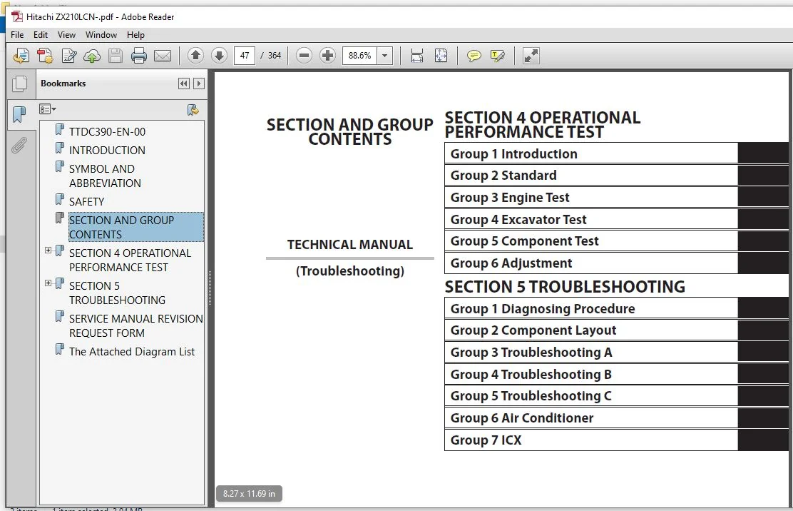
TTDC390-EN-00.......................................................................................................  1
INTRODUCTION........................................................................................................  3
SYMBOL AND ABBREVIATION.............................................................................................  5
SAFETY..............................................................................................................  7
SECTION AND GROUP CONTENTS.......................................................................................... 47
SECTION 4 OPERATIONAL PERFORMANCE TEST.............................................................................. 49
	Group 1 Introduction............................................................................................ 51
		Operational Performance Tests............................................................................... 51
		Preparation for Performance Tests........................................................................... 52
	Group 2 Standard................................................................................................ 53
		Operational Performance Standard Table...................................................................... 53
		Main Pump P-Q Diagram....................................................................................... 58
		Injection Pump.............................................................................................. 60
		Sensor Activating Range..................................................................................... 61
		MPDr. Monitor Indicating Values............................................................................. 62
	Group 3 Engine Test............................................................................................. 67
		Engine Speed................................................................................................ 67
		Engine Compression Pressure................................................................................. 70
		Valve Clearance Adjustment.................................................................................. 72
		Nozzle Check................................................................................................ 74
		Injection Timing............................................................................................ 76
		Lubricant Consumption....................................................................................... 78
	Group 4 Machine Performance Test................................................................................ 79
		Travel Speed................................................................................................ 79
		Track Revolution Speed...................................................................................... 80
		Mistrack Check.............................................................................................. 81
		Travel Parking Leakage...................................................................................... 82
		Swing Speed................................................................................................. 83
		Swing Function Drift Check.................................................................................. 84
		Swing Motor Leakage......................................................................................... 86
		Maximum Swingable Slant Angle............................................................................... 88
		Swing Bearing Play.......................................................................................... 90
		Hydraulic Cylinder Cycle Time............................................................................... 92
		Dig Function Drift Check.................................................................................... 94
		Control Lever Operating Force............................................................................... 97
		Control Lever Stroke........................................................................................ 98
		Combined Operation of Boom Raise / Swing Function Check..................................................... 99
		Combined Operation of Boom Raise / Arm Roll-In Function Check...............................................100
	Group 5 Component Test..........................................................................................101
		Primary Pilot Pressure......................................................................................101
		Secondary Pilot Pressure....................................................................................103
		Solenoid Valve Set Pressure.................................................................................104
		Main Pump Delivery Pressure.................................................................................106
		Main Relief Set Pressure....................................................................................108
		Relief pressure (when relieving swing)......................................................................112
		Relief Pressure (When relieving Travel).....................................................................113
		Overload Relief Valve Set Pressure..........................................................................114
		Main Pump Flow Rate Measurement.............................................................................116
		Swing Motor Drainage........................................................................................124
		Travel Motor Drainage.......................................................................................126
	Group 6 Adjustment..............................................................................................129
		Engine Speed Adjustment and Engine Learning.................................................................129
		Governor Lever and Fuel Cut Lever Position..................................................................132
SECTION 5 TROUBLESHOOTING...........................................................................................137
	Group 1 Diagnosing Procedure....................................................................................139
		Introduction................................................................................................139
		Diagnosis Procedure.........................................................................................140
		Built-In Diagnosing System Operation........................................................................143
		Built-In Diagnosing Function Display List...................................................................144
		Adjustment Data List........................................................................................145
		Electric System Inspection..................................................................................146
		Precautions for Inspection and Maintenance..................................................................147
		Instructions for Disconnecting Connectors...................................................................149
		Fuse Inspection.............................................................................................150
		Fusible Link Inspection.....................................................................................152
		Battery Voltage Check.......................................................................................153
		Alternator Check............................................................................................154
		Continuity Check............................................................................................155
		Voltage and Current Measurement.............................................................................156
		Check by False Signal.......................................................................................161
		Test Harness................................................................................................162
	Group 2 Component Layout........................................................................................165
		Main Component Layout.......................................................................................165
		Electrical Component Layout (Overview)......................................................................166
		Electrical System (Relays and Related Equipment)............................................................167
		Electrical System (Monitors and Switches)...................................................................168
		Pump Device.................................................................................................169
		Swing Device................................................................................................169
		Control Valve...............................................................................................170
		Signal Control Valve........................................................................................170
		Solenoid Valve Unit.........................................................................................170
		Travel Device...............................................................................................171
		Components In Control Valve.................................................................................172
		Signal Control Valve Port Location..........................................................................182
	Group 3 Troubleshooting A.......................................................................................187
		Troubleshooting A (Base Machine Diagnosis By Using Fault Codes) Procedure...................................187
		MC Fault Code List..........................................................................................189
		MC Fault Codes 01 to 03.....................................................................................191
		MC Fault Code 04............................................................................................192
		MC Fault Code 06............................................................................................194
		MC Fault Code 07............................................................................................195
		MC Fault Codes 10, 11.......................................................................................196
		MC Fault Codes 12, 13.......................................................................................197
		MC Fault Codes 14 to 16.....................................................................................198
		MC Fault Code 18............................................................................................199
		MC Fault Code 19............................................................................................200
	Group 4 Troubleshooting B.......................................................................................201
		Troubleshooting B (Machine Diagnosis by Using Troubleshooting Symptom) Procedure............................201
		Relationship between Machine Trouble Symptoms and Related Parts.............................................203
		Correlation between Trouble Symptoms and Part Failures......................................................221
		Engine System Troubleshooting...............................................................................236
		All Actuator System Troubleshooting.........................................................................255
		Front Attachment System Troubleshooting.....................................................................261
		Swing System Troubleshooting................................................................................270
		Travel System Troubleshooting...............................................................................272
		Other System Troubleshooting................................................................................278
		Exchange Inspection.........................................................................................280
		How to Lower Boom in Case of Emergency and When Engine Stops................................................282
	Group 5 Troubleshooting C.......................................................................................283
		Troubleshooting C (Monitor Diagnosis) Procedure.............................................................283
		Malfunction of Monitor Buzzer...............................................................................285
		Malfunction of Coolant Temperature Gauge....................................................................286
		Malfunction of Fuel Gauge...................................................................................287
		Malfunction of Hour Meter...................................................................................289
		Malfunction of Light Bulb Check System......................................................................290
		Malfunction of Fuel Level Indicator.........................................................................291
		Malfunction of Air Filter Restriction Indicator.............................................................292
		Malfunction of Overheat Indicator...........................................................................293
		Malfunction of Engine Oil Pressure Indicator................................................................294
		Malfunction of Alternator Indicator.........................................................................295
		Malfunction of Preheat Indicator............................................................................296
		Malfunction of Hydraulic Oil Filter Restriction Indicator (OP)..............................................297
		Malfunction of LCD..........................................................................................298
		Malfunction of Auto-Idle Indicator..........................................................................299
		Malfunction of Auto-Acceleration Indicator..................................................................300
	Group 6 Air Conditioner.........................................................................................301
		Outline.....................................................................................................301
		Functions of Main Parts.....................................................................................304
		Self-Diagnosing Function....................................................................................309
		Troubleshooting.............................................................................................316
		Air Conditioner Controller Fault Code List..................................................................317
		Air Conditioner Controller Fault Codes 21 to 22.............................................................318
		Air Conditioner Controller Fault Codes 23 to 26.............................................................319
		Work after Replacing Components.............................................................................340
		Refill Compressor Oil.......................................................................................341
		Charge Air Conditioner with Refrigerant.....................................................................342
		Hose and Pipe Tightening Torque.............................................................................350
	Group 7 ICX.....................................................................................................351
		Outline.....................................................................................................351
		ICX Fault Code List.........................................................................................356
		Fault Code 1 to 4 and 6.....................................................................................357
		Fault Code 7................................................................................................357
		Fault Code 8................................................................................................357
		Fault Code 10...............................................................................................357
		Some Parts of Data In Daily Report, Frequency Distribution, Cumulative Operation Hours are Not Recorded.....358
SERVICE MANUAL REVISION REQUEST FORM................................................................................363
The Attached Diagram List...........................................................................................364
Please Note:
⦁ This is the SAME MANUAL used by the dealerships to diagnose your vehicle
⦁ No waiting for couriers / posts as this is a PDF manual and you can download it within 2 minutes time once you make the payment.
⦁ Your payment is all safe and the delivery of the manual is INSTANT – You will be taken to the DOWNLOAD PAGE.
⦁ So have no hesitations whatsoever and write to us about any queries you may have : heydownloadss @gmail.com