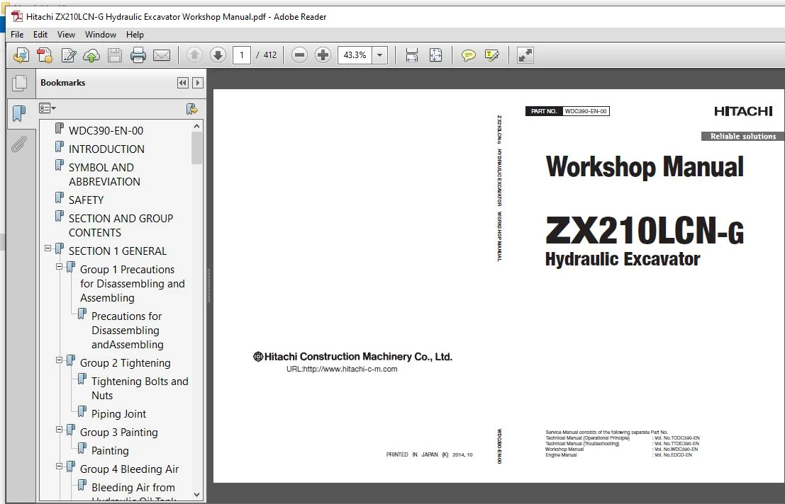
Hitachi ZX210LCN-G Hydraulic Excavator Workshop Manual – Hitachi ZX210LCN-G – PDF Download
Original price was: $87.95.$26.95Current price is: $26.95.
- Hitachi ZX210LCN-G Hydraulic Excavator Workshop Manual
- Part No:WDC390-EN-00
Description
Hitachi ZX210LCN-G Hydraulic Excavator Workshop Manual – Hitachi ZX210LCN-G
File Details:
Hitachi ZX210LCN-G Hydraulic Excavator Workshop Manual – Hitachi ZX210LCN-G
- Manual Language:English
- Pages: 412
- Size: 6.55 MB
- Downloadable:Yes
- Format:PDF
HITACHI ZX210LCN-G HYDRAULIC EXCAVATOR WORKSHOP MANUAL – HITACHI ZX210LCN-G – PDF DOWNLOAD:
Image Preview:
Description:
Hitachi ZX210LCN-G Hydraulic Excavator Workshop Manual – Hitachi ZX210LCN-G
TO THE READER
This manual is written for an experienced technician to provide technical information needed to maintain and repair this machine. The machine specification and description according to destination may be explained on this manual.
• Be sure to thoroughly read this manual for correct product information and service procedures.
• If you have any questions or comments, at if you found any errors regarding the contents of this manual, please contact using “Service Manual Revision Request Form” at the end of this manual.
ADDITIONAL REFERENCES
Please refer to the other materials (operator’s manual, parts catalog, engine technical material and Hitachi training material etc.) in addition to this manual.
MANUAL COMPOSITION
This manual consists the Technical Manual and the Workshop Manual.
• Information included in the Technical Manual: technical information needed for redelivery and delivery, operation and activation of all devices and systems, operational performance tests, and troubleshooting procedures.
• Information included in the Workshop Manual: technical information needed for maintenance and repair of the machine, tools and devices needed for maintenance and repair, maintenance standards, and removal/installation and assemble/ disassemble procedures.
Table Of Contents:
Hitachi ZX210LCN-G Hydraulic Excavator Workshop Manual – Hitachi ZX210LCN-G
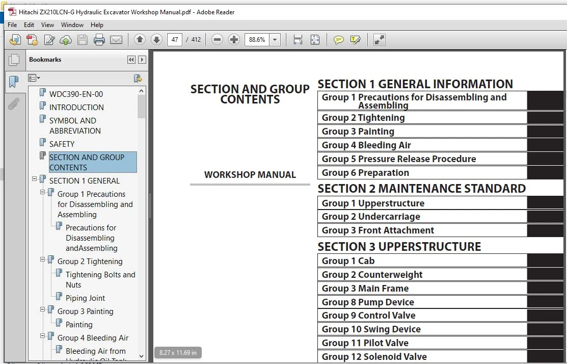
WDC390-EN-00.......................................................  1
INTRODUCTION.......................................................  3
SYMBOL AND ABBREVIATION............................................  5
SAFETY.............................................................  7
SECTION AND GROUP CONTENTS......................................... 47
SECTION 1 GENERAL.................................................. 49
	Group 1 Precautions for Disassembling and Assembling........... 51
		Precautions for Disassembling andAssembling................ 51
	Group 2 Tightening............................................. 57
		Tightening Bolts and Nuts.................................. 57
		Piping Joint............................................... 60
	Group 3 Painting............................................... 65
		Painting................................................... 65
	Group 4 Bleeding Air........................................... 67
		Bleeding Air from Hydraulic Oil Tank....................... 67
		Bleeding Air from Hydraulic System......................... 68
		Bleeding Air from Fuel System.............................. 69
		Bleeding Air from Radiator................................. 71
	Group 5 Pressure Release Procedure............................. 73
		Hydraulic Circuit Pressure Release Procedure............... 73
	Group 6 Preparation............................................ 75
		Preparation before Inspection and Maintenance.............. 75
SECTION 2 MAINTENANCE STANDARD..................................... 79
	Group 1 Upperstructure......................................... 81
		Pump Device................................................ 81
		Swing Motor................................................ 83
	Group 2 Undercarriage.......................................... 87
		Travel Motor............................................... 87
		Sprocket................................................... 89
		Front Idler................................................ 91
		Upper Roller............................................... 93
		Lower Roller............................................... 94
		Track...................................................... 95
	Group 3 Front Attachment....................................... 99
		Pin and Bushing............................................ 99
		Side Cutter (2014503, 2014504).............................101
		Point (4427919)............................................102
		Standard Dimensions for Arm and Bucket Connection..........103
		Standard Dimensions for Arm and Boom Connection............104
		Cylinder...................................................105
SECTION 3 UPPERSTRUCTURE...........................................109
	Group 1 Cab....................................................111
		Removal and Installation of Cab............................111
		Dimensions of The Cab Glass................................121
	Group 2 Counterweight..........................................131
		Removal and Installation of Counterweight..................131
	Group 3 Main Frame.............................................133
		Removal and Installation of Main Frame.....................133
	Group 8 Pump Device............................................139
		Removal and Installation of Pump Device....................139
		Disassembly of Pump Device.................................149
		Assembly of Pump Device....................................156
		Disassembly of Regulator...................................167
		Assembly of Regulator......................................169
		Disassembly of Solenoid Valve..............................171
		Assembly of Solenoid Valve.................................173
		Structure of Pilot Pump....................................175
	Group 9 Control Valve..........................................177
		Removal and Installation Control Valve.....................177
		Disassembly of Housing.....................................187
		Assembly of Housing........................................189
		Disassembly of Control Valve (4-Spool Side)................191
		Assembly of Control Valve (4-Spool Side)...................200
		Disassembly of Control Valve (5-Spool Side)................209
		Assembly of Control Valve (5-Spool Side)...................218
	Group 10 Swing Device..........................................227
		Removal and Installation of Swing Device...................227
		Disassembly of Swing Device................................231
		Assembly of Swing Device...................................236
	Group 11 Pilot Valve...........................................243
		Removal and Installation of Pilot Valve (Left).............243
		Removal and Installation of Pilot Valve (Right)............249
		Removal and Installation of Travel Pilot Valve.............255
		Disassembly of Pilot Valves (Right and Left)...............259
		Assembly of Pilot Valves (Right and Left)..................262
		Disassembly of Travel Pilot Valve..........................265
		Assembly of Travel Pilot Valve.............................269
	Group 12 Pilot Shut-Off Valve..................................275
		Removal and Installation of Pilot Shut-Off Valve...........275
		Removal and Installation of 3-Spool Solenoid Valve Unit....279
	Group 13 Signal Control Valve..................................283
		Removal and Installation of Signal Control Valve...........283
SECTION 4 UNDERCARRIAGE............................................287
	Group 1 Swing Bearing..........................................289
		Removal and Installation of Swing Bearing..................289
		Disassembly of Swing Bearing...............................293
		Assembly of Swing Bearing..................................296
	Group 2 Travel Device..........................................299
		Removal and Installation of Travel Device..................299
		Disassembly of Travel Device...............................303
		Assembly of Travel Device..................................307
		Disassembly of Brake Valve.................................315
		Assembly of Brake Valve....................................317
		Precautions for Using Floating Seal........................319
	Group 3 Center Joint...........................................323
		Disassembly of Center Joint................................323
		Assembly of Center Joint...................................325
		Replacement of Body and Spindle............................328
	Group 4 Track Adjuster.........................................329
		Removal and Installation of Track Adjuster.................329
		Disassembly of Front Idler.................................333
		Assembly of Front Idler....................................336
		Disassembly of Track Adjuster..............................339
		Assembly of Track Adjuster.................................343
		Precautions for Using Floating Seal........................347
	Group 5 Upper and Lower Rollers................................349
		Removal and Installation of Upper Roller...................349
		Removal and Installation of Lower Roller...................353
		Disassembly of Lower Roller................................359
		Assembly of Lower Roller...................................361
		Precautions for Using Floating Seal........................363
	Group 6 Track..................................................365
		Removal and Installation of Track..........................365
SECTION 5 FRONT ATTACHMENT.........................................373
	Group 1 Front Attachment.......................................375
		Removal and Installation of Front Attachment...............375
	Group 2 Cylinder...............................................381
		Removal and Installation of Boom Cylinder..................381
		Removal and Installation of Arm Cylinder...................385
		Removal and Installation of Bucket Cylinder................391
		Disassembly of Boom, Arm Cylinder..........................395
		Assembly of Boom, Arm Cylinder.............................399
		Disassembly of Bucket Cylinder.............................403
		Assembly of Bucket Cylinder................................406
SERVICE MANUAL REVISION REQUEST FORM...............................411
Please Note:
⦁ This is the SAME MANUAL used by the dealerships to diagnose your vehicle
⦁ No waiting for couriers / posts as this is a PDF manual and you can download it within 2 minutes time once you make the payment.
⦁ Your payment is all safe and the delivery of the manual is INSTANT – You will be taken to the DOWNLOAD PAGE.
⦁ So have no hesitations whatsoever and write to us about any queries you may have : heydownloadss @gmail.com