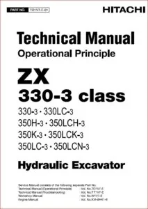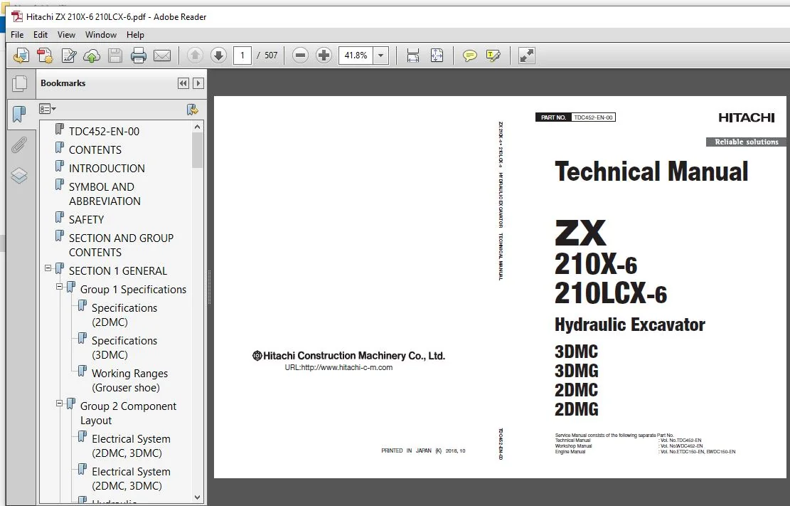
Hitachi ZX210X-6 210LCX-6 Hydraulic Excavator Technical Manual – Hitachi ZX210X-6 210LCX-6 – PDF Download
Original price was: $71.95.$23.95Current price is: $23.95.
- Hitachi ZX210X-6 210LCX-6 Hydraulic Excavator Technical Manual
- Part No:TDC452-EN-00
Description
Hitachi ZX210X-6 210LCX-6 Hydraulic Excavator Technical Manual – Hitachi ZX210X-6 210LCX-6
File Details:
Hitachi ZX210X-6 210LCX-6 Hydraulic Excavator Technical Manual – Hitachi ZX210X-6 210LCX-6
- Manual Language:English
- Pages: 507
- Size:43.5 MB
- Downloadable:Yes
- Format:PDF
HITACHI ZX210X-6 210LCX-6 HYDRAULIC EXCAVATOR TECHNICAL MANUAL – HITACHI ZX210X-6 210LCX-6 – PDF DOWNLOAD:
Image Preview:
Description:
Hitachi ZX210X-6 210LCX-6 Hydraulic Excavator Technical Manual – Hitachi ZX210X-6 210LCX-6
TO THE READER
This manual is written for an experienced technician to provide technical information needed to maintain and repair this machine. The machine specification and description according to destination may be explained on this manual.
• Be sure to thoroughly read this manual for correct product information and service procedures.
• If you have any questions or comments, at if you found any errors regarding the contents of this manual, please contact using “Service Manual Revision Request Form” at the end of this manual.
ADDITIONAL REFERENCES
Please refer to the other materials (operator’s manual, parts catalog, engine technical material and Hitachi training material etc.) in addition to this manual.
MANUAL COMPOSITION
This manual consists the Technical Manual and the Workshop Manual.
• Information included in the Technical Manual: technical information needed for redelivery and delivery, operation and activation of all devices and systems, operational performance tests, and troubleshooting procedures.
• Information included in the Workshop Manual: technical information needed for maintenance and repair of the machine, tools and devices needed for maintenance and repair, maintenance standards, and removal/installation and assemble/ disassemble procedures.
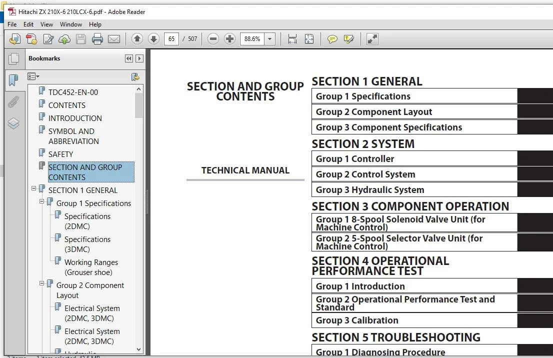
Table Of Contents:
Hitachi ZX210X-6 210LCX-6 Hydraulic Excavator Technical Manual – Hitachi ZX210X-6 210LCX-6
TDC452-EN-00............................................................................  1
CONTENTS................................................................................  3
INTRODUCTION............................................................................ 13
SYMBOL AND ABBREVIATION................................................................. 15
SAFETY.................................................................................. 17
SECTION AND GROUP CONTENTS.............................................................. 65
SECTION 1 GENERAL....................................................................... 67
	Group 1 Specifications.............................................................. 69
		Specifications (2DMC)........................................................... 69
		Specifications (3DMC)........................................................... 70
		Working Ranges (Grouser shoe)................................................... 71
	Group 2 Component Layout............................................................ 73
		Electrical System (2DMC, 3DMC).................................................. 73
		Electrical System (2DMC, 3DMC).................................................. 74
		Hydraulic Component (2DMC, 3DMC)................................................ 75
	Group 3 Component Specifications.................................................... 77
		Hydraulic Component (only for 2DMC, 3DMC)....................................... 77
		Electrical Components (only for 2DMC, 3DMC)..................................... 78
SECTION 2 SYSTEM........................................................................ 81
	Group 1 Controller.................................................................. 83
		Outline......................................................................... 83
		CAN Circuit..................................................................... 86
	Group 2 Control System.............................................................. 89
		Outline......................................................................... 89
		Front Attachment Semiautomatic Control.......................................... 93
		Engine Control (MC, ECM)........................................................101
		Valve Control (MC)..............................................................105
	Group 3 Hydraulic System............................................................111
		Outline.........................................................................111
		Front Attachment Semiautomatic Control Pilot Circuit............................112
SECTION 3 COMPONENT OPERATION...........................................................127
	Group 1 8-Spool Solenoid Valve Unit (for Machine Control)...........................129
		8-Spool Solenoid Valve Unit (for Machine Control)...............................129
	Group 2 5-Spool Selector Valve Unit (for Machine Control)...........................133
		5-Spool Selector Valve Unit (for Machine Control)...............................133
SECTION 4 OPERATIONAL PERFORMANCE TEST..................................................139
	Group 1 Introduction................................................................141
		Outline.........................................................................141
	Group 2 Operational Performance Test and Standard...................................145
		Operational Performance Test and Standard Table.................................145
	Group 3 Calibration.................................................................157
		Accuracy confirmation of 2D.....................................................157
		Operation of the Total Station (TSC3)...........................................176
		Mobile Station GNSS Setting.....................................................182
		Observation of Terrain Feature Points by Mobile Stations........................188
		Accuracy confirmation of 3D.....................................................191
		Bucket Dimension Measurement....................................................200
		Bucket Setting Change Method of Bucket less Machine.............................209
		Laser Catcher Position Accuracy Confirmation....................................213
		3DMG Calibration................................................................228
		MC Solenoid Valve for MC Calibration............................................244
		Bleed Air from Solenoid Valve of MC.............................................259
		[Setting Method] Gradient in Front/Back Direction (Horizontal surface/Slope)....273
		[Setting Method] Gradient in Left/Right Direction (Horizontal surface/Slope)....279
		[Setting Method] Altitude Offset................................................283
		Wi-Fi Network...................................................................287
		Metering Calibration............................................................289
		MC Accuracy Check...............................................................321
SECTION 5 TROUBLESHOOTING...............................................................351
	Group 1 Diagnosing Procedure........................................................353
		Introduction....................................................................353
	Group 2 Troubleshooting A...........................................................355
		Troubleshooting A (Base Machine Diagnosis by Using Fault Codes) Procedure.......355
		Computer Aided Construction Controller (CAC Controller) Fault Code List.........357
		CAC Controller Fault Code 19001 to 19002........................................369
		CAC Controller Fault Code 19003.................................................370
		CAC Controller Fault Code 19031 to 19033........................................371
		CAC Controller Fault Code 19034 to 19039........................................372
		CAC Controller Fault Code 19040 to 19042........................................373
		CAC Controller Fault Code 19045 to 19046........................................374
		CAC Controller Fault Code 19047.................................................375
		CAC Controller Fault Code 19081.................................................376
		CAC Controller Fault Code 19120.................................................377
		CAC Controller Fault Code 19121.................................................378
		CAC Controller Fault Code 19122.................................................379
		CAC Controller Fault Code 19123.................................................380
		CAC Controller Fault Code 19125.................................................381
		CAC Controller Fault Code 19127.................................................382
		CAC Controller Fault Code 19128.................................................383
		CAC Controller Fault Code 19130.................................................384
		CAC Controller Fault Code 19015 to 19017........................................385
		CAN1 (CAC) Harness Check........................................................386
		CAC Controller Fault Code 19022 to 19028........................................389
		2DCAN (2D System) Harness Check.................................................390
		3DCAN (3D System) Harness Check.................................................392
		CAC Controller Fault Code 19051.................................................394
	Group 3 Troubleshooting B...........................................................395
		Troubleshooting B (Machine Diagnosis by Using Trouble Symptom) Procedure........395
		Relationship between Machine Trouble Symptoms and Related Parts.................397
		Correlation between Trouble Symptoms and Part Failures..........................403
		Questionnaire...................................................................467
		[Check Procedure 1] Software version............................................471
		[Check Procedure 2] GNSS, Design................................................474
		[Check Procedure 3] Bucket weight setting.......................................477
		Bucket Weight Setting...........................................................477
		[Check Procedure 4] Tooth length................................................478
		[Check Procedure 5] Correction..................................................483
		[Check Procedure 6] GNSS information............................................487
		[Check Procedure 7] GNSS accuracy tolerance setting.............................490
		[Check Procedure 8] Radio condition.............................................496
	Group 4 Troubleshooting C...........................................................499
		Machine Diagnosis by Using Machine Guidance System Status Indicator.............499
SERVICE MANUAL REVISION REQUEST FORM....................................................505
The Attached Diagram List...............................................................506
Please Note:
⦁ This is the same manual used by the dealers to diagnose and troubleshoot your vehicle
⦁ You will be directed to the download page as soon as the purchase is completed. The whole payment and downloading process will take anywhere between 2-5 minutes
⦁ Need any other service / repair / parts manual, please feel free to contact [email protected] . We still have 50,000 manuals unlisted