Hitachi ZX240-5A 240LC-5A 250H-5A 250LCH-5A 250K-5A 250LCK-5A Hydraulic Excavator Troubleshooting Technical Manual – PDF Download
Original price was: $88.95.$25.95Current price is: $25.95.
- Hitachi ZX240-5A 240LC-5A 250H-5A 250LCH-5A 250K-5A 250LCK-5A Hydraulic Excavator Troubleshooting Technical Manual
- Part No:TTDCY90-EN-00
Description
Hitachi ZX240-5A 240LC-5A 250H-5A 250LCH-5A 250K-5A 250LCK-5A Hydraulic Excavator Troubleshooting Technical Manual
File Details:
Hitachi ZX240-5A 240LC-5A 250H-5A 250LCH-5A 250K-5A 250LCK-5A Hydraulic Excavator Troubleshooting Technical Manual
- Manual Language:English
- Pages: 470
- Size: 10.2 MB
- Downloadable:Yes
- Format:PDF
HITACHI ZX240-5A 240LC-5A 250H-5A 250LCH-5A 250K-5A 250LCK-5A HYDRAULIC EXCAVATOR TROUBLESHOOTING TECHNICAL MANUAL – PDF DOWNLOAD:
Image Preview:
Description:
Hitachi ZX240-5A 240LC-5A 250H-5A 250LCH-5A 250K-5A 250LCK-5A Hydraulic Excavator Troubleshooting Technical Manual
TO THE READER
This manual is written for an experienced technician to provide technical information needed to maintain and repair this machine. The machine specification and description according to destination may be explained on this manual.
• Be sure to thoroughly read this manual for correct product information and service procedures.
• If you have any questions or comments, at if you found any errors regarding the contents of this manual, please contact using “Service Manual Revision Request Form” at the end of this manual.
ADDITIONAL REFERENCES
Please refer to the other materials (operator’s manual, parts catalog, engine technical material and Hitachi training material etc.) in addition to this manual.
MANUAL COMPOSITION
This manual consists the Technical Manual and the Workshop Manual.
• Information included in the Technical Manual: technical information needed for redelivery and delivery, operation and activation of all devices and systems, operational performance tests, and troubleshooting procedures.
• Information included in the Workshop Manual: technical information needed for maintenance and repair of the machine, tools and devices needed for maintenance and repair, maintenance standards, and removal/installation and assemble/ disassemble procedures.
Table Of Contents:
Hitachi ZX240-5A 240LC-5A 250H-5A 250LCH-5A 250K-5A 250LCK-5A Hydraulic Excavator Troubleshooting Technical Manual
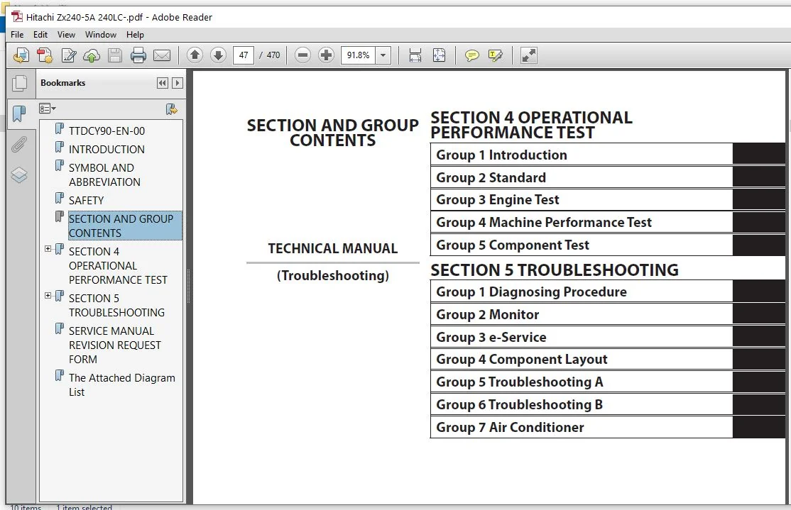
TTDCY90-EN-00..............................................................................  1
INTRODUCTION...............................................................................  3
SYMBOL AND ABBREVIATION....................................................................  5
SAFETY.....................................................................................  7
SECTION AND GROUP CONTENTS................................................................. 47
SECTION 4 OPERATIONAL PERFORMANCE TEST..................................................... 49
	Group 1 Introduction................................................................... 51
		Operational Performance Tests...................................................... 51
		Preparation for Performance Tests.................................................. 52
	Group 2 Standard....................................................................... 53
		Operational Performance Standard Table............................................. 53
		Main Pump P-Q Diagram (P1, P2)..................................................... 62
		Sensor Activating Range............................................................ 64
		MPDr. Monitor Indicating Values.................................................... 66
	Group 3 Engine Test.................................................................... 79
		Engine Speed....................................................................... 79
		Lubricant Consumption.............................................................. 82
	Group 4 Machine Performance Test....................................................... 83
		Travel Speed....................................................................... 83
		Track Revolution Speed............................................................. 84
		Mistrack Check..................................................................... 85
		Travel Parking Leakage............................................................. 86
		Swing Speed........................................................................ 87
		Swing Function Drift Check......................................................... 88
		Swing Motor Leakage................................................................ 90
		Maximum Swingable Slant Angle...................................................... 92
		Swing Bearing Play................................................................. 94
		Hydraulic Cylinder Cycle Time...................................................... 96
		Dig Function Drift Check........................................................... 98
		Control Lever Operating Force......................................................101
		Control Lever Stroke...............................................................102
		Combined Operation of Boom Raise/Swing Function Check..............................103
		Combined Operation of Boom Raise/Arm Roll-In Function Check........................104
		Clearance of Front Attachment Connecting Part......................................105
	Group 5 Component Test.................................................................107
		Primary Pilot Pressure.............................................................107
		Secondary Pilot Pressure...........................................................109
		3-Spool Solenoid Valve Set Pressure................................................110
		Main Pump Delivery Pressure........................................................113
		Main Relief Set Pressure...........................................................114
		Relief Pressure (when relieving swing).............................................118
		Overload Relief Valve Set Pressure.................................................120
		Main Pump Flow Rate Measurement....................................................122
		Swing Motor Drainage...............................................................130
		Travel Motor Drainage..............................................................132
SECTION 5 TROUBLESHOOTING..................................................................137
	Group 1 Diagnosing Procedure...........................................................139
		Introduction.......................................................................139
		Diagnosis Procedure................................................................140
		Electric System Inspection.........................................................143
		Precautions for Inspection and Maintenance.........................................144
		Instructions for Disconnecting Connectors..........................................146
		Fuse Inspection....................................................................148
		Fusible Link Inspection............................................................151
		Battery Voltage Check..............................................................152
		Alternator Check...................................................................153
		Continuity Check...................................................................154
		Voltage and Current Measurement....................................................156
		Check by False Signal..............................................................163
		Test Wire Harness..................................................................164
	Group 2 Monitor........................................................................167
		Outline............................................................................167
		Operating Procedures of Service Menu...............................................168
		Setting Menu.......................................................................205
		Inspection of Engine Oil Level, Coolant Level, Hour Meter, and Fuel Gauge..........208
		Fuel Gauge and Coolant Temperature Gauge...........................................209
	Group 3 e-Service......................................................................211
		Outline............................................................................211
		List of Operation Data.............................................................212
		Snapshot Data......................................................................216
		Communication System...............................................................217
	Group 4 Component Layout...............................................................219
		Main Component.....................................................................219
		Electrical System (Overview).......................................................220
		Electrical System (Rear Tray)......................................................221
		Electrical System (Switch Panel)...................................................222
		Electrical System (Around Air Cleaner).............................................223
		Electrical System (Relays, etc.)...................................................224
		Components Related with Engine.....................................................225
		Components Related with Pump Device................................................226
		Around Pump Device.................................................................227
		Components Related with Control Valve..............................................228
		Components Related with Signal Control Valve.......................................228
		Components Related with Swing Device...............................................230
		Travel Device......................................................................230
		3-Spool Solenoid Valve Unit........................................................231
		Layout of Attachment Spec. Parts...................................................232
		Control Valve Side of Hydraulic Oil Tank...........................................234
		Components in Control Valve........................................................238
		Pilot Port.........................................................................258
	Group 5 Troubleshooting A..............................................................263
		Troubleshooting A (Base Machine DiagnosisBy Using Fault Codes) Procedure...........263
		MC Fault Code List.................................................................265
		ECM Fault Code List................................................................276
		Monitor Controller (Monitor) Fault Code List.......................................300
		Monitor Controller (Information) Fault Code List...................................301
		Air Conditioner Controller Fault Code List.........................................304
		Communication Terminal Fault Code List.............................................305
		MC Fault Codes 11000 to 11002......................................................307
		MC Fault Code 11003................................................................308
		MC Fault Codes 11006, 11007,11009..................................................310
		Monitor Controller (Monitor) Fault Codes 13002, 13003, 13005.......................310
		CAN0 Harness Check.................................................................311
		MC Fault Codes 11008, 11010........................................................315
		Monitor Controller (Monitor) Fault Codes 13004, 13006, 13007.......................315
		CAN1 Harness Check.................................................................316
		MC Fault Code 11100................................................................319
		MC Fault Code 11101................................................................320
		MC Fault Codes 11200, 11202........................................................321
		MC Fault Codes 11206, 11208........................................................322
		MC Fault Codes 11301 to 11303......................................................323
		MC Fault Codes 11304, 11307........................................................324
		MC Fault Code 11325................................................................325
		MC Fault Code 11400................................................................326
		MC Fault Code 11401................................................................327
		MC Fault Code 11402................................................................328
		MC Fault Code 11403................................................................329
		MC Fault Code 11407................................................................330
		MC Fault Code 11436................................................................331
		MC Fault Codes 11458, 11459........................................................332
		MC Fault Code 11901................................................................333
		MC Fault Code 20011................................................................334
		MC Fault Code 20062................................................................335
		Monitor Controller (Information) Fault Codes 13304, 13310..........................336
		Monitor Controller (Information) Fault Code 13311..................................337
		Air Conditioner Controller Fault Codes 11 to 22....................................338
		Air Conditioner Controller Fault Codes 43 to 92....................................339
		Monitor Controller (Information) Fault Codes 20100 to 20114........................340
		Monitor Controller (Information) Fault Codes 20109 to 20149........................341
	Group 6 Troubleshooting B..............................................................343
		Troubleshooting B (Machine Diagnosis byUsing Troubleshooting Symptom) Procedure....343
		Relationship between Machine Trouble Symptoms and Related Parts....................345
		Correlation between Trouble Symptoms and Part Failures.............................365
		Engine System Troubleshooting......................................................379
		All Actuator System Troubleshooting................................................387
		Front Attachment System Troubleshooting............................................394
		Swing System Troubleshooting.......................................................406
		Travel System Troubleshooting......................................................408
		Other System Troubleshooting.......................................................413
		Exchange Inspection................................................................418
		How to Lowering Boom in Case of Emergency and When Engine Stops....................421
	Group 7 Air Conditioner................................................................423
		Outline............................................................................423
		Functions of Main Parts............................................................426
		Troubleshooting....................................................................431
		Air Conditioner Controller Fault Code List.........................................432
		Air Conditioner Controller Fault Codes 11 to 22....................................433
		Air Conditioner Controller Fault Codes 43 to 92....................................434
		Work after Replacing Components....................................................456
		Refill Compressor Oil..............................................................457
		Charge Air Conditioner with Refrigerant............................................458
		Hose and Pipe Tightening Torque....................................................466
SERVICE MANUAL REVISION REQUEST FORM.......................................................469
The Attached Diagram List..................................................................470
Please Note:
⦁ This is the SAME manual used by the dealers to troubleshoot any faults in your vehicle. This can be yours in 2 minutes after the payment is made.
⦁ Contact us at [email protected] should you have any queries before your purchase or that you need any other service / repair / parts operators manual.