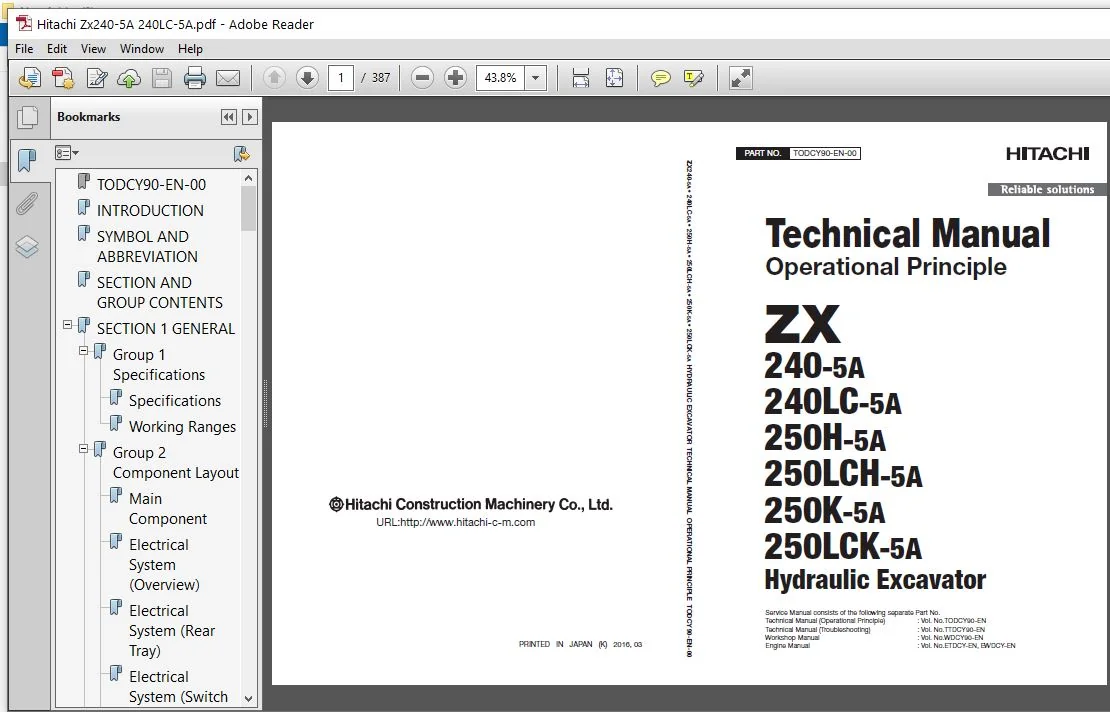
Hitachi ZX240-5A 240LC-5A 250H-5A 250LCH-5A 250K-5A 250LCK-5A Operational Principle Manual – PDF Download
Original price was: $84.95.$26.95Current price is: $26.95.
- Hitachi ZX240-5A 240LC-5A 250H-5A 250LCH-5A 250K-5A 250LCK-5A Operational Principle Manual
- Part No:TODCY90-EN-00
Description
Hitachi ZX240-5A 240LC-5A 250H-5A 250LCH-5A 250K-5A 250LCK-5A Operational Principle Manual
File Details:
Hitachi ZX240-5A 240LC-5A 250H-5A 250LCH-5A 250K-5A 250LCK-5A Operational Principle Manual
- Manual Language:English
- Pages: 387
- Size:37.6 MB
- Downloadable:Yes
- Format:PDF
HITACHI ZX240-5A 240LC-5A 250H-5A 250LCH-5A 250K-5A 250LCK-5A OPERATIONAL PRINCIPLE MANUAL – PDF DOWNLOAD:
Image Preview:
Description:
TO THE READER
This manual is written for an experienced technician to provide technical information needed to maintain and repair this machine. The machine specification and description according to destination may be explained on this manual.
• Be sure to thoroughly read this manual for correct product information and service procedures.
• If you have any questions or comments, at if you found any errors regarding the contents of this manual, please contact using “Service Manual Revision Request Form” at the end of this manual.
ADDITIONAL REFERENCES
Please refer to the other materials (operator’s manual, parts catalog, engine technical material and Hitachi training material etc.) in addition to this manual.
MANUAL COMPOSITION
This manual consists the Technical Manual and the Workshop Manual.
• Information included in the Technical Manual: technical information needed for redelivery and delivery, operation and activation of all devices and systems, operational performance tests, and troubleshooting procedures.
• Information included in the Workshop Manual: technical information needed for maintenance and repair of the machine, tools and devices needed for maintenance and repair, maintenance standards, and removal/installation and assemble/ disassemble procedures.
Table Of Contents:
TODCY90-EN-00..............................................................................................................................................................  1
INTRODUCTION...............................................................................................................................................................  3
SYMBOL AND ABBREVIATION....................................................................................................................................................  5
SECTION AND GROUP CONTENTS.................................................................................................................................................  7
SECTION 1 GENERAL..........................................................................................................................................................  9
	Group 1 Specifications................................................................................................................................................. 11
		Specifications..................................................................................................................................................... 11
		Working Ranges..................................................................................................................................................... 14
	Group 2 Component Layout............................................................................................................................................... 17
		Main Component..................................................................................................................................................... 17
		Electrical System (Overview)....................................................................................................................................... 18
		Electrical System (Rear Tray)...................................................................................................................................... 19
		Electrical System (Switch Panel)................................................................................................................................... 20
		Electrical System (Around Air Cleaner)............................................................................................................................. 21
		Electrical System (Relays, etc.)................................................................................................................................... 22
		Components Related with Engine..................................................................................................................................... 23
		Components Related with Pump Device................................................................................................................................ 24
		Around Pump Device................................................................................................................................................. 25
		Components Related with Control Valve.............................................................................................................................. 26
		Components Related with Signal Control Valve....................................................................................................................... 26
		Components Related with Swing Device............................................................................................................................... 28
		Travel Device...................................................................................................................................................... 28
		3-Spool Solenoid Valve Unit........................................................................................................................................ 29
		Layout of Attachment Spec. Parts................................................................................................................................... 30
		Control Valve Side of Hydraulic Oil Tank........................................................................................................................... 32
	Group 3 Component Specifications....................................................................................................................................... 35
		Engine............................................................................................................................................................. 35
		Engine Accessories................................................................................................................................................. 39
		Hydraulic Component................................................................................................................................................ 40
		Electrical Component............................................................................................................................................... 44
SECTION 2 SYSTEM........................................................................................................................................................... 47
	Group 1 Controller..................................................................................................................................................... 49
		Outline............................................................................................................................................................ 49
		CAN Circuit........................................................................................................................................................ 50
	Group 2 Control System................................................................................................................................................. 53
		Outline............................................................................................................................................................ 53
		Engine Control..................................................................................................................................................... 56
		Pump Control....................................................................................................................................................... 88
		Valve Control (Standard)...........................................................................................................................................102
		Valve Control (Optional)...........................................................................................................................................114
		Other Control......................................................................................................................................................124
	Group 3 ECM System.....................................................................................................................................................133
		Outline............................................................................................................................................................133
		Fuel Injection Control.............................................................................................................................................134
		Fuel Injection Amount Correction Control...........................................................................................................................142
		EGR Control........................................................................................................................................................144
		Preheating Control.................................................................................................................................................146
		Alarm Control......................................................................................................................................................147
	Group 4 Hydraulic System...............................................................................................................................................149
		Outline............................................................................................................................................................149
		Pilot Circuit......................................................................................................................................................150
		Main Circuit.......................................................................................................................................................160
		Breaker/Pulverizer/Crusher Circuit (Optional)......................................................................................................................176
	Group 5 Electrical System..............................................................................................................................................187
		Outline............................................................................................................................................................187
		Main Circuit.......................................................................................................................................................188
		Electric Power Circuit (Key Switch: OFF)...........................................................................................................................190
		CAN Circuit........................................................................................................................................................192
		Accessory Circuit..................................................................................................................................................194
		Starting Circuit (Key Switch: START)...............................................................................................................................196
		Charging Circuit (Key Switch: ON)..................................................................................................................................198
		Surge Voltage Prevention Circuit...................................................................................................................................202
		Pilot Shut-Off Circuit (Key switch: ON)............................................................................................................................204
		Auto Shut-Down Circuit/Automatic Engine Stop Circuit at Low Temperature............................................................................................206
		Engine Stop Circuit................................................................................................................................................208
		Monitor Circuit....................................................................................................................................................211
		Security Circuit...................................................................................................................................................212
		Radio Circuit......................................................................................................................................................214
		Air Conditioner Circuit............................................................................................................................................214
		Accessory Circuit..................................................................................................................................................217
		Work Light Circuit.................................................................................................................................................218
		Wiper/Washer Circuit...............................................................................................................................................220
		Cab Light Circuit..................................................................................................................................................222
SECTION 3 COMPONENT OPERATION..............................................................................................................................................227
	Group 1 Pump Device....................................................................................................................................................229
		Outline............................................................................................................................................................229
		Main Pump..........................................................................................................................................................230
		Regulator..........................................................................................................................................................234
		Solenoid Valve.....................................................................................................................................................252
		Pilot Pump.........................................................................................................................................................254
		Pump Delivery Pressure Sensor......................................................................................................................................254
		Pump Control Pressure Sensor.......................................................................................................................................254
	Group 2 Swing Device...................................................................................................................................................255
		Outline............................................................................................................................................................255
		Swing Reduction Gear...............................................................................................................................................256
		Swing Motor........................................................................................................................................................257
		Swing Parking Brake................................................................................................................................................258
		Valve Unit.........................................................................................................................................................260
	Group 3 Control Valve..................................................................................................................................................263
		Outline............................................................................................................................................................263
		Hydraulic Circuit..................................................................................................................................................284
		Flow Combiner Valve................................................................................................................................................290
		Main Relief Valve..................................................................................................................................................292
		Overload Relief Valve (with Make-Up Function)......................................................................................................................296
		Regenerative Valve.................................................................................................................................................300
		Anti-Drift Valve...................................................................................................................................................304
		Flow Rate Control Valve............................................................................................................................................308
		Digging Regenerative Valve.........................................................................................................................................312
		Boom Lower Meter-In Cut Valve......................................................................................................................................314
		Auxiliary Flow Combiner Valve and Bypass Shut-Out Valve............................................................................................................316
	Group 4 Pilot Valve....................................................................................................................................................321
		Outline............................................................................................................................................................321
		Operation (Front Attachment / Swing and Travel Pilot Valves).......................................................................................................323
		Operation (Auxiliary Pilot Valve)..................................................................................................................................331
		Shockless Function (Only for Travel Pilot Valve)...................................................................................................................336
	Group 5 Travel Device..................................................................................................................................................337
		Outline............................................................................................................................................................337
		Travel Reduction Gear..............................................................................................................................................338
		Travel Motor.......................................................................................................................................................340
		Parking Brake......................................................................................................................................................342
		Travel Brake Valve.................................................................................................................................................344
		Overload Relief Valve..............................................................................................................................................348
		Travel Mode Control................................................................................................................................................350
	Group 6 Signal Control Valve...........................................................................................................................................355
		Outline............................................................................................................................................................355
		Pilot Port.........................................................................................................................................................356
		Shuttle Valve......................................................................................................................................................361
		Shockless Valve....................................................................................................................................................364
		Pump 1 and 2 Flow Rate Control Valve...............................................................................................................................368
		Bucket Flow Rate Control Valve Control Spool, Flow Combiner Valve Control Spool, Swing Parking Brake Release Spool, Arm 1 Flow Rate Control Valve Control Spool....370
	Group 7 Others (Upperstructure)........................................................................................................................................373
		Pilot Shut-Off Solenoid Valve......................................................................................................................................373
		Solenoid Valve.....................................................................................................................................................375
		Pilot Relief Valve.................................................................................................................................................379
		Recirculation Valve (Option).......................................................................................................................................380
	Group 8 Others (Undercarriage).........................................................................................................................................381
		Swing Bearing......................................................................................................................................................381
		Center Joint.......................................................................................................................................................382
		Track Adjuster (Front Idler Integrated Type).......................................................................................................................383
SERVICE MANUAL REVISION REQUEST FORM.......................................................................................................................................387
Please Note:
⦁ This is the SAME exact manual used by your dealers to fix your vehicle.
⦁ The same can be yours in the next 2-3 mins as you will be directed to the download page immediately after paying for the manual.
⦁ Any queries / doubts regarding your purchase, please feel free to contact [email protected]