Hitachi ZX250W-3 Wheeled Material Handler Technical Service Manual – PDF Download
Original price was: $71.95.$26.95Current price is: $26.95.
- Hitachi ZX250W-3 Wheeled Material Handler Technical Service Manual
- Part No:KMCRB-E-00
Description
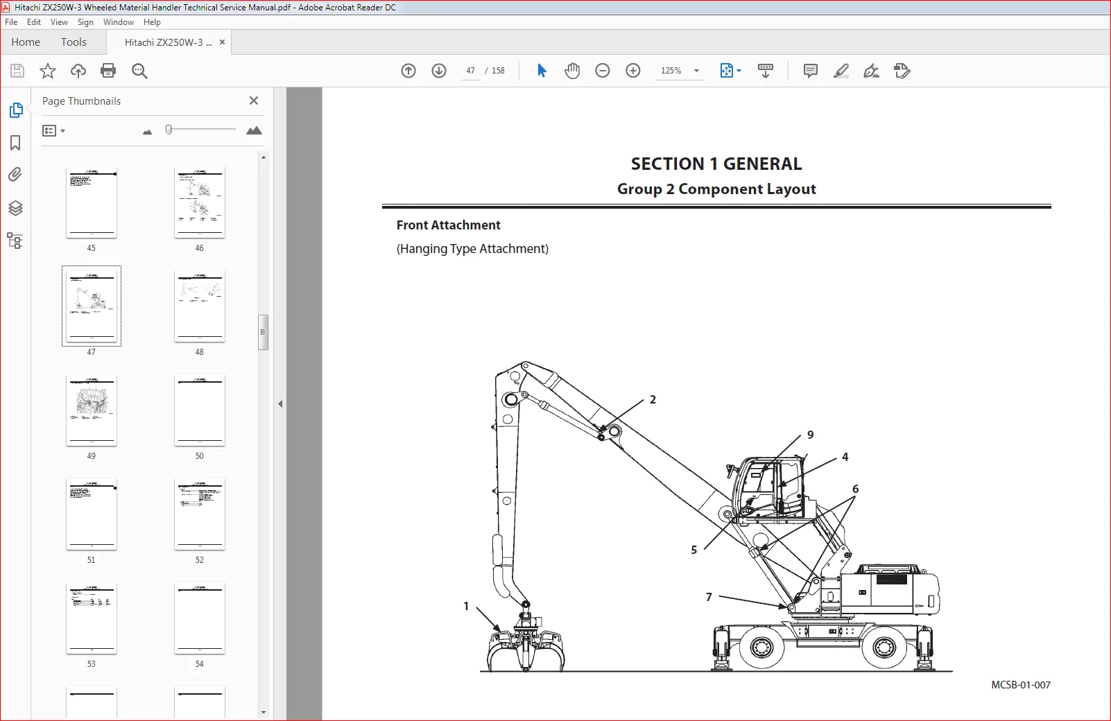
Hitachi ZX250W-3 Wheeled Material Handler Technical Service Manual
File Details:
Hitachi ZX250W-3 Wheeled Material Handler Technical Service Manual
- Manual Language:English
- Downloadable:Yes
- Pages:158
- Size: 5.28 MB
- Format:PDF
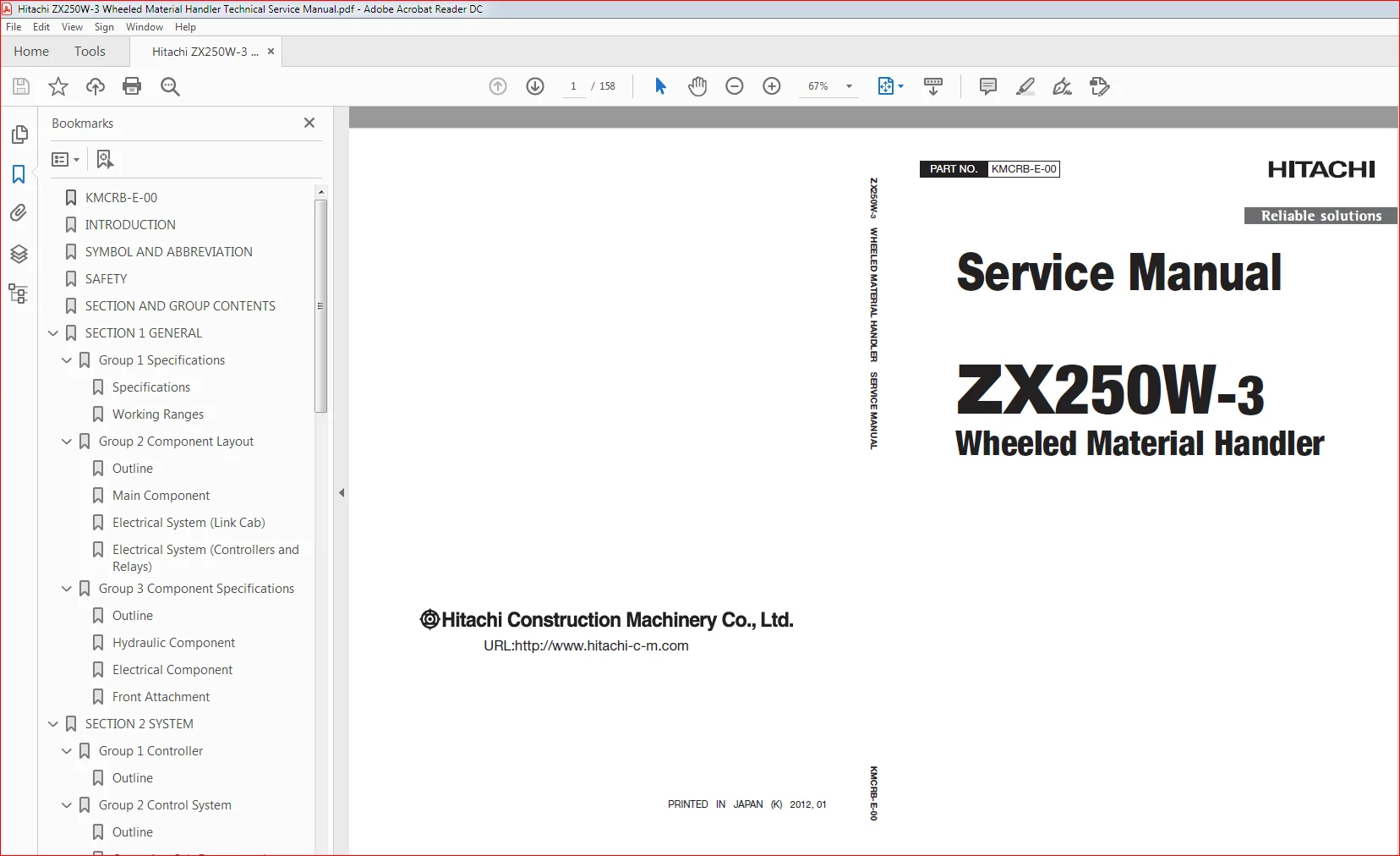
HITACHI ZX250W-3 WHEELED MATERIAL HANDLER TECHNICAL SERVICE MANUAL – PDF DOWNLOAD:
Image Preview:
Description:
Hitachi ZX250W-3 Wheeled Material Handler Technical Service Manual
To The Reader
This manual is written for an experienced technician to provide technical information needed to maintain and repair this machine.
Be sure to thoroughly read this manual for correct product information and service procedures
If you have any questions or comments, at if you found any errors regarding the contents of this manual, please contact using “Service Manual Revision Request Form” at the end of this manual.
Additional References
Please refer to the other materials (operator’s manual, parts catalog, engine technical material and Hitachi training material etc.) in addition to this manual.
Page Number
Each page has a number, located on the center lower part of the page, and each number contains the following information:
Example:
Technical Manual: T 1-3-5
T Technical Manual
1 Section Number
3 Group Number
5 Consecutive Page Number for Each Group
Table of Contents:
Hitachi ZX250W-3 Wheeled Material Handler Technical Service Manual
KMCRB-E-00.................................................  1
INTRODUCTION...............................................  3
SYMBOL AND ABBREVIATION....................................  5
SAFETY.....................................................  7
SECTION AND GROUP CONTENTS................................. 37
SECTION 1 GENERAL.......................................... 39
	Group 1 Specifications................................. 41
		Specifications..................................... 41
		Working Ranges..................................... 43
	Group 2 Component Layout............................... 45
		Outline............................................ 45
		Main Component..................................... 46
		Electrical System (Link Cab)....................... 48
		Electrical System (Controllers and Relays)......... 49
	Group 3 Component Specifications....................... 51
		Outline............................................ 51
		Hydraulic Component................................ 52
		Electrical Component............................... 53
		Front Attachment................................... 53
SECTION 2 SYSTEM........................................... 57
	Group 1 Controller..................................... 59
		Outline............................................ 59
	Group 2 Control System................................. 61
		Outline............................................ 61
		Operating Cab Emergency Lower Switch (External).... 66
	Group 3 ECM System..................................... 69
		Outline............................................ 69
	Group 4 Hydraulic System............................... 71
		Outline............................................ 71
		Pilot Circuit...................................... 72
		Main Circuit....................................... 84
	Group 5 Electrical System.............................. 91
		Outline............................................ 91
SECTION 3 COMPONENT OPERATION.............................. 95
	Group 1 Pump Device.................................... 97
		Outline............................................ 97
	Group 2 Swing Device................................... 99
		Outline............................................ 99
	Group 3 Control Valve..................................101
		Outline............................................101
		Pilot Circuit......................................102
SECTION 4 OPERATIONAL PERFORMANCE TEST.....................107
	Group 1 Introduction...................................109
		Operational Performance Tests......................109
		Preparation for Performance Tests..................110
	Group 2 Performance Standard...........................111
		Outline............................................111
		Performance Standard...............................112
		Sensor Activating Range............................116
	Group 3 Engine Performance Test........................117
		Outline............................................117
		Engine Speed.......................................118
	Group 4 Machine Performance Test.......................121
		Propeller Shaft Speed..............................121
		Brake Control Function.............................123
		Parking Brake Control Function.....................124
		Swing Speed........................................125
		Swing Bearing Play.................................126
		Hydraulic Cylinder Cycle Time......................128
		Hydraulic Cylinder Drift Check.....................130
		Control Lever Operating Force......................131
		Control Lever Stroke...............................132
	Group 5 Hydraulic Components Performance Test..........133
		Outline............................................133
		Primary Pilot Pressure.............................134
		Secondary Pilot Pressure...........................136
		Solenoid Valve Set Pressure........................138
		Relief Pressure....................................140
		Swing Motor Drainage...............................144
		Brake Pressure (Front and Rear)....................146
		Brake Accumulated Pressure.........................148
		Brake Warning Set Pressure (Decrease)..............150
		Brake Warning Set Pressure (Increase)..............152
SERVICE MANUAL REVISION REQUEST FORM.......................157
The Attached Diagram List..................................158
Please Note:
⦁ This is the SAME manual used by the dealers to troubleshoot any faults in your vehicle. This can be yours in 2 minutes after the payment is made.
⦁ Contact us at [email protected] should you have any queries before your purchase or that you need any other service / repair / parts operators manual.