Trusted Business
Verified & Licensed
Virus Free Files
100% Safe Downloads
Secure Payment
SSL Protected
Instant Delivery
Available Immediately
Sale!


Hitachi ZX290LC-5B ZX290LCN-5B Hydraulic Excavator Workshop Manual – PDF Download
Original price was: $71.95.$24.95Current price is: $24.95.
- Hitachi ZX290LC-5B ZX290LCN-5B Hydraulic Excavator Workshop Manual
- Part No:WDDA-EN-00
Instant PDF Download
Available immediately
Save to Your Device
Download & keep forever
Antivirus Scanned
100% virus-free
Trusted Worldwide
175,000+ customers
Description
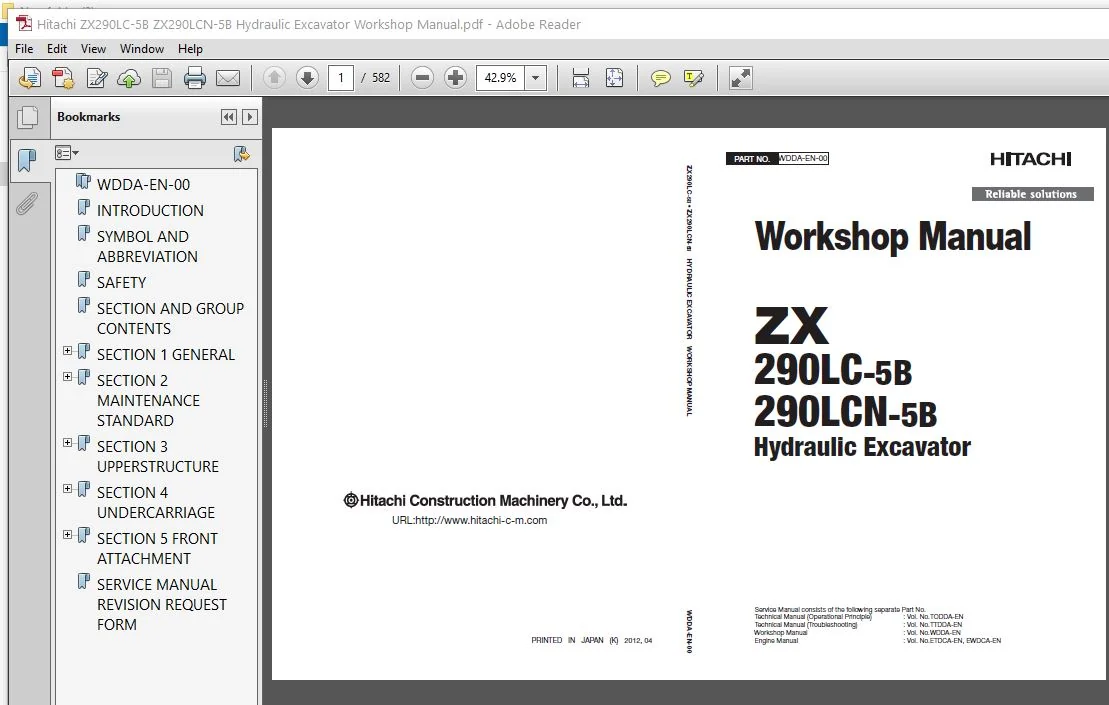
Hitachi ZX290LC-5B ZX290LCN-5B Hydraulic Excavator Workshop Manual
File Details:
Hitachi ZX290LC-5B ZX290LCN-5B Hydraulic Excavator Workshop Manual
- Manual Language:English
- Downloadable:Yes
- Pages: 582
- Size: 17.7 MB
- Format:PDF
HITACHI ZX290LC-5B ZX290LCN-5B HYDRAULIC EXCAVATOR WORKSHOP MANUAL – PDF DOWNLOAD:
Image Preview:
Description:
Hitachi ZX290LC-5B ZX290LCN-5B Hydraulic Excavator Workshop Manual
- To The Reader
This manual is written for an experienced technician to provide technical information needed to maintain and repair this machine.
Be sure to thoroughly read this manual for correct product information and service procedures
If you have any questions or comments, at if you found any errors regarding the contents of this manual, please contact using “Service Manual Revision Request Form” at the end of this manual. - Additional References
Please refer to the other materials (operator’s manual, parts catalog, engine technical material and Hitachi training material etc.) in addition to this manual. - Manual Composition
This manual consists the Technical Manual, the Workshop Manual and the Engine Manual.
Information included in the Technical Manual: Technical information needed for redelivery and delivery, operation and activation of all devices and systems, operational performance tests, and troubleshooting procedures.
Information included in the Workshop Manual: Technical information needed for maintenance and repair of the machine, tools and devices needed for maintenance and repair, maintenance standards, and removal / installation and assemble / disassemble procedures.
Information included in the Engine Manual: Technical information needed for redelivery and delivery and maintenance and repair of the machine, operation and activation of all devices and systems, troubleshooting and assemble / disassemble procedures.
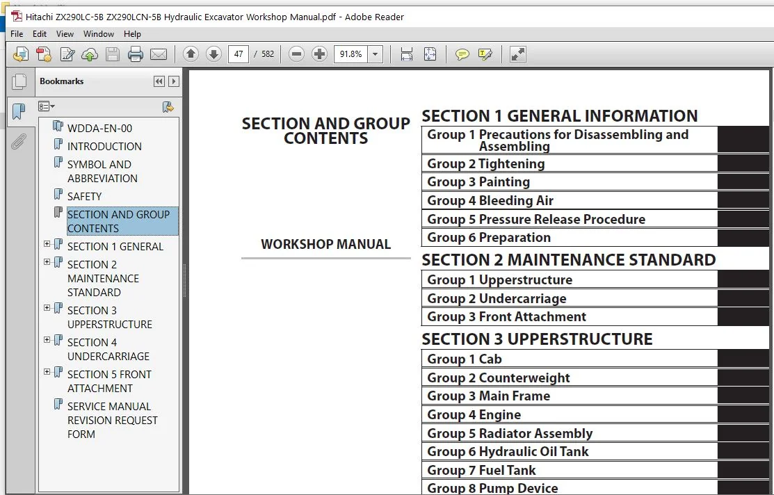
Table of Contents:
Hitachi ZX290LC-5B ZX290LCN-5B Hydraulic Excavator Workshop Manual
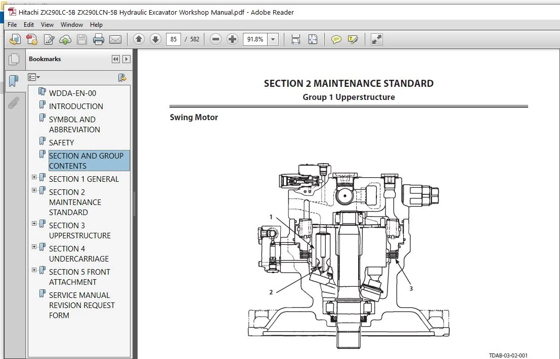
WDDA-EN-00.........................................................................  1
INTRODUCTION.......................................................................  3
SYMBOL AND ABBREVIATION............................................................  5
SAFETY.............................................................................  7
SECTION AND GROUP CONTENTS......................................................... 47
SECTION 1 GENERAL.................................................................. 49
	Group 1 Precautions for Disassembling and Assembling........................... 51
		Precautions for Disassembling and Assembling............................... 51
	Group 2 Tightening............................................................. 57
		Tightening Bolts and Nuts.................................................. 57
		Piping Joint............................................................... 60
	Group 3 Painting............................................................... 65
		Painting................................................................... 65
	Group 4 Bleeding Air........................................................... 67
		Bleeding Air from Hydraulic Oil Tank....................................... 67
		Bleeding Air from Hydraulic System......................................... 68
		Bleeding Air from Fuel System.............................................. 69
		Bleeding Air from Radiator................................................. 71
	Group 5 Pressure Release Procedure............................................. 73
		Hydraulic Circuit Pressure Release Procedure............................... 73
	Group 6 Preparation............................................................ 75
		Preparation before Inspection and Maintenance.............................. 75
SECTION 2 MAINTENANCE STANDARD..................................................... 79
	Group 1 Upperstructure......................................................... 81
		Pump Device................................................................ 81
		Swing Motor................................................................ 85
	Group 2 Undercarriage.......................................................... 89
		Travel Motor............................................................... 89
		Sprocket................................................................... 91
		Front Idler................................................................ 93
		Upper Roller............................................................... 95
		Lower Roller............................................................... 96
		Track...................................................................... 97
	Group 3 Front Attachment.......................................................101
		Pin and Bushing............................................................101
		Side Cutter (2021232, 2021233).............................................103
		Point (4512365)............................................................104
		Standard Dimensions for Arm and Bucket Connection..........................105
		Standard Dimensions for Arm and Boom Connection............................106
		Cylinder...................................................................107
SECTION 3 UPPERSTRUCTURE...........................................................111
	Group 1 Cab....................................................................113
		Removal and Installation of Cab............................................113
		Dimensions of Cab Glass....................................................129
	Group 2 Counterweight..........................................................149
		Removal and Installation of Counterweight..................................149
	Group 3 Main Frame.............................................................151
		Removal and Installation of Main Frame.....................................151
	Group 4 Engine.................................................................159
		Removal and Installation of Engine.........................................159
	Group 5 Radiator Assembly......................................................183
		Replacement of Radiator, Oil Cooler, and Intercooler.......................183
	Group 6 Hydraulic Oil Tank.....................................................197
		Removal and Installation of Hydraulic Oil Tank.............................197
	Group 7 Fuel Tank..............................................................205
		Removal and Installation of Fuel Tank......................................205
	Group 8 Pump Device............................................................215
		Removal and Installation of Pump Device....................................215
		Removal and Installation of Coupling.......................................225
		Disassembly of Pump Device.................................................229
		Assembly of Pump Device....................................................237
		Disassembly of Regulator...................................................249
		Assembly of Regulator......................................................251
		Disassembly of Solenoid Valve..............................................253
		Assembly of Solenoid Valve.................................................255
		Structure of Pilot Pump....................................................257
	Group 9 Control Valve..........................................................259
		Removal and Installation of Control Valve..................................259
		Disassembly of Housing.....................................................279
		Assembly of Housing........................................................281
		Disassembly of Control Valve (A Side)......................................283
		Assembly of Control Valve (A Side).........................................291
		Disassembly of Control Valve (B Side)......................................303
		Assembly of Control Valve (B Side).........................................312
	Group 10 Swing Device..........................................................325
		Removal and Installation of Swing Device...................................325
		Disassembly of Swing Device................................................329
		Assembly of Swing Device...................................................334
		Disassembly of Swing Motor.................................................341
		Assembly of Swing Motor....................................................344
		Structure of Swing Parking Brake Switch Valve..............................347
	Group 11 Pilot Valve...........................................................349
		Removal and Installation of Pilot Valve (Left).............................349
		Removal and Installation of Pilot Valve (Right)............................355
		Removal and Installation of Travel Pilot Valve.............................363
		Disassembly of Pilot Valves (Right and Left)...............................367
		Assembly of Pilot Valves (Right and Left)..................................370
		Disassembly of Travel Pilot Valve..........................................373
		Assembly of Travel Pilot Valve.............................................377
	Group 12 Solenoid Valve........................................................383
		Removal and Installation of Pilot Shut-Off Solenoid Valve..................383
		Removal and Installation of 5-Spool Solenoid Valve Unit....................387
		Removal and Installation of 2-Spool Solenoid Valve Unit....................391
		Disassembly of Pilot Shut-Off Solenoid Valve...............................395
		Assembly of Pilot Shut-Off Solenoid Valve..................................397
		Structure of 5-Spool Solenoid Valve Unit...................................399
		Structure of 2-Spool Solenoid Valve Unit...................................401
	Group 13 Signal Control Valve..................................................403
		Removal and Installation of Signal Control Valve...........................403
		Structure of Signal Control Valve..........................................409
	Group 14 Muffler Filter........................................................411
		Removal and Installation of Muffler Filter.................................411
		Disassembly of Muffler Filter..............................................423
		Assembly of Muffler Filter.................................................425
SECTION 4 UNDERCARRIAGE............................................................429
	Group 1 Swing Bearing..........................................................431
		Removal and Installation of Swing Bearing..................................431
		Disassembly of Swing Bearing...............................................435
		Assembly of Swing Bearing..................................................438
	Group 2 Travel Device..........................................................441
		Removal and Installation of Travel Device..................................441
		Disassembly of Travel Device...............................................445
		Assembly of Travel Device..................................................449
		Disassembly of Travel Motor................................................457
		Assembly of Travel Motor...................................................460
		Disassembly of Brake Valve.................................................465
		Assembly of Brake Valve....................................................467
		Precautions for Using Floating Seal........................................469
	Group 3 Center Joint...........................................................471
		Removal and Installation of Center Joint...................................471
		Disassembly of Center Joint................................................475
		Assembly of Center Joint...................................................477
		Replacement of Body and Spindle............................................480
	Group 4 Track Adjuster.........................................................481
		Removal and Installation of Track Adjuster.................................481
		Disassembly of Front Idler.................................................485
		Assembly of Front Idler....................................................488
		Disassembly of Track Adjuster..............................................491
		Assembly of Track Adjuster.................................................495
		Precautions for Using Floating Seal........................................499
	Group 5 Upper and Lower Rollers................................................501
		Removal and Installation of Upper Roller...................................501
		Removal and Installation of Lower Roller...................................505
		Disassembly of Lower Roller................................................511
		Assembly of Lower Roller...................................................513
		Precautions for Using Floating Seal........................................515
	Group 6 Track..................................................................517
		Removal and Installation of Track..........................................517
SECTION 5 FRONT ATTACHMENT.........................................................525
	Group 1 Front Attachment.......................................................527
		Removal and Installation of Front Attachment...............................527
	Group 2 Cylinder...............................................................535
		Removal and Installation of Boom Cylinder..................................535
		Removal and Installation of Arm Cylinder...................................539
		Removal and Installation of Bucket Cylinder................................543
		Removal and Installation of Positioning Cylinder...........................547
		Disassembly of Boom, Arm, Bucket Cylinders.................................551
		Assembly of Boom, Arm, Bucket Cylinders....................................555
		Disassembly of Positioning Cylinder........................................559
		Assembly of Positioning Cylinder...........................................562
	Group 3 Hose Rupture Valve.....................................................565
		Removal and Installation of Hose Rupture Valve for Boom Cylinder...........565
		Removal and Installation of Hose Rupture Valve for Arm Cylinder............567
		Removal and Installation of Hose Rupture Valve for Positioning Cylinder....569
		Structure of Hose Rupture Valve for Boom Cylinder (Right)..................571
		Structure of Hose Rupture Valve for Boom Cylinder (Left)...................573
		Structure of Hose Rupture Valve for Arm Cylinder...........................575
		Structure of Hose Rupture Valve for Positioning Cylinder...................577
SERVICE MANUAL REVISION REQUEST FORM...............................................581
Please Note:
⦁ This is the same manual used by the dealers to diagnose and troubleshoot your vehicle
⦁ You will be directed to the download page as soon as the purchase is completed. The whole payment and downloading process will take anywhere between 2-5 minutes
⦁ Need any other service / repair / parts manual, please feel free to contact [email protected] . We still have 50,000 manuals unlisted