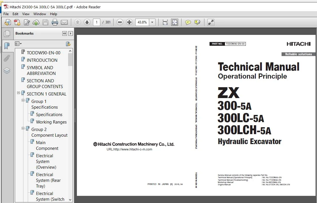
Hitachi ZX300-5A ZX300LC-5A ZX300LCH-5A Hydraulic Excavator Operational Principle Manual – PDF Download
Original price was: $89.95.$25.95Current price is: $25.95.
- Hitachi ZX300-5A ZX300LC-5A ZX300LCH-5A Hydraulic Excavator Operational Principle Manual
- Part No:TODDW90-EN-00
Description
Hitachi ZX300-5A ZX300LC-5A ZX300LCH-5A Hydraulic Excavator Operational Principle Manual
File Details:
Hitachi ZX300-5A ZX300LC-5A ZX300LCH-5A Hydraulic Excavator Operational Principle Manual
- Manual Language:English
- Pages: 700+
- Size:42.0 MB
- Format:PDF
- Downloadable:Yes
HITACHI ZX300-5A ZX300LC-5A ZX300LCH-5A HYDRAULIC EXCAVATOR OPERATIONAL PRINCIPLE MANUAL – PDF DOWNLOAD:
Image Preview:
Description:
Hitachi ZX300-5A ZX300LC-5A ZX300LCH-5A Hydraulic Excavator Operational Principle Manual
To The Reader
This manual is written for an experienced technician to provide technical information needed to maintain and repair this machine. The machine specification and description according to destination may be explained on this manual.
Be sure to thoroughly read this manual for correct product information and service procedures.
If you have any questions or comments, at if you found any errors regarding the contents of this manual, please contact using “Service Manual Revision Request Form” at the end of this manual.
Additional References
Please refer to the other materials (operator’s manual, parts catalog, engine technical material and Hitachi training material etc.) in addition to this manual.
Manual Composition
This manual consists the Technical Manual, the Workshop Manual and the Engine Manual.
Information included in the Technical Manual: Technical information needed for redelivery and delivery, operation and activation of all devices and systems, operational performance tests, and troubleshooting procedures.
Information included in the Workshop Manual: Technical information needed for maintenance and repair of the machine, tools and devices needed for maintenance and repair, maintenance standards, and removal / installation and assemble / disassemble procedures.
Information included in the Engine Manual: Technical information needed for redelivery and delivery and maintenance and repair of the machine, operation and activation of all devices and systems, troubleshooting and assemble / disassemble procedures.
Table Of Contents:
Hitachi ZX300-5A ZX300LC-5A ZX300LCH-5A Hydraulic Excavator Operational Principle Manual
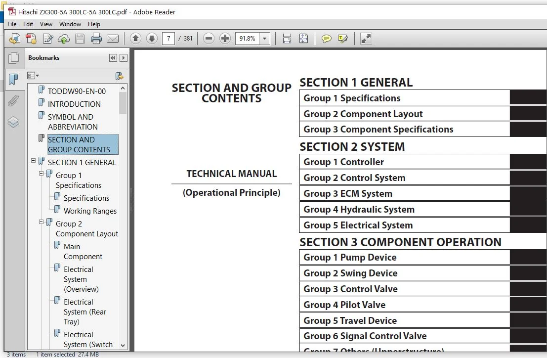
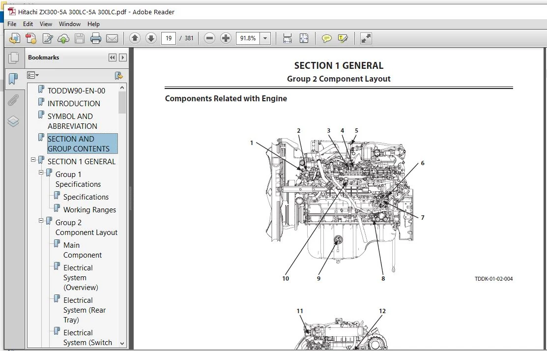
TODDW90-EN-00..............................................................................................................................................................  1
INTRODUCTION...............................................................................................................................................................  3
SYMBOL AND ABBREVIATION....................................................................................................................................................  5
SECTION AND GROUP CONTENTS.................................................................................................................................................  7
SECTION 1
GENERAL..........................................................................................................................................................  9
	Group 1 Specifications................................................................................................................................................. 11
		Specifications..................................................................................................................................................... 11
		Working Ranges..................................................................................................................................................... 12
	Group 2 Component Layout............................................................................................................................................... 13
		Main Component..................................................................................................................................................... 13
		Electrical System (Overview)....................................................................................................................................... 14
		Electrical System (Rear Tray)...................................................................................................................................... 15
		Electrical System (Switch Panel)................................................................................................................................... 16
		Electrical System (Around Air Cleaner)............................................................................................................................. 17
		Electrical System (Relays, etc.)................................................................................................................................... 18
		Components Related with Engine..................................................................................................................................... 19
		Components Related with Pump Device................................................................................................................................ 20
		Around Pump Device................................................................................................................................................. 21
		Components Related with Control Valve.............................................................................................................................. 22
		Components Related with Signal Control Valve....................................................................................................................... 22
		Components Related with Swing Device............................................................................................................................... 24
		Travel Device...................................................................................................................................................... 24
		3-Spool Solenoid Valve Unit........................................................................................................................................ 25
		Layout of Attachment Spec. Parts................................................................................................................................... 26
		Control Valve Side of Hydraulic Oil Tank........................................................................................................................... 28
	Group 3 Component Specifications....................................................................................................................................... 31
		Engine............................................................................................................................................................. 31
		Engine Accessories................................................................................................................................................. 35
		Hydraulic Component................................................................................................................................................ 36
		Electrical Component............................................................................................................................................... 40
SECTION 2
SYSTEM........................................................................................................................................................... 43
	Group 1 Controller..................................................................................................................................................... 45
		Outline............................................................................................................................................................ 45
		CAN Circuit........................................................................................................................................................ 46
	Group 2 Control System................................................................................................................................................. 49
		Outline............................................................................................................................................................ 49
		Engine Control..................................................................................................................................................... 52
		Pump Control....................................................................................................................................................... 84
		Valve Control (Standard)........................................................................................................................................... 96
		Valve Control (Option).............................................................................................................................................108
		Other Control......................................................................................................................................................118
	Group 3 ECM System.....................................................................................................................................................127
		Outline............................................................................................................................................................127
		Fuel Injection Control.............................................................................................................................................128
		Fuel Injection Amount Correction Control...........................................................................................................................136
		EGR Control........................................................................................................................................................138
		Preheating Control.................................................................................................................................................140
		Alarm Control......................................................................................................................................................141
	Group 4 Hydraulic System...............................................................................................................................................143
		Outline............................................................................................................................................................143
		Pilot Circuit......................................................................................................................................................144
		Main Circuit.......................................................................................................................................................154
		Breaker/Pulverizer/Crusher Circuit (Option)........................................................................................................................170
	Group 5 Electrical System..............................................................................................................................................181
		Outline............................................................................................................................................................181
		Main Circuit.......................................................................................................................................................182
		Electric Power Circuit (Key Switch: OFF)...........................................................................................................................184
		CAN Circuit........................................................................................................................................................186
		Accessory Circuit..................................................................................................................................................188
		Starting Circuit (Key Switch: START)...............................................................................................................................190
		Charging Circuit (Key Switch: ON)..................................................................................................................................192
		Surge Voltage Prevention Circuit...................................................................................................................................196
		Pilot Shut-Off Circuit (Key switch: ON)............................................................................................................................198
		Auto Shut-Down Circuit/Automatic Engine Stop Circuit at Low Temperature............................................................................................200
		Engine Stop Circuit................................................................................................................................................202
		Monitor Circuit....................................................................................................................................................205
		Security Circuit...................................................................................................................................................206
		Radio Circuit......................................................................................................................................................208
		Air Conditioner Circuit............................................................................................................................................208
		Accessory Circuit..................................................................................................................................................211
		Work Light Circuit.................................................................................................................................................212
		Wiper/Washer Circuit...............................................................................................................................................214
		Cab Light Circuit..................................................................................................................................................216
SECTION 3
COMPONENT OPERATION..............................................................................................................................................221
	Group 1 Pump Device....................................................................................................................................................223
		Outline............................................................................................................................................................223
		Main Pump..........................................................................................................................................................224
		Regulator..........................................................................................................................................................228
		Solenoid Valve.....................................................................................................................................................246
		Pilot Pump.........................................................................................................................................................248
		Pump Delivery Pressure Sensor......................................................................................................................................248
		Pump Control Pressure Sensor.......................................................................................................................................248
	Group 2 Swing Device...................................................................................................................................................249
		Outline............................................................................................................................................................249
		Swing Reduction Gear...............................................................................................................................................250
		Swing Motor........................................................................................................................................................251
		Swing Parking Brake................................................................................................................................................252
		Valve Unit.........................................................................................................................................................254
	Group 3 Control Valve..................................................................................................................................................257
		Outline............................................................................................................................................................257
		Hydraulic Circuit..................................................................................................................................................278
		Flow Combiner Valve................................................................................................................................................284
		Main Relief Valve..................................................................................................................................................286
		Overload Relief Valve (with Make-Up Function)......................................................................................................................290
		Regenerative Valve.................................................................................................................................................294
		Anti-Drift Valve...................................................................................................................................................298
		Flow Rate Control Valve............................................................................................................................................302
		Digging Regenerative Valve.........................................................................................................................................306
		Boom Lower Meter-In Cut Valve......................................................................................................................................308
		Auxiliary Flow Combiner Valve and Bypass Shut-Out Valve............................................................................................................310
	Group 4 Pilot Valve....................................................................................................................................................315
		Outline............................................................................................................................................................315
		Operation (Front Attachment/Swing and Travel Pilot Valves).........................................................................................................317
		Operation (Auxiliary Pilot Valve)..................................................................................................................................325
		Shockless Function (Only for Travel Pilot Valve)...................................................................................................................330
	Group 5 Travel Device..................................................................................................................................................331
		Outline............................................................................................................................................................331
		Travel Reduction Gear..............................................................................................................................................332
		Travel Motor.......................................................................................................................................................334
		Parking Brake......................................................................................................................................................336
		Travel Brake Valve.................................................................................................................................................338
		Overload Relief Valve..............................................................................................................................................342
		Travel Mode Control................................................................................................................................................344
	Group 6 Signal Control Valve...........................................................................................................................................349
		Outline............................................................................................................................................................349
		Pilot Port.........................................................................................................................................................350
		Shuttle Valve......................................................................................................................................................355
		Shockless Valve....................................................................................................................................................358
		Pump 1 and 2 Flow Rate Control Valve...............................................................................................................................362
		Bucket Flow Rate Control Valve Control Spool, Flow Combiner Valve Control Spool, Swing Parking Brake Release Spool, Arm 1 Flow Rate Control Valve Control Spool....364
	Group 7 Others (Upperstructure)........................................................................................................................................367
		Pilot Shut-Off Solenoid Valve......................................................................................................................................367
		Solenoid Valve.....................................................................................................................................................369
		Pilot Relief Valve.................................................................................................................................................373
		Recirculation Valve (Option).......................................................................................................................................374
	Group 8 Others (Undercarriage).........................................................................................................................................375
		Swing Bearing......................................................................................................................................................375
		Centerjoint........................................................................................................................................................376
		Track Adjuster (Front Idler Integrated Type).......................................................................................................................377
SERVICE MANUAL REVISION REQUEST FORM.......................................................................................................................................381
Please Note:
⦁ This is the SAME exact manual used by your dealers to fix your vehicle.
⦁ The same can be yours in the next 2-3 mins as you will be directed to the download page immediately after paying for the manual.
⦁ Any queries / doubts regarding your purchase, please feel free to contact [email protected]