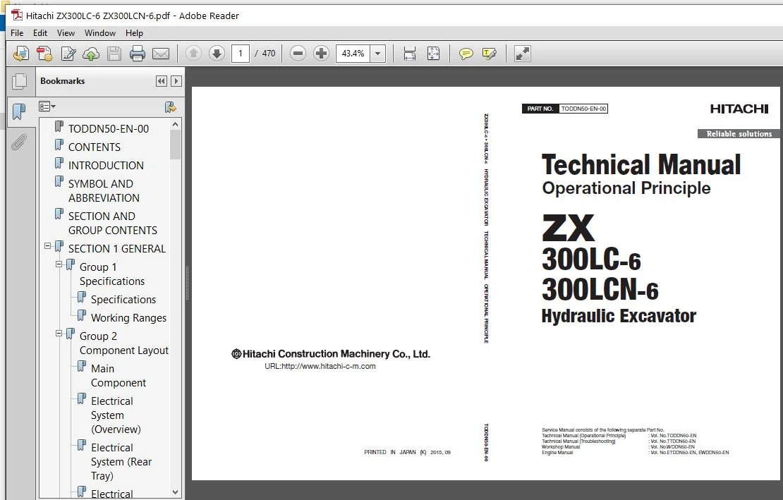
Hitachi ZX300LC-6 ZX300LCN-6 Hydraulic Excavator Operational Principle Technical Manual (TODDN50-EN-00) – PDF Download
Original price was: $75.95.$24.95Current price is: $24.95.
- Hitachi ZX300LC-6 ZX300LCN-6 Hydraulic Excavator Operational Principle Technical Manual
- Part No:TODDN50-EN-00
Description
Hitachi ZX300LC-6 ZX300LCN-6 Hydraulic Excavator Operational Principle Technical Manual (TODDN50-EN-00)
File Details:
Hitachi ZX300LC-6 ZX300LCN-6 Hydraulic Excavator Operational Principle Technical Manual (TODDN50-EN-00)
- Manual Language:English
- Pages: 470
- Size: 19.7 MB
- Format:PDF
- Downloadable:Yes
HITACHI ZX300LC-6 ZX300LCN-6 HYDRAULIC EXCAVATOR OPERATIONAL PRINCIPLE TECHNICAL MANUAL (TODDN50-EN-00) – PDF DOWNLOAD:
Image Preview:
Description:
Hitachi ZX300LC-6 ZX300LCN-6 Hydraulic Excavator Operational Principle Technical Manual (TODDN50-EN-00)
To The Reader
This manual is written for an experienced technician to provide technical information needed to maintain and repair this machine. The machine specification and description according to destination may be explained on this manual.
Be sure to thoroughly read this manual for correct product information and service procedures.
If you have any questions or comments, at if you found any errors regarding the contents of this manual, please contact using “Service Manual Revision Request Form” at the end of this manual.
Additional References
Please refer to the other materials (operator’s manual, parts catalog, engine technical material and Hitachi training material etc.) in addition to this manual.
Manual Composition
This manual consists the Technical Manual, the Workshop Manual and the Engine Manual.
Information included in the Technical Manual: Technical information needed for redelivery and delivery, operation and activation of all devices and systems, operational performance tests, and troubleshooting procedures.
Information included in the Workshop Manual: Technical information needed for maintenance and repair of the machine, tools and devices needed for maintenance and repair, maintenance standards, and removal / installation and assemble / disassemble procedures.
Information included in the Engine Manual: Technical information needed for redelivery and delivery and maintenance and repair of the machine, operation and activation of all devices and systems, troubleshooting and assemble / disassemble procedures.
Table Of Contents:
Hitachi ZX300LC-6 ZX300LCN-6 Hydraulic Excavator Operational Principle Technical Manual (TODDN50-EN-00)
TODDN50-EN-00.............................................................................................  1
CONTENTS..................................................................................................  3
INTRODUCTION..............................................................................................  9
SYMBOL AND ABBREVIATION................................................................................... 11
SECTION AND GROUP CONTENTS................................................................................ 13
SECTION 1 GENERAL......................................................................................... 15
	Group 1 Specifications................................................................................ 17
		Specifications.................................................................................... 17
		Working Ranges.................................................................................... 18
	Group 2 Component Layout.............................................................................. 19
		Main Component.................................................................................... 19
		Electrical System (Overview)...................................................................... 21
		Electrical System (Rear Tray)..................................................................... 22
		Electrical System (Switch Panel).................................................................. 23
		Electrical System (Utility Space)................................................................. 24
		Electrical System (Relays)........................................................................ 25
		Engine............................................................................................ 26
		Aftertreatment Device............................................................................. 27
		Pump Device....................................................................................... 28
		Around Pump Device................................................................................ 29
		Control Valve..................................................................................... 30
		Signal Control Valve.............................................................................. 30
		Swing Device...................................................................................... 32
		Travel Device..................................................................................... 32
		5-Spool Solenoid Valve Unit....................................................................... 33
		2-Spool Solenoid Valve Unit (AftertreatmentDevice Regeneration Control)........................... 33
		DEF Tank.......................................................................................... 34
		DEF Supply Module................................................................................. 34
		Layout of Attachment Spec. Parts.................................................................. 36
	Group 3 Component Specifications...................................................................... 41
		Engine............................................................................................ 41
		Engine Accessories................................................................................ 45
		Hydraulic Component............................................................................... 46
		Electrical Component.............................................................................. 50
SECTION 2 SYSTEM.......................................................................................... 53
	Group 1 Controller.................................................................................... 55
		Outline........................................................................................... 55
		CAN Circuit....................................................................................... 56
	Group 2 Control System................................................................................ 59
		Outline........................................................................................... 59
		Engine Control.................................................................................... 62
		Pump Control...................................................................................... 94
		Valve Control (Standard)..........................................................................118
		Valve Control (Optional)..........................................................................136
		Other Control.....................................................................................146
	Group 3 Engine System.................................................................................157
		ECM System........................................................................................157
		Fuel Injection Control............................................................................158
		Fuel Injection Amount Correction Control..........................................................166
		EGR Control.......................................................................................168
		Preheating Control................................................................................170
		Variable Turbocharger Control.....................................................................171
		Alarm Control.....................................................................................172
		Urea SCR System...................................................................................173
		Engine Output Restriction Control (INDUCEMENT)....................................................184
		Aftertreatment Device.............................................................................188
		Aftertreatment Device Regeneration Control........................................................190
	Group 4 Hydraulic System..............................................................................193
		Outline...........................................................................................193
		Pilot Circuit.....................................................................................194
		Main Circuit......................................................................................206
		Breaker/Pulverizer/Crusher Circuit (Optional).....................................................228
	Group 5 Electrical System.............................................................................239
		Outline...........................................................................................239
		Main Circuit......................................................................................240
		Electric Power Circuit (Key Switch: OFF)..........................................................242
		CAN Circuit.......................................................................................244
		Accessory Circuit (Key Switch: ACC)...............................................................246
		Starting Circuit (Key Switch: START)..............................................................248
		Charging Circuit (Key Switch: ON).................................................................250
		Surge Voltage Prevention Circuit..................................................................254
		Pilot Shut-Off Circuit (Key Switch: ON)...........................................................256
		Auto Shut-Down Circuit/Automatic Engine Stop Circuit at Low Temperature...........................258
		Engine Stop Circuit...............................................................................260
		Monitor Circuit...................................................................................263
		Security Circuit..................................................................................264
		Radio Circuit.....................................................................................266
		Air Conditioner Circuit...........................................................................266
		Accessory Circuit.................................................................................269
		Work Light Circuit................................................................................270
		Wiper/Washer Circuit..............................................................................272
		Wiper Circuit.....................................................................................272
		Cab Light Circuit.................................................................................274
SECTION 3 COMPONENT OPERATION.............................................................................279
	Group 1 Pump Device...................................................................................281
		Outline...........................................................................................281
		Main Pump.........................................................................................282
		Regulator.........................................................................................286
		Solenoid Valve....................................................................................310
		Pilot Pump........................................................................................312
		Pump Delivery Pressure Sensor.....................................................................312
		Pump Control Pressure Sensor......................................................................312
	Group 2 Swing Device..................................................................................313
		Outline...........................................................................................313
		Swing Reduction Gear..............................................................................314
		Swing Motor.......................................................................................315
		Swing Parking Brake...............................................................................316
		Valve Unit........................................................................................318
	Group 3 Control Valve.................................................................................331
		Outline...........................................................................................331
		Hydraulic Circuit.................................................................................354
		Flow Combiner Valve...............................................................................360
		Main Relief Valve.................................................................................362
		Overload Relief Valve (with Make-Up Function).....................................................366
		Regenerative Valve................................................................................370
		Anti-Drift Valve..................................................................................380
		Flow Rate Control Valve...........................................................................384
		Digging Regenerative Valve........................................................................388
		Boom Lower Meter-In Cut Valve.....................................................................390
		Auxiliary Flow Combiner Valve and Bypass Shut-Out Valve...........................................392
	Group 4 Pilot Valve...................................................................................397
		Outline...........................................................................................397
		Operation (Front Attachment/Swing and Travel Pilot Valves)........................................399
		Operation (Auxiliary, Positioning Pilot Valves)...................................................407
		Shockless Function (Only for Travel Pilot Valve)..................................................412
	Group 5 Travel Device.................................................................................413
		Outline...........................................................................................413
		Travel Reduction Gear.............................................................................414
		Travel Motor......................................................................................416
		Parking Brake.....................................................................................418
		Travel Brake Valve................................................................................420
		Overload Relief Valve.............................................................................424
		Travel Mode Control...............................................................................426
	Group 6 Signal Control Valve..........................................................................431
		Outline...........................................................................................431
		Pilot Port........................................................................................432
		Shuttle Valve.....................................................................................437
		Shockless Valve...................................................................................440
		Pump 1 Flow Rate Control Valve, Pump 2 Flow Rate Control Valve, Pump 3 Flow Rate Control Valve....444
		Flow Combiner Valve Control Spool, Swing Parking Brake Release Spool..............................446
	Group 7 Others (Upperstructure).......................................................................447
		Pilot Shut-Off Solenoid Valve.....................................................................447
		Solenoid Valve....................................................................................449
		Hose Rupture Valve................................................................................454
		Pilot Relief Valve................................................................................460
		Recirculation Valve ..............................................................................461
	Group 8 Others (Undercarriage)........................................................................463
		Swing Bearing.....................................................................................463
		Centerjoint.......................................................................................464
		Track Adjuster (Front Idler Integrated Type)......................................................465
SERVICE MANUAL REVISION REQUEST FORM......................................................................469
Please Note:
⦁ This is the SAME MANUAL used by the dealerships to diagnose your vehicle
⦁ No waiting for couriers / posts as this is a PDF manual and you can download it within 2 minutes time once you make the payment.
⦁ Your payment is all safe and the delivery of the manual is INSTANT – You will be taken to the DOWNLOAD PAGE.
⦁ So have no hesitations whatsoever and write to us about any queries you may have : heydownloadss @gmail.com