Hitachi ZX350LC-5B ZX350LCN-5B Hydraulic Excavator Technical Workshop Manual (WDDD-EN-00) – PDF Download
Original price was: $79.95.$24.95Current price is: $24.95.
- Hitachi ZX350LC-5B ZX350LCN-5B Hydraulic Excavator Technical Workshop Manual
- Part No:WDDD-EN-00
Description
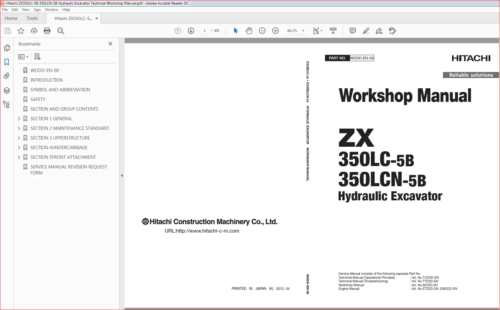
Hitachi ZX350LC-5B ZX350LCN-5B Hydraulic Excavator Technical Workshop Manual (WDDD-EN-00)
File Details:
Hitachi ZX350LC-5B ZX350LCN-5B Hydraulic Excavator Technical Workshop Manual (WDDD-EN-00)
- Manual Language:English
- Pages: 601
- Size: 15.3 MB
- Format:PDF
- Downloadable:Yes
HITACHI ZX350LC-5B ZX350LCN-5B HYDRAULIC EXCAVATOR TECHNICAL WORKSHOP MANUAL (WDDD-EN-00) – PDF DOWNLOAD:
Image Preview:
Description:
Hitachi ZX350LC-5B ZX350LCN-5B Hydraulic Excavator Technical Workshop Manual (WDDD-EN-00)
To The Reader
This manual is written for an experienced technician to provide technical information needed to maintain and repair this machine. The machine specification and description according to destination may be explained on this manual.
Be sure to thoroughly read this manual for correct product information and service procedures.
If you have any questions or comments, at if you found any errors regarding the contents of this manual, please contact using “Service Manual Revision Request Form” at the end of this manual.
Additional References
Please refer to the other materials (operator’s manual, parts catalog, engine technical material and Hitachi training material etc.) in addition to this manual.
Manual Composition
This manual consists the Technical Manual, the Workshop Manual and the Engine Manual.
Information included in the Technical Manual: Technical information needed for redelivery and delivery, operation and activation of all devices and systems, operational performance tests, and troubleshooting procedures.
Information included in the Workshop Manual: Technical information needed for maintenance and repair of the machine, tools and devices needed for maintenance and repair, maintenance standards, and removal / installation and assemble / disassemble procedures.
Information included in the Engine Manual: Technical information needed for redelivery and delivery and maintenance and repair of the machine, operation and activation of all devices and systems, troubleshooting and assemble / disassemble procedures.
Table Of Contents:
Hitachi ZX350LC-5B ZX350LCN-5B Hydraulic Excavator Technical Workshop Manual (WDDD-EN-00)
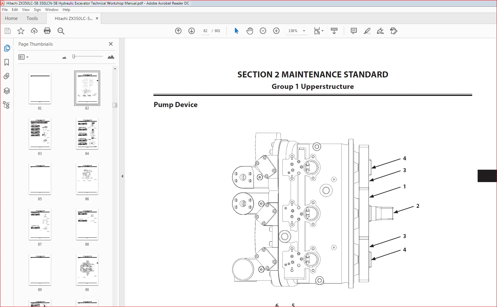
WDDD-EN-00........................................................................  1
INTRODUCTION......................................................................  2
SYMBOL AND ABBREVIATION...........................................................  4
SAFETY............................................................................  6
SECTION AND GROUP CONTENTS........................................................ 46
SECTION 1 GENERAL................................................................. 50
	Group 1 Precautions for Disassembling and Assembling.......................... 52
		Precautions for Disassembling andAssembling............................... 52
	Group 2 Tightening............................................................ 58
		Tightening Bolts and Nuts................................................. 58
		Piping Joint.............................................................. 61
	Group 3 Painting.............................................................. 66
		Painting.................................................................. 66
	Group 4 Bleeding Air.......................................................... 68
		Bleeding Air from Hydraulic Oil Tank...................................... 68
		Bleeding Air from Hydraulic System........................................ 69
		Bleeding Air from Fuel System............................................. 70
		Bleeding Air from Radiator................................................ 72
	Group 5 Pressure Release Procedure............................................ 74
		Hydraulic Circuit Pressure Release Procedure.............................. 74
	Group 6 Preparation........................................................... 76
		Preparation before Inspection andMaintenance.............................. 76
SECTION 2 MAINTENANCE STANDARD.................................................... 80
	Group 1 Upperstructure........................................................ 82
		Pump Device............................................................... 82
		Swing Motor............................................................... 86
	Group 2 Undercarriage......................................................... 90
		Travel Motor.............................................................. 90
		Sprocket
................................................................. 92
		Front Idler............................................................... 94
		Upper Roller.............................................................. 96
		Lower Roller.............................................................. 97
		Track..................................................................... 98
	Group 3 Front Attachment......................................................102
		Pin and Bushing...........................................................102
		Side Cutter...............................................................104
		Point.....................................................................104
		Side Cutter...............................................................105
		Point.....................................................................105
		Standard Dimensions for Arm and BucketConnection..........................106
		Standard Dimensions for Arm and BoomConnection............................107
		Cylinder..................................................................108
SECTION 3 UPPERSTRUCTURE..........................................................112
	Group 1 Cab...................................................................114
		Removal and Installation of Cab...........................................114
		Dimensions of Cab Glass...................................................130
	Group 2 Counterweight.........................................................150
		Removal and Installation of Counterweight.................................150
	Group 3 Main Frame............................................................152
		Removal and Installation of Main Frame....................................152
	Group 4 Engine................................................................160
		Removal and Installation of Engine........................................160
	Group 5 Radiator Assembly.....................................................184
		Replacement of Radiator and Intercooler...................................184
		Replacement of Oil Cooler.................................................196
	Group 6 Hydraulic Oil Tank....................................................202
		Removal and Installation of Hydraulic OilTank.............................202
	Group 7 Fuel Tank.............................................................210
		Removal and Installation of Fuel Tank.....................................210
	Group 8 Pump Device...........................................................218
		Removal and Installation of Pump Device...................................218
		Removal and Installation of Coupling......................................228
		Disassembly of Pump Device................................................230
		Assembly of Pump Device...................................................238
		Disassembly of Regulator..................................................250
		Assembly of Regulator.....................................................252
		Disassembly of Solenoid Valve.............................................254
		Assembly of Solenoid Valve................................................256
		Structure of Pilot Pump...................................................258
	Group 9 Control Valve.........................................................260
		Removal and Installation of Control Valve.................................260
		Disassembly of Housing....................................................280
		Assembly of Housing.......................................................282
		Disassembly of Control Valve (A Side).....................................284
		Assembly of Control Valve (A Side)........................................292
		Disassembly of Control Valve (B Side).....................................304
		Assembly of Control Valve (B Side)
.......................................313
	Group 10 Swing Device.........................................................326
		Removal and Installation of Swing Device..................................326
		Disassembly of Swing Device...............................................330
		Assembly of Swing Device..................................................336
		Disassembly of Swing Motor................................................342
		Assembly of Swing Motor...................................................345
		Structure of Swing Parking Brake SwitchValve..............................348
	Group 11 Pilot Valve..........................................................350
		Removal and Installation of Pilot Valve(Left).............................350
		Removal and Installation of Pilot Valve(Right)............................356
		Removal and Installation of Travel PilotValve.............................364
		Disassembly of Pilot Valves (Right and Left)..............................368
		Assembly of Pilot Valves (Right and Left).................................371
		Disassembly of Travel Pilot Valve.........................................374
		Assembly of Travel Pilot Valve............................................378
	Group 12 Solenoid Valve.......................................................384
		Removal and Installation of Pilot Shut-OffSolenoid Valve
.................384
		Removal and Installation of 5-Spool SolenoidValve Unit....................388
		Removal and Installation of 2-Spool SolenoidValve Unit....................392
		Disassembly of Pilot Shut-Off SolenoidValve...............................396
		Assembly of Pilot Shut-Off Solenoid Valve.................................398
		Structure of 5-Spool Solenoid Valve Unit..................................400
		Structure of 2-Spool Solenoid Valve Unit..................................402
	Group 13 Signal Control Valve.................................................404
		Removal and Installation of Signal ControlValve...........................404
		Structure of Signal Control Valve.........................................410
	Group 14 Muffler Filter.......................................................412
		Removal and Installation of Muffler Filter................................412
		Disassembly of Muffler Filter.............................................424
		Assembly of Muffler Filter................................................426
	Group 15 Fan Pump.............................................................428
		Removal and Installation of Fan Pump......................................428
		Structure of Fan Pump.....................................................432
	Group 16 Fan Valve............................................................434
		Removal and Installation of Fan Valve.....................................434
		Structure of Fan Valve....................................................436
		Structure of Solenoid Valve...............................................438
	Group 17 Fan Motor............................................................440
		Removal And Installation of Fan Motor.....................................440
		Structure of Fan Motor....................................................444
SECTION 4UNDERCARRIAGE............................................................448
	Group 1 Swing Bearing.........................................................450
		Removal and Installation of Swing Bearing.................................450
		Disassembly of Swing Bearing..............................................454
		Assembly of Swing Bearing.................................................457
	Group 2 Travel Device.........................................................460
		Removal and Installation of Travel Device.................................460
		Disassembly of Travel Device..............................................464
		Assembly of Travel Device.................................................468
		Disassembly of Travel Motor...............................................476
		Assembly of Travel Motor..................................................479
		Disassembly of Brake Valve................................................484
		Assembly of Brake Valve...................................................486
		Precautions for Using Floating Seal.......................................488
	Group 3 Center Joint..........................................................490
		Removal and Installation of Center Joint..................................490
		Disassembly of Center Joint...............................................494
		Assembly of Center Joint..................................................496
		Replacement of Body and Spindle...........................................499
	Group 4 Track Adjuster........................................................500
		Removal and Installation of Track Adjuster................................500
		Disassembly of Front Idler................................................504
		Assembly of Front Idler...................................................507
		Disassembly of Track Adjuster.............................................510
		Assembly of Track Adjuster................................................514
		Precautions for Using Floating Seal.......................................518
	Group 5 Upper and Lower Rollers...............................................520
		Removal and Installation of Upper Roller..................................520
		Removal and Installation of Lower Roller..................................524
		Disassembly of Lower Roller...............................................530
		Assembly of Lower Roller..................................................532
		Precautions for Using Floating Seal.......................................534
	Group 6 Track.................................................................536
		Removal and Installation of Track.........................................536
SECTION 5FRONT ATTACHMENT.........................................................544
	Group 1 Front Attachment......................................................546
		Removal and Installation of Front Attachment..............................546
	Group 2 Cylinder..............................................................554
		Removal and Installation of Boom Cylinder.................................554
		Removal and Installation of Arm Cylinder..................................558
		Removal and Installation of Bucket Cylinder...............................562
		Removal and Installation of PositioningCylinder...........................566
		Disassembly of Boom, Arm, and BucketCylinders.............................570
		Assembly of Boom, Arm, and BucketCylinders................................574
		Disassembly of Positioning Cylinder.......................................578
		Assembly of Positioning Cylinder..........................................581
	Group 3 Hose Rupture Valve....................................................584
		Removal and Installation of Hose RuptureValve for Boom Cylinder...........584
		Removal and Installation of Hose RuptureValve for Arm Cylinder............586
		Removal and Installation of Hose RuptureValve for Positioning Cylinder....588
		Structure of Hose Rupture Valve for BoomCylinder (Right)
.................590
		Structure of Hose Rupture Valve for BoomCylinder (Left)...................592
		Structure of Hose Rupture Valve for ArmCylinder...........................594
		Structure of Hose Rupture Valve forPositioning Cylinder...................596
SERVICE MANUAL REVISION REQUEST FORM..............................................600
Please Note:
⦁ This is the same manual used by the dealers to diagnose and troubleshoot your vehicle
⦁ You will be directed to the download page as soon as the purchase is completed. The whole payment and downloading process will take anywhere between 2-5 minutes
⦁ Need any other service / repair / parts manual, please feel free to contact [email protected] . We still have 50,000 manuals unlisted