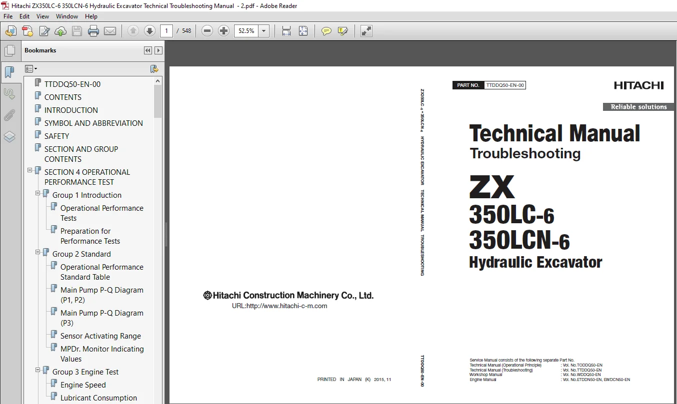
Hitachi ZX350LC-6 ZX350LCN-6 Hydraulic Excavator Technical Troubleshooting Manual (TTDDQ50-EN-00) – PDF Download
Original price was: $67.95.$26.95Current price is: $26.95.
- Hitachi ZX350LC-6 ZX350LCN-6 Hydraulic Excavator Technical Troubleshooting Manual
- Part No:TTDDQ50-EN-00
Description
Hitachi ZX350LC-6 ZX350LCN-6 Hydraulic Excavator Technical Troubleshooting Manual (TTDDQ50-EN-00)
File Details:
Hitachi ZX350LC-6 ZX350LCN-6 Hydraulic Excavator Technical Troubleshooting Manual (TTDDQ50-EN-00)
- Manual Language:English
- Pages: 548
- Size: 4.56 MB
- Format:PDF
- Downloadable:Yes
HITACHI ZX350LC-6 ZX350LCN-6 HYDRAULIC EXCAVATOR TECHNICAL TROUBLESHOOTING MANUAL (TTDDQ50-EN-00) – PDF DOWNLOAD:
Image Preview:
Description:
Hitachi ZX350LC-6 ZX350LCN-6 Hydraulic Excavator Technical Troubleshooting Manual (TTDDQ50-EN-00)
To The Reader
This manual is written for an experienced technician to provide technical information needed to maintain and repair this machine. The machine specification and description according to destination may be explained on this manual.
Be sure to thoroughly read this manual for correct product information and service procedures.
If you have any questions or comments, at if you found any errors regarding the contents of this manual, please contact using “Service Manual Revision Request Form” at the end of this manual.
Additional References
Please refer to the other materials (operator’s manual, parts catalog, engine technical material and Hitachi training material etc.) in addition to this manual.
Manual Composition
This manual consists the Technical Manual, the Workshop Manual and the Engine Manual.
Information included in the Technical Manual: Technical information needed for redelivery and delivery, operation and activation of all devices and systems, operational performance tests, and troubleshooting procedures.
Information included in the Workshop Manual: Technical information needed for maintenance and repair of the machine, tools and devices needed for maintenance and repair, maintenance standards, and removal / installation and assemble / disassemble procedures.
Information included in the Engine Manual: Technical information needed for redelivery and delivery and maintenance and repair of the machine, operation and activation of all devices and systems, troubleshooting and assemble / disassemble procedures.
Table Of Contents:
Hitachi ZX350LC-6 ZX350LCN-6 Hydraulic Excavator Technical Troubleshooting Manual (TTDDQ50-EN-00)
TTDDQ50-EN-00.............................................................................................  1
CONTENTS..................................................................................................  3
INTRODUCTION..............................................................................................  7
SYMBOL AND ABBREVIATION...................................................................................  9
SAFETY.................................................................................................... 11
SECTION AND GROUP CONTENTS................................................................................ 53
SECTION 4
OPERATIONAL PERFORMANCE TEST.................................................................... 55
	Group 1 Introduction.................................................................................. 57
		Operational Performance Tests..................................................................... 57
		Preparation for Performance Tests................................................................. 58
	Group 2 Standard...................................................................................... 59
		Operational Performance Standard Table............................................................ 59
		Main Pump P-Q Diagram (P1, P2).................................................................... 69
		Main Pump P-Q Diagram (P3)........................................................................ 70
		Sensor Activating Range........................................................................... 72
		MPDr. Monitor Indicating Values................................................................... 74
	Group 3 Engine Test................................................................................... 87
		Engine Speed...................................................................................... 87
		Lubricant Consumption............................................................................. 90
	Group 4 Machine Performance Test...................................................................... 91
		Travel Speed...................................................................................... 91
		Track Revolution Speed............................................................................ 92
		Mistrack Check.................................................................................... 93
		Travel Parking Leakage............................................................................ 94
		Swing Speed....................................................................................... 95
		Swing Function Drift Check........................................................................ 96
		Swing Motor Leakage............................................................................... 98
		Maximum Swingable Slant Angle.....................................................................100
		Swing Bearing Play................................................................................102
		Hydraulic Cylinder Cycle Time.....................................................................104
		Dig Function Drift Check..........................................................................106
		Control Lever Operating Force.....................................................................109
		Control Lever Stroke..............................................................................110
		Combined Operation of Boom Raise and Swing Function Check.........................................111
		Combined Operation of Boom Raise and Arm Roll-In Function Check...................................112
		Clearance of Front Attachment Connecting Part.....................................................113
	Group 5 Component Test................................................................................115
		Primary Pilot Pressure............................................................................115
		Secondary Pilot Pressure..........................................................................117
		5-Spool Solenoid Valve Set Pressure...............................................................118
		2-Spool Solenoid Valve (Aftertreatment Device Regeneration Control) Set Pressure..................119
		Main Pump Delivery Pressure.......................................................................121
		Main Relief Set Pressure..........................................................................122
		Relief pressure (when relieving swing)............................................................126
		Overload Relief Valve Set Pressure................................................................128
		Main Pump Flow Rate Measurement...................................................................130
		Swing Motor Drainage..............................................................................140
		Travel Motor Drainage.............................................................................142
	Group 6 Adjustment....................................................................................145
		Rewrite of Aftertreatment Device Serial No........................................................145
		How to Clear Fault Code...........................................................................146
		Procedure after Replacing DCU and ECM.............................................................147
		Air Bleeding from the Diesel Exhaust Fluid Defrosting Piping......................................148
		How to Check Manual Regeneration Switch...........................................................149
		Remedy at DEF Pressure Decrease...................................................................150
		Remedy at DEF Abnormal Quality....................................................................152
		Clean DEF Tank....................................................................................154
		Remedy when Mixing Oil in DEF Tank................................................................155
SECTION 5
TROUBLESHOOTING.................................................................................159
	Group 1 Diagnosing Procedure..........................................................................161
		Introduction......................................................................................161
		Diagnosis Procedure...............................................................................162
		Electrical System Inspection......................................................................165
		Precautions for Inspection and Maintenance........................................................166
		Instructions for Disconnecting Connectors.........................................................168
		Fuse Inspection...................................................................................170
		Fusible Link Inspection...........................................................................173
		Battery Voltage Check.............................................................................174
		Alternator Check..................................................................................175
		Continuity Check..................................................................................176
		Voltage and Current Measurement...................................................................178
		Check by False Signal.............................................................................185
		Test Wire Harness.................................................................................186
	Group 2 Monitor.......................................................................................189
		Outline...........................................................................................189
		Operating Procedures of Service Menu..............................................................190
		Setting Menu......................................................................................231
		Inspection of Engine Oil Level, Coolant Level, Hour Meter, and Fuel Gauge.........................236
		Fuel Gauge, Coolant Temperature Gauge, DEF/AdBlue Gauge...........................................237
	Group 3 e-Service.....................................................................................239
		Outline...........................................................................................239
		List of Operation Data............................................................................240
		Communication System..............................................................................242
	Group 4 Component Layout..............................................................................243
		Main Component....................................................................................243
		Electrical System (Overview)......................................................................245
		Electrical System (Rear Tray).....................................................................246
		Electrical System (Switch Panel)..................................................................247
		Electrical System (Utility Space).................................................................248
		Electrical System (Relays)........................................................................249
		Engine............................................................................................250
		After treatment Device............................................................................251
		Pump Device.......................................................................................252
		Around Pump Device................................................................................253
		Control Valve.....................................................................................254
		Signal Control Valve..............................................................................254
		Swing Device......................................................................................256
		Travel Device.....................................................................................256
		5-Spool Solenoid Valve Unit.......................................................................257
		2-Spool Solenoid Valve Unit (After treatment Device Regeneration Control).........................257
		DEF Tank..........................................................................................258
		DEF Supply Module.................................................................................258
		Layout of Attachment Spec. Parts..................................................................260
		Components in Control Valve.......................................................................266
		Pilot Port........................................................................................288
		Port Layout of Control Valve (Main Circuit).......................................................292
		Port Layout of Control Valve (Pilot Circuit)......................................................294
	Group 5 Troubleshooting A.............................................................................297
		Troubleshooting A (Base Machine Diagnosis By Using Fault Codes) Procedure.........................297
		MC Fault Code List................................................................................299
		ECM Fault Code List...............................................................................320
		DCU Fault Code List...............................................................................334
		Monitor Controller (Monitor) Fault Code List......................................................341
		Monitor Controller (Information) Fault Code List..................................................342
		Air Conditioner Controller Fault Code List........................................................345
		Communication Terminal Fault Code List............................................................346
		MC Fault Codes 11000 to 11002.....................................................................347
		MC Fault Code 11003...............................................................................348
		MC Fault Codes 11006, 11007,11009
Monitor Controller (Monitor) Fault Codes 13002, 13003, 13005....351
		CAN0 Harness Check................................................................................352
		ISO-CAN (Engine) Harness Check....................................................................356
		MC Fault Codes 11008, 11010
Monitor Controller (Monitor) Fault Codes 13004, 13006, 13007..........359
		CAN1 Harness Check................................................................................360
		MC Fault Code 11100...............................................................................363
		MC Fault Code 11101...............................................................................364
		MC Fault Codes 11200 to 11202.....................................................................365
		MC Fault Code 11203...............................................................................366
		MC Fault Codes 11206 to 11208.....................................................................367
		MC Fault Codes 11301 to 11303.....................................................................368
		MC Fault Codes 11304, 11307, 11325................................................................369
		MC Fault Codes 11995, 11997.......................................................................370
		MC Fault Code 11400...............................................................................371
		MC Fault Code 11401...............................................................................372
		MC Fault Code 11402...............................................................................373
		MC Fault Code 11403...............................................................................374
		MC Fault Code 11406...............................................................................375
		MC Fault Code 11407...............................................................................376
		MC Fault Code 11408...............................................................................377
		MC Fault Code 11409...............................................................................378
		MC Fault Code 11410...............................................................................379
		MC Fault Code 11411...............................................................................380
		MC Fault Codes 11434, 11435.......................................................................381
		MC Fault Code 11436...............................................................................382
		MC Fault Codes 11458, 11459.......................................................................383
		MC Fault Code 11412...............................................................................384
		MC Fault Code 11427...............................................................................385
		MC Fault Code 11428...............................................................................386
		MC Fault Code 11901...............................................................................387
		MC Fault Codes 20009, 20013, 20062................................................................388
		MC Fault Codes 20010 to 20012.....................................................................389
		Monitor Controller (Information) Fault Codes 13304, 13310.........................................390
		Monitor Controller (Information) Fault Code 13311.................................................391
		Monitor Controller (Information) Fault Codes 20100 to 20114.......................................392
		Monitor Controller (Information) Fault Codes 20109 to 20149.......................................393
		Air Conditioner Controller Fault Codes 11 to 22...................................................394
		Air Conditioner Controller Fault Codes 43 to 92...................................................395
	Group 6 Troubleshooting B.............................................................................397
		Troubleshooting B (Machine Diagnosis by Using Trouble Symptom) Procedure..........................397
		Relationship between Machine Trouble Symptoms and Related Parts...................................399
		Correlation between Trouble Symptoms and Part Failures............................................426
		Engine System Troubleshooting.....................................................................446
		All Actuator System Troubleshooting...............................................................456
		Front Attachment System Troubleshooting...........................................................466
		Swing System Troubleshooting......................................................................482
		Travel System Troubleshooting.....................................................................484
		Other System Troubleshooting......................................................................490
		Exchange Inspection...............................................................................495
		How to Lowering Boom When Emergency and When Engine Stops without Hose Rupture Valve..............498
		How to Lowering Boom When Emergency and When Engine Stops with Hose Rupture Valve.................499
		Attachment Circuit Pressure Release Procedure.....................................................500
	Group 7 Air Conditioner...............................................................................501
		Outline...........................................................................................501
		Functions of Main Parts...........................................................................504
		Troubleshooting...................................................................................509
		Air Conditioner Controller Fault Code List........................................................510
		Air Conditioner Controller Fault Codes 11 to 22...................................................511
		Air Conditioner Controller Fault Codes 43 to 92...................................................512
		Work after Replacing Components...................................................................534
		Refill Compressor Oil.............................................................................535
		Charge Air Conditioner with Refrigerant...........................................................536
		Hose and Pipe Tightening Torque...................................................................544
SERVICE MANUAL REVISION REQUEST FORM......................................................................547
The Attached Diagram List.................................................................................548
Please Note:
⦁ This is the SAME exact manual used by your dealers to fix your vehicle.
⦁ The same can be yours in the next 2-3 mins as you will be directed to the download page immediately after paying for the manual.
⦁ Any queries / doubts regarding your purchase, please feel free to contact [email protected]