Hitachi ZX400R-3 ZX400LCH-3 Hydraulic Excavator Technical Operational Principle Manual (TO1JK-E-00) – PDF Download
Original price was: $67.95.$23.95Current price is: $23.95.
- Hitachi ZX400R-3 ZX400LCH-3 Hydraulic Excavator Technical Operational Principle Manual
- Part No:TO1JK-E-00
Description
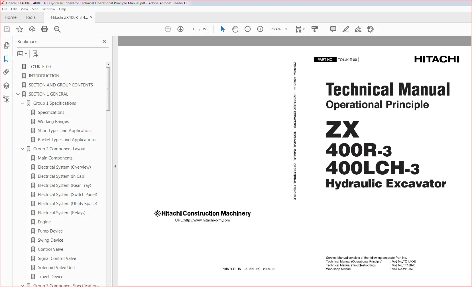
Hitachi ZX400R-3 ZX400LCH-3 Hydraulic Excavator Technical Operational Principle Manual (TO1JK-E-00)
File Details:
Hitachi ZX400R-3 ZX400LCH-3 Hydraulic Excavator Technical Operational Principle Manual (TO1JK-E-00)
- Manual Language:English
- Pages: 353
- Size: 8.26 MB
- Format:PDF
- Downloadable:Yes
HITACHI ZX400R-3 ZX400LCH-3 HYDRAULIC EXCAVATOR TECHNICAL OPERATIONAL PRINCIPLE MANUAL (TO1JK-E-00) – PDF DOWNLOAD:
Description:
Hitachi ZX400R-3 ZX400LCH-3 Hydraulic Excavator Technical Operational Principle Manual (TO1JK-E-00)
TO THE READER
• This manual is written for an experienced technician to provide technical information needed to maintain and repair this machine.
• Be sure to thoroughly read this manual for correct product information and service procedures.
• If you have any questions or comments, at if you found any errors regarding the contents of this manual, please contact using “Service Manual Revision Request Form” at the end of this manual.
ADDITIONAL REFERENCES
• Please refer to the other materials (operator’s manual, parts catalog, engine technical material and Hitachi training material etc.) in addition to this manual.
MANUAL COMPOSITION
• This manual consists the Technical Manual and the Workshop Manual.
• Information included in the Technical Manual: technical information needed for redelivery and delivery, operation and activation of all devices and systems, operational performance tests, and troubleshooting procedures.
• Information included in the Workshop Manual: technical information needed for maintenance and repair of the machine, tools and devices needed for maintenance and repair, maintenance standards, and removal/installation and assemble/ disassemble procedures.
Table Of Contents:
Hitachi ZX400R-3 ZX400LCH-3 Hydraulic Excavator Technical Operational Principle Manual (TO1JK-E-00)
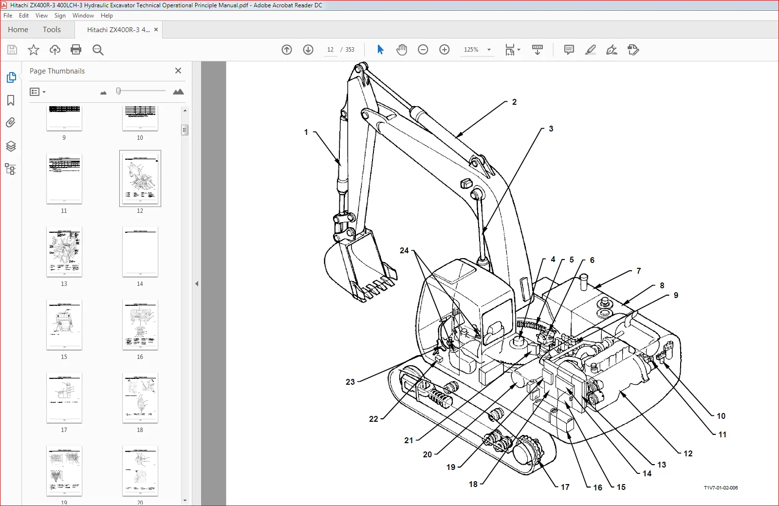
TO1JK-E-00................................................................................................................................................................  1
INTRODUCTION..............................................................................................................................................................  3
SECTION AND GROUP CONTENTS................................................................................................................................................  5
SECTION 1 GENERAL.........................................................................................................................................................  6
	Group 1 Specifications................................................................................................................................................  8
		Specifications....................................................................................................................................................  8
		Working Ranges....................................................................................................................................................  9
		Shoe Types and Applications....................................................................................................................................... 10
		Bucket Types and Applications..................................................................................................................................... 11
	Group 2 Component Layout.............................................................................................................................................. 12
		Main Components................................................................................................................................................... 12
		Electrical System (Overview)...................................................................................................................................... 13
		Electrical System (In Cab)........................................................................................................................................ 15
		Electrical System (Rear Tray)..................................................................................................................................... 16
		Electrical System (Switch Panel).................................................................................................................................. 17
		Electrical System (Utility Space)................................................................................................................................. 18
		Electrical System (Relays)........................................................................................................................................ 18
		Engine............................................................................................................................................................ 19
		Pump Device....................................................................................................................................................... 20
		Swing Device...................................................................................................................................................... 20
		Control Valve..................................................................................................................................................... 21
		Signal Control Valve.............................................................................................................................................. 21
		Solenoid Valve Unit............................................................................................................................................... 22
		Travel Device..................................................................................................................................................... 22
	Group 3 Component Specifications...................................................................................................................................... 24
		Engine............................................................................................................................................................ 24
		Engine Accessories................................................................................................................................................ 27
		Hydraulic Component............................................................................................................................................... 28
		Electrical Component.............................................................................................................................................. 33
SECTION 2 SYSTEM.......................................................................................................................................................... 36
	Group 1 Controller.................................................................................................................................................... 38
		Outline........................................................................................................................................................... 38
		Can (Network Provided for Machine)................................................................................................................................ 39
		MC: Main Controller............................................................................................................................................... 41
		ECM: Engine Control Module........................................................................................................................................ 57
		ICF: Information Controller....................................................................................................................................... 59
		Monotor Unit...................................................................................................................................................... 62
	Group 2 Control System................................................................................................................................................ 72
		Outline........................................................................................................................................................... 72
		Engine Control.................................................................................................................................................... 75
		Pump Control...................................................................................................................................................... 97
		Valve Control.....................................................................................................................................................111
		Other Controls....................................................................................................................................................131
	Group 3 ECM System....................................................................................................................................................136
		Outline...........................................................................................................................................................136
		Fuel Injection Control............................................................................................................................................137
		Engine Start Control..............................................................................................................................................145
		EGR (Exhaust Gas Recirculation) Control...........................................................................................................................147
		Fuel Injection Amount Correction..................................................................................................................................149
		Fuel Filter Restriction Indicator Control.........................................................................................................................150
		Engine Stop Control...............................................................................................................................................151
	Group 4 Hydraulic System..............................................................................................................................................154
		Outline...........................................................................................................................................................154
		Pilot Circuit.....................................................................................................................................................155
		Main Circuit......................................................................................................................................................165
		Boom Lower Meter-In Cut Control...................................................................................................................................175
	Group 5 Electrical System.............................................................................................................................................180
		Outline...........................................................................................................................................................180
		Main Circuit......................................................................................................................................................181
		Electric Power Circuit (Key Switch: OFF)..........................................................................................................................183
		Accessory Circuit.................................................................................................................................................185
		Starting Circuit (Key Switch: START)..............................................................................................................................187
		Charging Circuit (Key Switch: ON).................................................................................................................................189
		Serge Voltage Prevention Circuit..................................................................................................................................193
		Pilot Shut-Off Circuit (Key Switch: ON)...........................................................................................................................195
		Security Lock Circuit.............................................................................................................................................197
		Engine Stop Circuit (Key Switch: OFF).............................................................................................................................199
		Security Horn Circuit.............................................................................................................................................201
		Working Light Circuit.............................................................................................................................................203
		Wiper Circuit.....................................................................................................................................................205
SECTION 3 COMPONENT OPERATION.............................................................................................................................................210
	Group 1 Pump Device...................................................................................................................................................212
		Outline...........................................................................................................................................................212
		Main Pump 1, 2....................................................................................................................................................213
		Regulator.........................................................................................................................................................217
		Pilot Pump........................................................................................................................................................233
		Pump Delivery Pressure Sensor.....................................................................................................................................233
	Group 2 Swing Device..................................................................................................................................................234
		Outline...........................................................................................................................................................234
		Swing Reduction Gear..............................................................................................................................................235
		Swing Motor.......................................................................................................................................................236
		Swing Parking Brake...............................................................................................................................................237
		Valve Unit........................................................................................................................................................239
		Swing Dampener Valve..............................................................................................................................................242
	Group 3 Control Valve.................................................................................................................................................252
		Outline...........................................................................................................................................................252
		Hydraulic Circuit.................................................................................................................................................267
		Flow Combiner Valve...............................................................................................................................................273
		Main Relief Valve.................................................................................................................................................275
		Overload Relief Valve.............................................................................................................................................277
		Regenerative Valve................................................................................................................................................279
		Anti-Drift Valve..................................................................................................................................................283
		Flow Rate Control Valve...........................................................................................................................................285
		Digging Regenerative Valve........................................................................................................................................287
		Boom Lower Meter-In Cut Valve.....................................................................................................................................289
		Bypass Shut-Out Valve.............................................................................................................................................291
	Group 4 Pilot Valve...................................................................................................................................................292
		Outline...........................................................................................................................................................292
		Operation.........................................................................................................................................................295
		Shockless Function(Only for Travel Pilot Valve)...................................................................................................................303
	Group 5 Travel Device.................................................................................................................................................304
		Outline...........................................................................................................................................................304
		Travel Reduction Gear.............................................................................................................................................305
		Travel Motor......................................................................................................................................................306
		Travel Brake Valve................................................................................................................................................308
		Parking Brake.....................................................................................................................................................315
	Group 6 Signal Control Valve..........................................................................................................................................318
		Outline...........................................................................................................................................................318
		Pilot Port........................................................................................................................................................319
		Shuttle Valve.....................................................................................................................................................323
		Shockless Valve...................................................................................................................................................327
		Pump 1 and Pump 2 Flow Rate Control Valves........................................................................................................................331
		Bucket Flow Rate Control ValveControl Spool, Flow Combiner Valve Control Spool, Swing Parking Brake Release Spool, Arm 1 Flow Rate Control Valve Control Spool....333
	Group 7 Others (Upperstructure).......................................................................................................................................334
		Pilot Shut-Off Solenoid Valve.....................................................................................................................................334
		Solenoid Valve....................................................................................................................................................336
		Hose Rupture Valve................................................................................................................................................339
		Pilot Relief Valve................................................................................................................................................345
	Group 8 Others (Undercarriage)........................................................................................................................................346
		Swing Bearing.....................................................................................................................................................346
		Center Joint......................................................................................................................................................347
		Track Adjuster....................................................................................................................................................348
SERVICE MANUAL REVISION REQUEST FORM......................................................................................................................................352
Please Note:
⦁ This is the SAME manual used by the dealers to troubleshoot any faults in your vehicle. This can be yours in 2 minutes after the payment is made.
⦁ Contact us at [email protected] should you have any queries before your purchase or that you need any other service / repair / parts operators manual.