Hitachi ZX470-5B ZX470LC-5B ZX470H-5B ZX470LCH-5B ZX470R-5B ZX470LCR-5B ZX520LCH-5B Hydraulic Excavator Technical Operational Principle Manual (TOJAA-EN-01) – PDF Download
Original price was: $87.95.$24.95Current price is: $24.95.
- Hitachi ZX470-5B ZX470LC-5B ZX470H-5B ZX470LCH-5B ZX470R-5B ZX470LCR-5B ZX520LCH-5B Hydraulic Excavator Technical Operational Principle Manual
- Part No:TOJAA-EN-01
Description
Hitachi ZX470-5B ZX470LC-5B ZX470H-5B ZX470LCH-5B ZX470R-5B ZX470LCR-5B ZX520LCH-5B Hydraulic Excavator Technical Operational Principle Manual (TOJAA-EN-01)
File Details:
Hitachi ZX470-5B ZX470LC-5B ZX470H-5B ZX470LCH-5B ZX470R-5B ZX470LCR-5B ZX520LCH-5B Hydraulic Excavator Technical Operational Principle Manual (TOJAA-EN-01)
- Manual Language:English
- Pages: 440
- Size: 8.63 MB
- Format:PDF
- Downloadable:Yes
HITACHI ZX470-5B ZX470LC-5B ZX470H-5B ZX470LCH-5B ZX470R-5B ZX470LCR-5B ZX520LCH-5B HYDRAULIC EXCAVATOR TECHNICAL OPERATIONAL PRINCIPLE MANUAL (TOJAA-EN-01) – PDF DOWNLOAD:
Image Preview:
Description:
Hitachi ZX470-5B ZX470LC-5B ZX470H-5B ZX470LCH-5B ZX470R-5B ZX470LCR-5B ZX520LCH-5B Hydraulic Excavator Technical Operational Principle Manual (TOJAA-EN-01)
TO THE READER
• This manual is written for an experienced technician to provide technical information needed to maintain and repair this machine.
• Be sure to thoroughly read this manual for correct product information and service procedures.
• If you have any questions or comments, at if you found any errors regarding the contents of this manual, please contact using “Service Manual Revision Request Form at the end of this manual.
ADDITIONAL REFERENCES
• Please refer to the materials listed below in addition to this manual.
• The Operator’s Manual
• The Parts Catalog
• Operation Manual of the Engine
• Parts Catalog of the Engine
• Hitachi Training Material
MANUAL COMPOSITION
• This manual consists of three portions: the Technical Manual (Operational Principle), the Technical Manual (Troubleshooting) and the Workshop Manual.
• Information included in the Technical Manual (Operational Principle): technical information needed for redeliver and delivery, operation and activation of all devices and systems.
• Information included in the Technical Manual (Troubleshooting): technical information needed for operational performance tests, and troubleshooting procedures.
• Information included in the Workshop Manual: technical information needed for maintenance and repair of the machine, tools and devices needed for maintenance and repair, maintenance standards, and removal/installation and assemble/ disassemble procedures.
Table Of Contents:
Hitachi ZX470-5B ZX470LC-5B ZX470H-5B ZX470LCH-5B ZX470R-5B ZX470LCR-5B ZX520LCH-5B Hydraulic Excavator Technical Operational Principle Manual (TOJAA-EN-01)
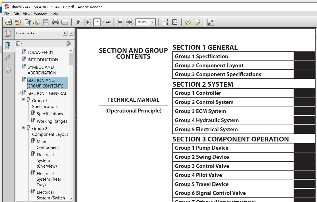
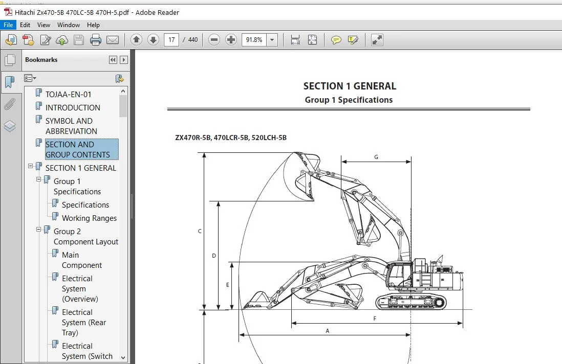
TOJAA-EN-01................................................................................................................  1
INTRODUCTION...............................................................................................................  3
SYMBOL AND ABBREVIATION....................................................................................................  5
SECTION AND GROUP CONTENTS.................................................................................................  7
SECTION 1 GENERAL..........................................................................................................  9
	Group 1 Specifications................................................................................................. 11
		Specifications..................................................................................................... 11
		Working Ranges..................................................................................................... 15
	Group 2 Component Layout............................................................................................... 19
		Main Component..................................................................................................... 19
		Electrical System (Overview)....................................................................................... 21
		Electrical System (Rear Tray)...................................................................................... 22
		Electrical System (Switch Panel)................................................................................... 23
		Electrical System (Cab Behind Side)................................................................................ 24
		Engine 1........................................................................................................... 26
		Engine 2........................................................................................................... 27
		Muffler Filter..................................................................................................... 28
		Pump Device........................................................................................................ 29
		Control Valve...................................................................................................... 30
		Check Valve........................................................................................................ 32
		Signal Control Valve............................................................................................... 32
		4-Spool Solenoid Valve Unit........................................................................................ 35
		2-Spool Solenoid Valve Unit........................................................................................ 35
		Layout of Attachment Spec. Parts (Hydraulic System)................................................................ 36
	Group 3 Component Specifications....................................................................................... 41
		Engine............................................................................................................. 41
		Engine Accessories................................................................................................. 45
		Hydraulic Component................................................................................................ 47
		Electrical Component............................................................................................... 51
SECTION 2 SYSTEM........................................................................................................... 55
	Group 1 Controller..................................................................................................... 57
		Outline............................................................................................................ 57
		CAN Circuit........................................................................................................ 58
	Group 2 Control System................................................................................................. 61
		Outline............................................................................................................ 61
		Engine Control..................................................................................................... 64
		Pump Control....................................................................................................... 92
		Valve Control......................................................................................................118
		Other Control......................................................................................................150
	Group 3 ECM System.....................................................................................................163
		Outline............................................................................................................163
		Fuel Injection Control.............................................................................................164
		Fuel Injection Amount Correction Control...........................................................................172
		EGR Control........................................................................................................174
		Preheating Control.................................................................................................176
		Alarm Control......................................................................................................177
		Muffler Filter.....................................................................................................178
		Operation..........................................................................................................179
		Muffler Filter Regenerative Control................................................................................180
		Fuel Bleeding Air Control..........................................................................................182
	Group 4 Hydraulic System...............................................................................................183
		Outline............................................................................................................183
		Pilot Circuit......................................................................................................184
		Main Circuit.......................................................................................................200
		Counterweight Removal / Installation Circuit (Optional)............................................................222
		Breaker/Pulverizer/Crusher Circuit (Optional)......................................................................224
		Oil Cooler Fan Reverse Rotation Control Circuit (Optional).........................................................232
	Group 5 Electrical System..............................................................................................233
		Outline............................................................................................................233
		Main Circuit.......................................................................................................234
		Electric Power Circuit (Key Switch: OFF)...........................................................................236
		CAN Circuit........................................................................................................238
		Accessory Circuit..................................................................................................240
		Starting Circuit (Key Switch: START)...............................................................................242
		Charging Circuit (Key Switch: ON)..................................................................................244
		Surge Voltage Prevention Circuit...................................................................................248
		Pilot Shut-Off Circuit (Key Switch: ON)............................................................................250
		Auto Shut-Down Circuit.............................................................................................252
		Engine Stop Circuit................................................................................................254
		Monitor Circuit....................................................................................................257
		Security Circuit...................................................................................................258
		Radio Circuit......................................................................................................260
		Air Conditioner Circuit............................................................................................260
		Accessory Circuit..................................................................................................263
		Work Light Circuit.................................................................................................264
		Wiper/Washer Circuit...............................................................................................268
		Cab Light Circuit..................................................................................................270
SECTION 3 COMPONENT OPERATION..............................................................................................275
	Group 1 Pump Device....................................................................................................277
		Outline............................................................................................................277
		Main Pump..........................................................................................................278
		Regulator..........................................................................................................280
		Solenoid Valve.....................................................................................................288
		Fan Pump...........................................................................................................290
		Power Control (Fan Pump)...........................................................................................292
		Flow Rate Control (Fan Pump).......................................................................................293
		Pilot Pump.........................................................................................................294
		Pump Delivery Pressure Sensor......................................................................................294
		Pump Control Pressure Sensor.......................................................................................294
	Group 2 Swing Device...................................................................................................295
		Outline............................................................................................................295
		Swing Reduction Gear...............................................................................................296
		Swing Motor........................................................................................................297
		Swing Parking Brake................................................................................................298
		Valve Unit.........................................................................................................300
	Group 3 Control Valve..................................................................................................303
		Outline............................................................................................................303
		Hydraulic Circuit..................................................................................................320
		Flow Combiner Valve................................................................................................326
		Main Relief Valve..................................................................................................328
		Overload Relief Valve (with Make-Up Function)......................................................................332
		Boom Overload Relief Valve (Low Pressure)..........................................................................338
		Regenerative Valve.................................................................................................340
		Anti-Drift Valve...................................................................................................344
		Flow Rate Control Valve............................................................................................348
		Boom Lower Meter-In Cut Valve......................................................................................356
		Bypass Shut-Out Valve..............................................................................................358
		Auxiliary Flow Combiner Valve......................................................................................360
	Group 4 Pilot Valve....................................................................................................363
		Outline............................................................................................................363
		Operation (Front Attachment / Swing and Travel Pilot Valves).......................................................365
		Operation (Auxiliary / Counterweight Removal and Installation Pilot Valve).........................................373
		Shockless Function (Only for Travel Pilot Valve)...................................................................378
	Group 5 Travel Device..................................................................................................379
		Outline............................................................................................................379
		Travel Reduction Gear..............................................................................................380
		Travel Motor.......................................................................................................382
		Parking Brake......................................................................................................384
		Travel Brake Valve.................................................................................................386
		Overload Relief Valve..............................................................................................390
		Travel Mode Control................................................................................................392
	Group 6 Signal Control Valve...........................................................................................397
		Outline............................................................................................................397
		Pilot Port.........................................................................................................398
		Shuttle Valve......................................................................................................403
		Shockless Valve....................................................................................................406
		Pump 1 Flow Rate Control Valve, Pump 2 Flow Rate Control Valve.....................................................410
		Arm Flow Rate Control Valve Control Spool, Flow Combiner Valve Control Spool, Swing Parking Brake Release Spool....412
	Group 7 Others (Upperstructure)........................................................................................413
		Pilot Shut-Off Solenoid Valve......................................................................................413
		Solenoid Valve.....................................................................................................415
		Fan Motor..........................................................................................................418
		Fan Valve..........................................................................................................419
		Pilot Relief Valve.................................................................................................422
		Shockless Valve....................................................................................................423
		Accumulator........................................................................................................424
		Distribution Valve.................................................................................................425
		Hose Rupture Valve (Optional)......................................................................................428
	Group 8 Others (Undercarriage).........................................................................................433
		Swing Bearing......................................................................................................433
		Center Joint.......................................................................................................434
		Track Adjuster.....................................................................................................435
SERVICE MANUAL REVISION REQUEST FORM.......................................................................................439
Please Note:
⦁ This is the SAME manual used by the dealers to troubleshoot any faults in your vehicle. This can be yours in 2 minutes after the payment is made.
⦁ Contact us at [email protected] should you have any queries before your purchase or that you need any other service / repair / parts operators manual.