Hitachi ZX470-5G ZX470LC-5G ZX470H-5G ZX470LCH-5G ZX470R-5G ZX470LCR-5G Hydraulic Excavator Technical Operational Principle Manual – PDF Download
Original price was: $71.95.$24.95Current price is: $24.95.
- Hitachi ZX470-5G ZX470LC-5G ZX470H-5G ZX470LCH-5G ZX470R-5G ZX470LCR-5G Hydraulic Excavator Technical Operational Principle Manual
- Part No:TOJAC-EN-00
Description
Hitachi ZX470-5G ZX470LC-5G ZX470H-5G ZX470LCH-5G ZX470R-5G ZX470LCR-5G Hydraulic Excavator Technical Operational Principle Manual
File Details:
Hitachi ZX470-5G ZX470LC-5G ZX470H-5G ZX470LCH-5G ZX470R-5G ZX470LCR-5G Hydraulic Excavator Technical Operational Principle Manual
- Manual Language:English
- Downloadable:Yes
- Pages: 380
- Size: 9.37 MB
- Format:PDF
HITACHI ZX470-5G ZX470LC-5G ZX470H-5G ZX470LCH-5G ZX470R-5G ZX470LCR-5G HYDRAULIC EXCAVATOR TECHNICAL OPERATIONAL PRINCIPLE MANUAL – PDF DOWNLOAD:
Image Preview:
Description:
Hitachi ZX470-5G ZX470LC-5G ZX470H-5G ZX470LCH-5G ZX470R-5G ZX470LCR-5G Hydraulic Excavator Technical Operational Principle Manual
To The Reader
This manual is written for an experienced technician to provide technical information needed to maintain and repair this machine.
Be sure to thoroughly read this manual for correct product information and service procedures.
If you have any questions or comments, at if you found any errors regarding the contents of this manual, please contact using “Service Manual Revision Request Form” at the end of this manual.
Additional References
Please refer to the other materials (operator’s manual, parts catalog, engine technical material and Hitachi training material etc.) in addition to this manual.
Manual Composition
This manual consists the Technical Manual, the Workshop Manual and the Engine Manual.
Information included in the Technical Manual: Technical information needed for redelivery and delivery, operation and activation of all devices and systems, operational performance tests, and troubleshooting procedures.
Information included in the Workshop Manual: Technical information needed for maintenance and repair of the machine, tools and devices needed for maintenance and repair, maintenance standards, and removal / installation and assemble / disassemble procedures.
Information included in the Engine Manual: Technical information needed for redelivery and delivery and maintenance and repair of the machine, operation and activation of all devices and systems, troubleshooting and assemble / disassemble procedures.
Table Of Content:
Hitachi ZX470-5G ZX470LC-5G ZX470H-5G ZX470LCH-5G ZX470R-5G ZX470LCR-5G Hydraulic Excavator Technical Operational Principle Manual
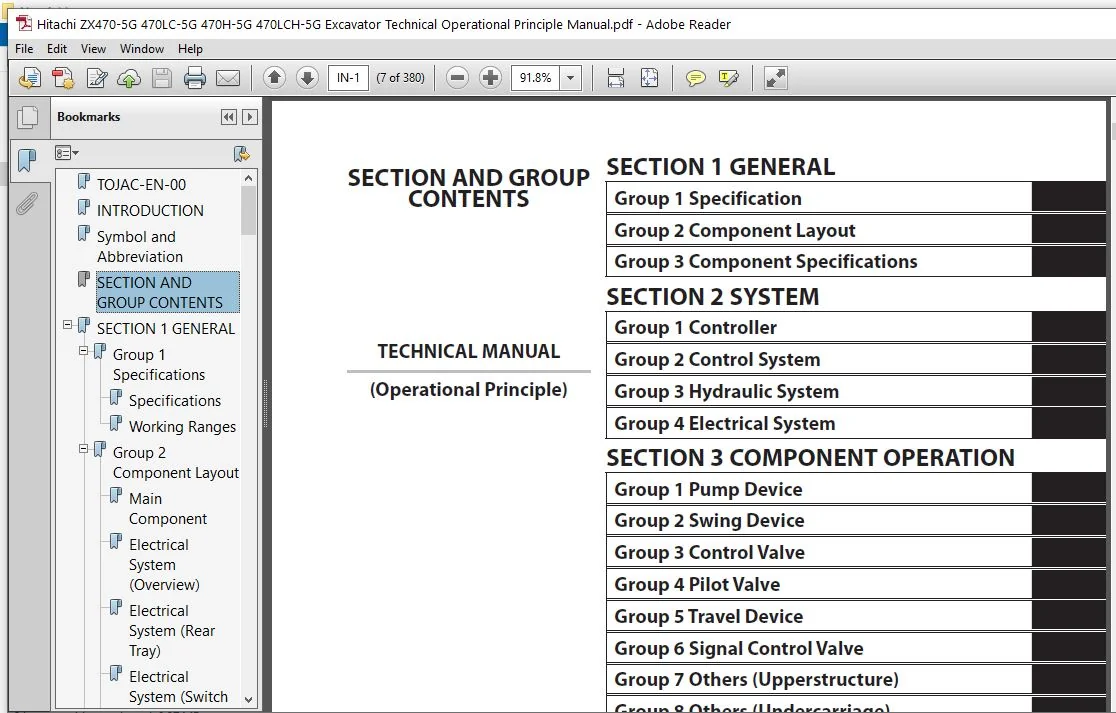
TOJAC-EN-00................................................................................................................  1
INTRODUCTION...............................................................................................................  3
Symbol and Abbreviation....................................................................................................  5
SECTION AND GROUP CONTENTS.................................................................................................  7
SECTION 1 GENERAL..........................................................................................................  9
	Group 1 Specifications................................................................................................. 11
		Specifications..................................................................................................... 11
		Working Ranges..................................................................................................... 14
	Group 2 Component Layout............................................................................................... 17
		Main Component..................................................................................................... 17
		Electrical System (Overview)....................................................................................... 19
		Electrical System (Rear Tray)...................................................................................... 20
		Electrical System (Switch Panel)................................................................................... 21
		Electrical System (Cab Behind Side)................................................................................ 22
		Isolation Switch (Optional)........................................................................................ 24
		Engine............................................................................................................. 26
		Pump Device........................................................................................................ 27
		Control Valve...................................................................................................... 28
		Check Valve / Accumulator.......................................................................................... 30
		Signal Control Valve............................................................................................... 30
		4-Spool Solenoid Valve Unit........................................................................................ 33
		2-Spool Solenoid Valve Unit........................................................................................ 33
		Layout of Attachment Spec. Parts (Hydraulic System)................................................................ 34
	Group 3 Component Specifications....................................................................................... 39
		Engine............................................................................................................. 39
		Engine Accessories................................................................................................. 43
		Hydraulic Component................................................................................................ 44
		Electrical Component............................................................................................... 48
SECTION 2 SYSTEM........................................................................................................... 51
	Group 1 Controller..................................................................................................... 53
		Outline............................................................................................................ 53
		CAN Circuit........................................................................................................ 54
	Group 2 Control System................................................................................................. 57
		Outline............................................................................................................ 57
		Engine Control..................................................................................................... 60
		Pump Control....................................................................................................... 84
		Valve Control (Standard)...........................................................................................102
		Other Control......................................................................................................128
	Group 3 Hydraulic System...............................................................................................137
		Outline............................................................................................................137
		Pilot Circuit......................................................................................................138
		Main Circuit.......................................................................................................152
		Breaker/Pulverizer/Crusher Circuit (Optional)......................................................................174
	Group 4 Electrical System..............................................................................................183
		Outline............................................................................................................183
		Main Circuit.......................................................................................................184
		Electric Power Circuit (Key Switch: OFF)...........................................................................186
		CAN Circuit........................................................................................................188
		Accessory Circuit..................................................................................................190
		Preheating Circuit (Key Switch: ON, START).........................................................................192
		Starting Circuit (Key Switch: START)...............................................................................194
		Charging Circuit (Key Switch: ON)..................................................................................198
		Surge Voltage Prevention Circuit...................................................................................202
		Pilot Shut-Off Circuit (Key switch: ON)............................................................................204
		Engine Stop Circuit................................................................................................206
		Monitor Circuit....................................................................................................209
		Security Circuit...................................................................................................210
		Radio Circuit......................................................................................................212
		Air Conditioner Circuit............................................................................................212
		Accessory Circuit..................................................................................................215
		Work Light Circuit.................................................................................................216
		Wiper/Washer Circuit...............................................................................................218
		Cab Light Circuit..................................................................................................220
SECTION 3 COMPONENT OPERATION..............................................................................................225
	Group 1 Pump Device....................................................................................................227
		Outline............................................................................................................227
		Main Pump..........................................................................................................228
		Regulators.........................................................................................................230
		Pilot Pump.........................................................................................................238
		N Sensor (Engine Speed Sensor).....................................................................................238
		Pump Delivery Pressure Sensor......................................................................................238
		Pump Displacement Angle Sensor.....................................................................................238
	Group 2 Swing Device...................................................................................................239
		Outline............................................................................................................239
		Swing Reduction Gear...............................................................................................240
		Swing Motor........................................................................................................241
		Swing Parking Brake................................................................................................242
		Valve Unit.........................................................................................................244
	Group 3 Control Valve..................................................................................................247
		Outline............................................................................................................247
		Hydraulic Circuit..................................................................................................264
		Flow Combiner Valve................................................................................................270
		Main Relief Valve..................................................................................................272
		Overload Relief Valve (with Make-Up Function)......................................................................276
		Boom Overload Relief Valve (Low Pressure)..........................................................................282
		Regenerative Valve.................................................................................................284
		Anti-Drift Valve...................................................................................................288
		Flow Rate Control Valve............................................................................................292
		Boom Lower Meter-In Cut Valve......................................................................................300
		Bypass Shut-Out Valve..............................................................................................302
		Auxiliary Flow Combiner Valve......................................................................................304
	Group 4 Pilot Valve....................................................................................................307
		Outline............................................................................................................307
		Operation (Front Attachment / Swing and Travel Pilot Valves).......................................................309
		Operation (Auxiliary / Counterweight Removaland Installation Pilot Valve)..........................................317
		Shockless Function (Only for Travel Pilot Valve)...................................................................322
	Group 5 Travel Device..................................................................................................323
		Outline............................................................................................................323
		Travel Reduction Gear..............................................................................................324
		Travel Motor.......................................................................................................326
		Parking Brake......................................................................................................328
		Travel Brake Valve.................................................................................................330
		Overload Relief Valve..............................................................................................334
		Travel Mode Control................................................................................................336
	Group 6 Signal Control Valve...........................................................................................341
		Outline............................................................................................................341
		Pilot Port.........................................................................................................342
		Shuttle Valve......................................................................................................347
		Shockless Valve....................................................................................................350
		Pump 1 Flow Rate Control Valve, Pump 2Flow Rate Control Valve......................................................354
		Arm Flow Rate Control Valve Control Spool, Flow Combiner Valve Control Spool, Swing Parking Brake Release Spool....356
	Group 7 Others (Upperstructure)........................................................................................357
		Pilot Shut-Off Solenoid Valve......................................................................................357
		Solenoid Valve.....................................................................................................359
		Fan Motor..........................................................................................................362
		Fan Valve..........................................................................................................363
		Pilot Relief Valve.................................................................................................366
		Shockless Valve....................................................................................................367
		Accumulator........................................................................................................368
		Distribution Valve.................................................................................................369
	Group 8 Others (Undercarriage).........................................................................................373
		Swing Bearing......................................................................................................373
		Center Joint.......................................................................................................374
		Track Adjuster.....................................................................................................375
SERVICE MANUAL REVISION REQUEST FORM.......................................................................................379
Please Note:
⦁ This is the same manual used by the dealers to diagnose and troubleshoot your vehicle
⦁ You will be directed to the download page as soon as the purchase is completed. The whole payment and downloading process will take anywhere between 2-5 minutes
⦁ Need any other service / repair / parts manual, please feel free to contact [email protected] . We still have 50,000 manuals unlisted