Hitachi ZX470-6 ZX470LC-6 ZX490H-6 ZX490LCH-6 ZX490R-6 ZX490LCR-6 ZX530LCH-6 Hydraulic Excavator Technical Troubleshooting Manual – PDF Download
Original price was: $69.95.$24.95Current price is: $24.95.
- Hitachi ZX470-6 ZX470LC-6 ZX490H-6 ZX490LCH-6 ZX490R-6 ZX490LCR-6 ZX530LCH-6 Hydraulic Excavator Technical Troubleshooting Manual
- Part No:TTJAG50-EN-00
Description
Hitachi ZX470-6 ZX470LC-6 ZX490H-6 ZX490LCH-6 ZX490R-6 ZX490LCR-6 ZX530LCH-6 Hydraulic Excavator Technical Troubleshooting Manual
File Details:
Hitachi ZX470-6 ZX470LC-6 ZX490H-6 ZX490LCH-6 ZX490R-6 ZX490LCR-6 ZX530LCH-6 Hydraulic Excavator Technical Troubleshooting Manual
- Manual Language:English
- Downloadable:Yes
- Pages: 1050+
- Size: 16.1 MB
- Format:PDF
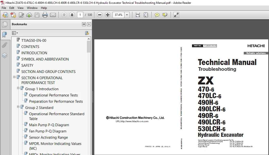
HITACHI ZX470-6 ZX470LC-6 ZX490H-6 ZX490LCH-6 ZX490R-6 ZX490LCR-6 ZX530LCH-6 HYDRAULIC EXCAVATOR TECHNICAL TROUBLESHOOTING MANUAL – PDF DOWNLOAD:
Image Preview:
Description:
Hitachi ZX470-6 ZX470LC-6 ZX490H-6 ZX490LCH-6 ZX490R-6 ZX490LCR-6 ZX530LCH-6 Hydraulic Excavator Technical Troubleshooting Manual
To The Reader
This manual is written for an experienced technician to provide technical information needed to maintain and repair this machine.The machine specification and description according to destination may be explained on this manual.
Be sure to thoroughly read this manual for correct product information and service procedures.
If you have any questions or comments, at if you found any errors regarding the contents of this manual, please contact using “Service Manual Revision Request Form” at the end of this manual.
Additional References
Please refer to the other materials (operator’s manual, parts catalog, engine technical material and Hitachi training material etc.) in addition to this manual.
Manual Composition
This manual consists the Technical Manual, the Workshop Manual and the Engine Manual.
Information included in the Technical Manual: Technical information needed for redelivery and delivery, operation and activation of all devices and systems, operational performance tests, and troubleshooting procedures.
Information included in the Workshop Manual: Technical information needed for maintenance and repair of the machine, tools and devices needed for maintenance and repair, maintenance standards, and removal / installation and assemble / disassemble procedures.
Information included in the Engine Manual: Technical information needed for redelivery and delivery and maintenance and repair of the machine, operation and activation of all devices and systems, troubleshooting and assemble / disassemble procedures.
Table Of Contents:
Hitachi ZX470-6 ZX470LC-6 ZX490H-6 ZX490LCH-6 ZX490R-6 ZX490LCR-6 ZX530LCH-6 Hydraulic Excavator Technical Troubleshooting Manual
TTJAG50-EN-00.......................................................................................................  1
CONTENTS............................................................................................................  3
INTRODUCTION........................................................................................................  7
SYMBOL AND ABBREVIATION.............................................................................................  9
SAFETY.............................................................................................................. 11
SECTION AND GROUP CONTENTS.......................................................................................... 53
SECTION 4 OPERATIONAL PERFORMANCE TEST.............................................................................. 55
	Group 1 Introduction............................................................................................ 57
		Operational Performance Tests............................................................................... 57
		Preparation for Performance Tests........................................................................... 58
	Group 2 Standard................................................................................................ 59
		Operational Performance Standard Table...................................................................... 59
		Main Pump P-Q Diagram....................................................................................... 63
		Fan Pump P-Q Diagram........................................................................................ 64
		Sensor Activating Range..................................................................................... 65
		MPDR. Monitor Indicating Values (MC)........................................................................ 66
		MPDr. Monitor Indicating Values (ECM)....................................................................... 72
	Group 3 Engine Test............................................................................................. 73
		Engine Speed................................................................................................ 73
		Lubricant Consumption....................................................................................... 76
	Group 4 Machine Performance Test................................................................................ 77
		Travel Speed................................................................................................ 77
		Track Revolution Speed...................................................................................... 78
		Mistrack Check.............................................................................................. 79
		Travel Parking Leakage...................................................................................... 80
		Swing Speed................................................................................................. 81
		Swing Function Drift Check.................................................................................. 82
		Swing Motor Leakage......................................................................................... 84
		Maximum Swingable Slant Angle............................................................................... 86
		Swing Bearing Play.......................................................................................... 88
		Hydraulic Cylinder Cycle Time............................................................................... 90
		Dig Function Drift Check.................................................................................... 92
		Control Lever Operating Force............................................................................... 95
		Control Lever Stroke........................................................................................ 96
		Combined Operation of Boom Raise and Swing Function Check................................................... 97
	Group 5 Component Test.......................................................................................... 99
		Primary Pilot Pressure...................................................................................... 99
		Secondary Pilot Pressure....................................................................................101
		4-Spool Solenoid Valve Set Pressure.........................................................................102
		2-Spool Solenoid Valve Set Pressure.........................................................................103
		Main Pump Delivery Pressure.................................................................................105
		Fan Pump Delivery Pressure..................................................................................106
		Main Relief Valve Set Pressure..............................................................................107
		Overload Relief Valve Set Pressure..........................................................................113
		Main Pump Flow Rate Measurement.............................................................................116
		Fan Pump Flow Rate Measurement..............................................................................122
		Swing Motor Drainage........................................................................................128
		Travel Motor Drainage.......................................................................................130
	Group 6 Adjustment..............................................................................................133
		Pump Learning...............................................................................................133
		Torque Adjustment...........................................................................................134
		Connection..................................................................................................135
		Rewrite of Aftertreatment Device Serial No..................................................................137
		How to Clear Fault Code.....................................................................................138
		Procedure after Replacing DCU and ECM.......................................................................139
		Air Bleeding from the Diesel Exhaust Fluid Defrosting Piping................................................140
		How to Check Manual Regeneration Switch.....................................................................141
		Remedy at DEF Pressure Decrease.............................................................................142
		Remedy at DEF Abnormal Quality..............................................................................144
		Clean DEF Tank..............................................................................................146
		Remedy When Mixing Oil DEF Tank.............................................................................147
SECTION 5 TROUBLESHOOTING...........................................................................................151
	Group 1 Diagnosing Procedure....................................................................................153
		Introduction................................................................................................153
		Diagnosis Procedure.........................................................................................154
		Electrical System Inspection................................................................................157
		Precautions for Inspection and Maintenance..................................................................158
		Instructions for Disconnecting Connectors...................................................................160
		Fuse Inspection.............................................................................................162
		Fusible Link Inspection.....................................................................................165
		Battery Voltage Check.......................................................................................166
		Alternator Check............................................................................................167
		Continuity Check............................................................................................168
		Voltage and Current Measurement.............................................................................170
		Check by False Signal.......................................................................................177
		Test Wire Harness...........................................................................................178
	Group 2 Monitor.................................................................................................181
		Outline.....................................................................................................181
		Operating Procedures of Service Menu........................................................................182
		Setting Menu................................................................................................151
		Inspection of Engine Oil Level, Coolant Level,Hour Meter, and Fuel Gauge....................................220
		Fuel Gauge, Coolant Temperature Gauge,DEF/AdBlue Gauge......................................................221
	Group 3 e-Service...............................................................................................223
		Outline.....................................................................................................223
		List of Operation Data......................................................................................224
		Communication System........................................................................................226
	Group 4 Component Layout........................................................................................227
		Main Component..............................................................................................227
		Electrical System (Overview)................................................................................229
		Electrical System (Rear Tray)...............................................................................230
		Electrical System (Switch Panel)............................................................................231
		Electrical System (Cab Behind Side).........................................................................232
		Engine 1....................................................................................................234
		Engine 2....................................................................................................235
		Aftertreatment Device.......................................................................................236
		Pump Device.................................................................................................237
		Control Valve...............................................................................................238
		DEF Tank....................................................................................................239
		Expansion Tank..............................................................................................239
		Check Valve.................................................................................................240
		Signal Control Valve........................................................................................240
		Swing Device................................................................................................242
		Travel Device...............................................................................................242
		4-Spool Solenoid Valve Unit.................................................................................243
		Fan Valve...................................................................................................243
		2-Spool Solenoid Valve Unit.................................................................................243
		Layout of Attachment Spec. Parts(Hydraulic System)..........................................................244
		Layout of Control Valve.....................................................................................248
		Pilot Port (Signal Control Valve)...........................................................................264
		Layout of Connector.........................................................................................268
		Port Layout of Control Valve (Main Circuit).................................................................278
		Port Layout of Control Valve (Pilot Circuit)................................................................280
	Group 5 Troubleshooting A.......................................................................................283
		Troubleshooting A (Base Machine DiagnosisBy Using Fault Codes) Procedure....................................283
		MC Fault Code List..........................................................................................285
		ECM Fault Code List.........................................................................................307
		DCU Fault Code List.........................................................................................321
		Monitor Controller (Monitor) Fault Code List................................................................328
		Air Conditioner Controller Fault Code List..................................................................332
		Communication Terminal Fault Code List......................................................................333
		MC Fault Codes 11000 to 11002...............................................................................335
		MC Fault Code 11003.........................................................................................336
		MC Fault Codes 11004, 11006, 11007,11009Monitor Controller (Monitor)Fault Codes 13002, 13003, 13005.........338
		CAN0 Harness Check..........................................................................................339
		ISO-CAN (Engine) Harness Check..............................................................................342
		MC Fault Codes 11005, 11008, 11010Monitor Controller (Monitor)Fault Codes 13004, 13006, 13007...............345
		CAN1 Harness Check..........................................................................................346
		MC Fault Code 11100.........................................................................................349
		MC Fault Code 11101.........................................................................................350
		MC Fault Codes 11200, 11202.................................................................................351
		MC Fault Codes 11992, 11994.................................................................................352
		MC Fault Codes 11301 to 11303...............................................................................353
		MC Fault Codes 11304, 11325.................................................................................354
		MC Fault Codes 11995, 11997, 11998..........................................................................355
		MC Fault Codes 11942 to 11944...............................................................................356
		MC Fault Codes 11945, 11978, 11979..........................................................................357
		MC Fault Code 11990.........................................................................................358
		MC Fault Code 11405.........................................................................................359
		MC Fault Code 11408.........................................................................................360
		MC Fault Code 11412.........................................................................................361
		MC Fault Code 11428.........................................................................................362
		MC Fault Code 11948.........................................................................................363
		MC Fault Code 11950.........................................................................................364
		MC Fault Code 11951.........................................................................................365
		MC Fault Code 11952.........................................................................................366
		MC Fault Code 11953.........................................................................................367
		MC Fault Code 11981.........................................................................................368
		MC Fault Code 11982.........................................................................................369
		MC Fault Code 11989.........................................................................................370
		MC Fault Code 11802.........................................................................................371
		MC Fault Code 11901.........................................................................................372
		MC Fault Codes 11910, 11911, 11914,11918, 11920.............................................................373
		MC Fault Code 11946.........................................................................................374
		MC Fault Code 11947.........................................................................................375
		MC Fault Codes 11971, 11972.................................................................................376
		MC Fault Codes 11974, 11975.................................................................................377
		MC Fault Codes 11983, 11984.................................................................................378
		MC Fault Codes 11985, 11986.................................................................................379
		MC Fault Codes 20000, 20003, 20005, 20006,20008.............................................................380
		MC Fault Codes 20009, 20010, 20062..........................................................................381
		Monitor Controller (Information)Fault Codes 13304, 13310....................................................382
		Monitor Controller (Information)Fault Code 13311............................................................383
		Monitor Controller (Information)Fault Codes 20100 to 20107, 20114...........................................384
		Monitor Controller (Information)Fault Codes 20109, 20110, 20113, 20133, 20141,20142, 20145, 20146, 20149....385
		Air Conditioner Controller Fault Codes11 to 22..............................................................386
		Air Conditioner Controller Fault Codes43 to 92..............................................................387
	Group 6 Troubleshooting B.......................................................................................389
		Troubleshooting B (Machine Diagnosis byUsing Trouble Symptom) Procedure.....................................389
		Relationship between Machine TroubleSymptoms and Related Parts..............................................391
		Correlation between Trouble Symptoms andPart Failures.......................................................419
		Engine System Troubleshooting...............................................................................437
		All Actuator System Troubleshooting.........................................................................444
		Front Attachment System Troubleshooting.....................................................................451
		Swing System Troubleshooting................................................................................464
		Travel System Troubleshooting...............................................................................467
		Other System Troubleshooting................................................................................471
		Exchange Inspection.........................................................................................478
		Emergency Boom Lowering Procedure...........................................................................481
	Group 7 Air Conditioner.........................................................................................483
		Outline.....................................................................................................483
		Functions of Main Parts.....................................................................................486
		Troubleshooting.............................................................................................491
		Air Conditioner Controller Fault Code List..................................................................492
		Air Conditioner Controller Fault Codes 11 to 22.............................................................493
		Air Conditioner Controller Fault Codes 43 to 92.............................................................494
		Work after Replacing Components.............................................................................516
		Refill Compressor Oil.......................................................................................517
		Charge Air Conditioner with Refrigerant.....................................................................518
		Hose and Pipe Tightening Torque.............................................................................526
SERVICE MANUAL REVISION REQUEST FORM................................................................................529
The Attached Diagram List...........................................................................................530
Please Note:
⦁ This is the SAME MANUAL used by the dealerships to diagnose your vehicle
⦁ No waiting for couriers / posts as this is a PDF manual and you can download it within 2 minutes time once you make the payment.
⦁ Your payment is all safe and the delivery of the manual is INSTANT – You will be taken to the DOWNLOAD PAGE.
⦁ So have no hesitations whatsoever and write to us about any queries you may have : heydownloadss @gmail.com