Hitachi ZX60LC-6 Hydraulic Excavator Workshop Manual – PDF DOWNLOAD
Original price was: $85.95.$23.95Current price is: $23.95.
Hitachi ZX60LC-6 Hydraulic Excavator Workshop Manual
Part No : WDBR50-EN-00
Description
Hitachi ZX60LC-6 Hydraulic Excavator Workshop Manual
FILE DETAILS:
Hitachi ZX60LC-6 Hydraulic Excavator Workshop Manual
Language : English
Pages : 683
Downloadable : YES
Format : PDF
Size : 27.4 MB
Part No : WDBR50-EN-00
DESCRIPTION:
Hitachi ZX60LC-6 Hydraulic Excavator Workshop Manual
INTRODUCTION:
TO THE READER:
• This manual is written for an experienced technician to provide technical information needed to maintain and repair this machine.
• Be sure to thoroughly read this manual for correct product information and service procedures.
• If you have any questions or comments, at if you found any errors regarding the contents of this manual, please contact using “Service Manual Revision Request Form” at the end of this manual.
ADDITIONAL REFERENCES:
• Please refer to the materials listed below in addition to this manual.
• The Operator’s Manual
• The Parts Catalog
• The Engine Manual
• Parts Catalog of the Engine
• Hitachi Training Material
MANUAL COMPOSITION:
• This manual consists of three portions: the Technical Manual (Operational Principle), the Technical Manual (Troubleshooting) and the Workshop Manual.
• Information included in the Technical Manual (Operational Principle): technical information needed for redelivery and delivery, operation and activation of all devices and systems.
• Information included in the Technical Manual (Troubleshooting): technical information needed for operational performance tests, and troubleshooting procedures.
• Information included in the Workshop Manual: technical information needed for maintenance and repair of the machine, tools and devices needed for maintenance and repair, maintenance standards, and removal/installation and assemble/ disassemble procedures.
TABLE OF CONTENTS:
Hitachi ZX60LC-6 Hydraulic Excavator Workshop Manual
Group 1 Precautions for Disassembling and Assembling
Precautions for Disassembling and
AssemblingW1-1-1-1
Group 2 Tightening
Tightening Bolts and NutsW1-2-1-1
Piping JointW1-2-1-4
Group 3 Painting
PaintingW1-3-1-1
Group 4 Bleeding Air
Bleeding Air from Hydraulic SystemW1-4-1-1
Bleeding Air from Fuel SystemW1-4-1-2
Air Bleeding from the Diesel Exhaust Fluid
Defrosting PipingW1-4-1-4
Group 5 Preparation
Preparation before Inspection and
MaintenanceW1-5-1-1
Hydraulic Circuit Pressure Release ProcedureW1-5-1-3
Pressure Release from Hydraulic Oil TankW1-5-1-4
Pressure Release from Expansion Tank W1-5-1-5
SECTION 1
GENERAL
CONTENTS
WDBR50-EN-00(20171222)
(Blank)
WDBR50-EN-00(20171222)
Group 1 Upperstructure
Pump DeviceW2-1-1-1
Swing MotorW2-1-2-1
Group 2 Undercarriage
Travel MotorW2-2-1-1
SprocketW2-2-1-3
Front IdlerW2-2-2-1
Upper RollerW2-2-3-1
Lower RollerW2-2-3-2
TrackW2-2-4-1
Group 3 Front Attachment
Pin and BushingW2-3-1-1
Side Cutter (2015428, 2015429)W2-3-1-3
Point (963228)W2-3-1-4
Standard Dimensions for Arm and Bucket
ConnectionW2-3-1-5
Standard Dimensions for Arm and Boom
ConnectionW2-3-1-6
CylinderW2-3-2-1
SECTION 2
MAINTENANCE STANDARD
CONTENTS
WDBR50-EN-00(20171222)
(Blank)
WDBR50-EN-00(20171222)
Group 1 Cab
Removal and Installation of CabW3-1-1-1
Dimensions of Cab GlassW3-1-2-1
Group 2 Counterweight
Removal and Installation of CounterweightW3-2-1-1
Group 3 Main Frame
Removal and Installation of Main FrameW3-3-1-1
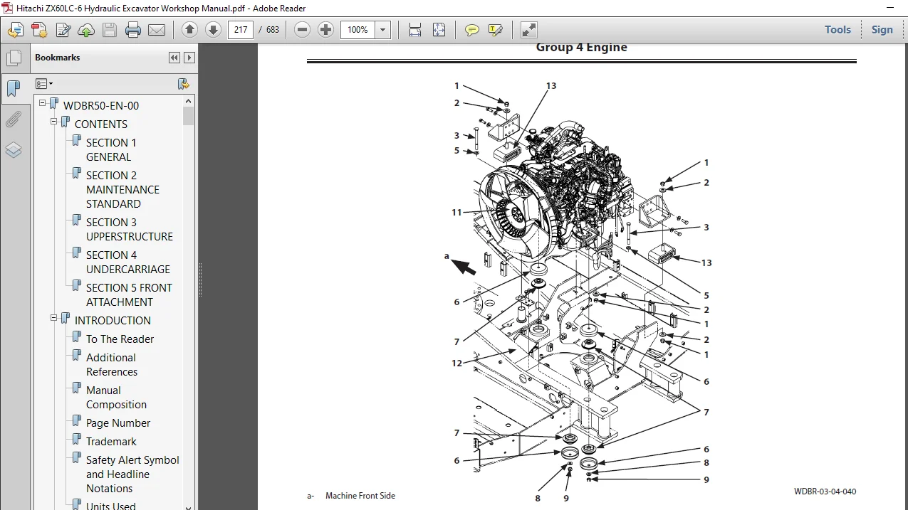
Group 4 Engine
Removal and Installation of EngineW3-4-1-1
Group 8 Pump Device
Removal and Installation of Pump DeviceW3-8-1-1
Removal and Installation of CouplingW3-8-2-1
Disassembly of Pump DeviceW3-8-3-1
Assembly of Pump DeviceW3-8-3-8
Disassembly of RegulatorW3-8-4-1
Assembly of RegulatorW3-8-4-3
Disassembly of Solenoid Valve UnitW3-8-5-1
Assembly of Solenoid Valve UnitW3-8-5-3
Structure of Pilot PumpW3-8-6-1
Group 9 Control Valve
Removal and Installation of Control ValveW3-9-1-1
Disassembly of HousingW3-9-2-1
Assembly of HousingW3-9-2-3
Disassembly of Control Valve (A Side)W3-9-3-1
Assembly of Control Valve (A Side)W3-9-3-8
Disassembly of Control Valve (B Side)W3-9-4-1
Assembly of Control Valve (B Side)W3-9-4-8
Group 10 Swing Device
Removal and Installation of Swing DeviceW3-10-1-1
Disassembly of Swing Reduction GearW3-10-2-1
Assembly of Swing Reduction GearW3-10-2-6
Disassembly of Swing MotorW3-10-3-1
Assembly of Swing MotorW3-10-3-4
Group 11 Pilot Valve
Removal and Installation of Pilot
Valve (Left)W3-11-1-1
Removal and Installation of Pilot
Valve (Right)W3-11-2-1
Removal and Installation of Travel Pilot
ValveW3-11-3-1
Disassembly of Pilot Valves (Right and Left)W3-11-4-1
Assembly of Pilot Valves (Right and Left)W3-11-4-4
Disassembly of Travel Pilot ValveW3-11-5-1
Assembly of Travel Pilot ValveW3-11-5-5
Group 12 Solenoid Valve
Removal and Installation of Pilot Shut-Off
Solenoid ValveW3-12-1-1
Removal and Installation of 3-Spool
Solenoid Valve UnitW3-12-2-1
Removal and Installation of 2-Spool
Solenoid Valve UnitW3-12-3-1
Disassembly of Pilot Shut-Off Solenoid
ValveW3-12-4-1
Assembly of Pilot Shut-Off Solenoid ValveW3-12-4-3
Structure of 3-Spool Solenoid Valve UnitW3-12-5-1
Structure of 2-Spool Solenoid Valve UnitW3-12-6-1
Group 13 Signal Control Valve
Removal and Installation of Signal
Control ValveW3-13-1-1
Structure of Signal Control ValveW3-13-2-1
Group 14 Aftertreatment Device
Removal and Installation of
Aftertreatment DeviceW3-14-1-1
Group 15 DEF Tank
Removal and Installation of DEF TankW3-15-1-1
Group 16 Coolant Control Valve
Removal and Installation of Coolant
Control ValveW3-16-1-1
Group 17 DEF Supply Module
Removal and Installation of DEF Supply
ModuleW3-17-1-1
SECTION 3
UPPERSTRUCTURE
CONTENTS
WDBR50-EN-00(20171222)
(Blank)
WDBR50-EN-00(20171222)
Group 1 Swing Bearing
Removal and Installation of Swing BearingW4-1-1-1
Disassembly of Swing BearingW4-1-2-1
Assembly of Swing BearingW4-1-2-4
Group 2 Travel Device
Removal and Installation of Travel DeviceW4-2-1-1
Disassembly of Travel DeviceW4-2-2-1
Assembly of Travel DeviceW4-2-2-5
Disassembly of Travel MotorW4-2-3-1
Assembly of Travel MotorW4-2-3-4
Disassembly of Brake ValveW4-2-4-1
Assembly of Brake ValveW4-2-4-3
Precautions for Using Floating SealW4-2-5-1
Group 3 Center Joint
Removal and Installation of Center JointW4-3-1-1
Disassembly of Center JointW4-3-2-1
Assembly of Center JointW4-3-2-3
Replacement of Body and SpindleW4-3-2-6
Group 4 Track Adjuster
Removal and Installation of Track AdjusterW4-4-1-1
Disassembly of Front IdlerW4-4-2-1
Assembly of Front IdlerW4-4-2-4
Disassembly of Track AdjusterW4-4-3-1
Assembly of Track AdjusterW4-4-3-5
Precautions for Using Floating SealW4-4-4-1
Group 6 Upper and Lower Rollers
Removal and Installation of Upper RollerW4-6-1-1
Removal and Installation of Lower RollerW4-6-2-1
Disassembly of Lower RollerW4-6-3-1
Assembly of Lower RollerW4-6-3-3
Precautions for Using Floating SealW4-6-4-1
Group 7 Track
Removal and Installation of TrackW4-7-1-1
SECTION 4
UNDERCARRIAGE
CONTENTS
WDBR50-EN-00(20171222)
(Blank)
WDBR50-EN-00(20171222)
Group 1 Front Attachment
Removal and Installation of Front
AttachmentW5-1-1-1
Group 2 Cylinder
Removal and Installation of Boom CylinderW5-2-1-1
Removal and Installation of Arm CylinderW5-2-2-1
Removal and Installation of Bucket CylinderW5-2-3-1
Removal and Installation of Positioning
CylinderW5-2-4-1
Disassembly of Boom, Arm, and Bucket
CylindersW5-2-5-1
Assembly of Boom, Arm, and Bucket
CylindersW5-2-5-8
Disassembly of Positioning CylinderW5-2-6-1
Assembly of Positioning CylinderW5-2-6-6
Group 3 Hose Rupture Valve
Removal and Installation of Hose Rupture
Valve for Boom CylinderW5-3-1-1
Removal and Installation of Hose Rupture
Valve for Arm CylinderW5-3-2-1
Removal and Installation of Hose Rupture
Valve for Positioning CylinderW5-3-3-1
Structure of Hose Rupture Valve for Boom
Cylinder (Right)W5-3-4-1
Structure of Hose Rupture Valve for Boom
Cylinder (Left)W5-3-4-3
Structure of Hose Rupture Valve for Arm
CylinderW5-3-4-5
Structure of Hose Rupture Valve for
Positioning CylinderW5-3-4-7
HITACHI ZX60LC-6 HYDRAULIC EXCAVATOR WORKSHOP MANUAL – PDF DOWNLOAD:
IMAGES PREVIEW OF THE MANUAL:
PLEASE NOTE:
- This is the SAME manual used by the dealers to troubleshoot any faults in your vehicle. This can be yours in 2 minutes after the payment is made.
- Contact us at [email protected] should you have any queries before your purchase or that you need any other service / repair / parts operators manual.